Table of Contents
Advertisement
Quick Links
Advertisement
Table of Contents

Subscribe to Our Youtube Channel
Summary of Contents for IFM E43406
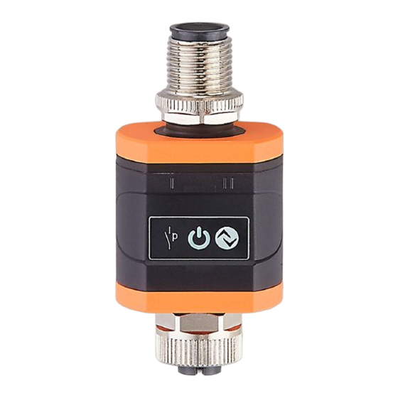
- Page 1 Operating instructions IO-Link data splitter E43406 E43410...
-
Page 2: Table Of Contents
8�1 Parameters ��������������������������������������������������������������������������������������������������13 9 Operation �����������������������������������������������������������������������������������������������������������14 9�1 Operation and diagnostics display ��������������������������������������������������������������14 9�2 Delay times ��������������������������������������������������������������������������������������������������15 10 Technical data and scale drawing ��������������������������������������������������������������������15 11 Maintenance, repair and disposal ��������������������������������������������������������������������15 1 Preliminary note Technical data, approvals, accessories and further information at www�ifm�com�... -
Page 3: 1�1 Symbols Used
1.1 Symbols used ► Instructions > Reaction, result → Cross-reference Important note Non-compliance may result in malfunction or interference� Information Supplementary note� 2 Safety instructions • The device described is a subcomponent for integration into a system� - The manufacturer is responsible for the safety of the system� - The system manufacturer undertakes to perform a risk assessment and to create a documentation in accordance with legal and normative requirements to be provided to the operator and user of the system�... -
Page 4: Functions And Features
The device is suitable for use in industrial applications� The connected sensor / actuator (→ Fig. 4.1) must have IO-Link functionality� For system integration the Y cable EVC843 is required (→ Accessories). 3.1.1 Device types Order no. Electrical design Output logic (figures) E43406 → 6.1 E43410... -
Page 5: 3�1�2 Restriction Of The Application Area
3.1.2 Restriction of the application area The device must not be integrated into an existing IO-Link connection� • The device is intended for indoor use only� • For the possible influence of the sensor signals → 9.2� 4 Function 4.1 System integration The prerequisite is a conventional sensor / actuator system without IO-Link that consists of a sensor / actuator and a respective counterpart: data splitter... - Page 6 The data splitter is installed using a Y cable between the sensor / actuator and the controller: Fig� 4�2: Example of a system integration 1: Sensor / actuator (IO-Link device) 4: data splitter E434xx 2: Controller / installation 5: IO-Link master 3: Y cable (EVC843) In the configuration of fig.
-
Page 7: 4�2 Write Protection Against Unauthorised Access
The IODDs necessary for the configuration of the data splitter and the connected IO-Link device, detailed information about process data structure, diagnostic information, parameter addresses and the necessary information about the required hardware and software can be found at www�ifm�com� 5 Installation 5.1 Installation location / installation environment ►... -
Page 8: 5�2 Installation Procedure
► Mount the device so that it is accessible� In case of concealed installation, mark the installation location in an appropriate way to ensure it can be found� The maximum distance between the individual IO-Link components is 20 m� Maximum distance between (3) and (2), fig. 4.2: → Technical data of the connection cables used and of the other connected components�... -
Page 9: Electrical Connection
3: L- (from the master) 4: C: IO-Link 1: L+ (from the installation) 2: C/Q: IO-Link 3: L- (from the installation) to the Y cable (2) 4: switching output OUT1 / IO-Link PNP (E43406) or NPN (E43410) 5: not connected... - Page 10 1: L+ (from the installation) 2: switching output / analogue output OUT2, if available to the 3: L- (from the installation) installation (4) 4: switching output OUT1 / IO-Link PNP (E43406) or NPN (E43410) 5: not connected During parameter setting (→ 8)
-
Page 11: 6�1 Electrical Design Of The Output Stage
► Observe the electrical design of the type used: Type Electrical design Output logic (general) E43406 E43410 Pin 2 and pin 5 of the IO-Link device (connection (3) (→ 6)) are connected through to the installation side (4) in the Y cable EVC843. So for IO-Link devices with a signal on pin 2 (e�g�... -
Page 12: Parameter Setting
8 Parameter setting To set the device parameters an IODD (IO Device Description) is needed. More information: (→ 4.3) For many applications the data splitter is ready for operation on delivery (plug & play). For connected IO-Link devices that support the automatic output configuration (e�g�... -
Page 13: 8�1 Parameters
8.1 Parameters Name Description OutputConfiguration Selection between the automatic output configuration auto (default) and the manual output configuration. Restore factory Default command to restore factory settings� settings WriteProtect Write protection for the connected IO-Link device� If write protection is active (parameter to 'on') write access of the master is rejected by the data splitter�... -
Page 14: Operation
9 Operation ► Check whether the unit operates correctly� 9.1 Operation and diagnostics display Description LED 1 LED 2 LED 3 Supply voltage too low Device fault flashes at 1 Hz Normal operation IO-Link master connected No IO-Link master connected or flashes at 1 Hz IO-Link master not detected No IO-Link device connected or... -
Page 15: 9�2 Delay Times
(depends on the device, → Technical data of the connected IO-Link components). So the total response time is approx� 102�3 ms� 10 Technical data and scale drawing Technical data and scale drawing at www�ifm�com� 11 Maintenance, repair and disposal ► It is not possible to repair the unit�...


Need help?
Do you have a question about the E43406 and is the answer not in the manual?
Questions and answers