Stryker S3 MedSurg 3002 Maintenance Manual
Bed
Hide thumbs
Also See for S3 MedSurg 3002:
- Operation manual (78 pages) ,
- Operation manual (58 pages) ,
- Operation manual (72 pages)

Related Manuals for Stryker S3 MedSurg 3002


Summary of Contents for Stryker S3 MedSurg 3002
- Page 1 ® MedSurg Bed 3002 International 230V Maintenance Manual 2017/03 C.0 3006-409-006 REV C www.stryker.com...
-
Page 3: Table Of Contents
Introduction ................Intended Use – Stryker S3 ®... - Page 4 Lift Header Assembly with Load Cells ............3006-409-006 REV C www.stryker.com...
- Page 5 Optional Litter Assembly, HWI with 1 Stryker Port ....... . .
- Page 6 International Warranty Clause............3006-409-006 REV C www.stryker.com...
-
Page 7: Symbols
Refer to your local distributor for return and/or collection systems available in your country. Non-ionizing radiation; i.e. RF transmitter (WiFi) Return To Table of Contents www.stryker.com 3006-409-006 REV C... -
Page 8: Warning/Caution/Note Definition
Note This provides special information to make maintenance easier or important instructions clearer. Return To Table of Contents 3006-409-006 REV C www.stryker.com... -
Page 9: Introduction
This manual is designed to assist you with the maintenance of the S3 ® MedSurg Bed, Model 3002. Read it thoroughly before using the equipment. INTENDED USE – STRYKER S3 ® The S3 ® MedSurg Bed, Model 3002 is intended to support and transport patients within the Med/Surg and Critical Care hospital environments. -
Page 10: Specifications
>= 35” >= 88,9 cm Length >= 84” >= 213,4 cm 80 lbs 36.3 kg The above stated mattress specifications assist in ensuring the product conforms to HBSW and IEC specifications. Return To Table of Contents 3006-409-006 REV C www.stryker.com... -
Page 11: Environmental Conditions
1060 hPa Atmospheric Pressure 700 hPa 500 hPa Stryker reserves the right to change specifications without notice. Specifications listed are approximate and may vary slightly from unit to unit or by power supply fluctuations. Return To Table of Contents www.stryker.com... -
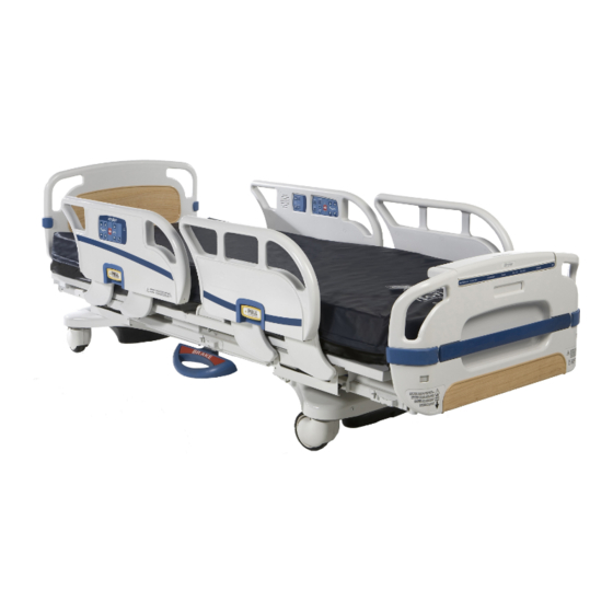
Page 12: Product Illustration
Introduction PRODUCT ILLUSTRATION Patient Headboard Control Panel Siderail Nurse Footboard Control Panel Control Panel Steer Pedal (not shown) Siderail Release Handle Brake Pedal Footboard Caster Return To Table of Contents 3006-409-006 REV C www.stryker.com... -
Page 13: Contact Information
Stryker Medical 3800 E. Centre Avenue Portage, Michigan 49002 Please have the serial number (A) of your Stryker product available when calling Stryker Customer Service or Technical Support. Include the serial number in all written communication. SERIAL NUMBER LOCATION The serial number is located at the head end of the bed just below the headboard and above the power cord where it comes out from the frame. -
Page 14: Safety Tips And Guidelines
Use only a Stryker supplied interface cable. Use of any other cable may cause the bed to function improperly, which may result in patient or user injury. - Page 15 The safe working load of the defibrillator tray is 40 lbs. • The safe working load of the oxygen holder is 45 lbs. • Scale accuracy specifications do not apply for patients under 50 lbs. Return To Table of Contents www.stryker.com 3006-409-006 REV C...
-
Page 16: Ibed® Awareness Option
Awareness as the display information to troubleshoot the bed will get lost. • If the optional iBed® Awareness system is being used, use of accessories that cover the center and side alert lights at the footboard are not recommended. Return To Table of Contents 3006-409-006 REV C www.stryker.com... -
Page 17: Static Discharge Precautions
2 and 3 of the following procedure. Do not place unprotected circuit boards on the floor. All circuit boards to be returned to Stryker Medical should be shipped in the static shielding bags the new boards were shipped in. Static Protection Procedure Unplug the power cord from the wall receptacle. -
Page 18: Setup Procedures
• Use only a Stryker supplied interface cable. Use of any other cable may cause the bed to function improperly which may result in patient or user injury. •... -
Page 19: Maintenance Menu Guide
HR, FL or FR will be displayed below the message. (Refer to the Error Handling Section). • If no errors are present, then the maintenance menu will be displayed and menu items 1-9 above may be accessed where applicable. Return To Table of Contents www.stryker.com 3006-409-006 REV C... - Page 20 If an error occurs during the procedure the display will show an error message, “Calibration Error,” for four seconds. WARNING Ensure there is no patient on the bed while the calibration procedure is being performed. Return To Table of Contents 3006-409-006 REV C www.stryker.com...
- Page 21 Down Scroll Display Selected Scroll Display Selected Is ‘New’ Setting Item Up One item. Item Down One item. Display = “Save Successful” (Hold message for 2 seconds) Return to Maintenance Menu Return To Table of Contents www.stryker.com 3006-409-006 REV C...
- Page 22 To Clear the Information: In the Maintenance Menu, select the Clear Scale Stats item; then press and hold the Enter/Check button. The following message will be shown on the display screen: “Clear Scale Statistics?” Return To Table of Contents 3006-409-006 REV C www.stryker.com...
- Page 23 In the Maintenance Menu, select the Scale Units item; then press and hold the Enter/Check button. The Scale Units Screen will display Figure 41 with the current state as the highlighted item. Return To Table of Contents www.stryker.com 3006-409-006 REV C...
- Page 24 Exit Menu • This feature allows the operator to exit the menu back to the previous screen. • When this menu item is selected the screen will exit to the “Status” screen. Return To Table of Contents 3006-409-006 REV C www.stryker.com...
-
Page 25: Preventive Maintenance
_____ Check Nurse Call battery - optional equipment _____ Check labels, as specified in the Operations and Maintenance manuals to ensure legibility, proper adherence and integrity. Bed Serial Number: Completed by: _______________________________________ Date: ___________________ Return To Table of Contents www.stryker.com 3006-409-006 REV C... -
Page 26: Grease Points
Apply Mobile #28 grease to the entire length of the ball screw. If dry, apply a thin film layer of Syn-Tech grease (p/n 3000-200-700) to the outside of the brake spring. Ball Screw Brake Spring Return To Table of Contents 3006-409-006 REV C www.stryker.com... -
Page 27: Cleaning
Some cleaning products are corrosive in nature and may cause damage to the product if used improperly. If the products described above are used to clean Stryker patient care equipment, measures must be taken to ensure the beds are wiped with a damp cloth soaked in clean water and thoroughly dried following cleaning. Failure to properly rinse and dry the beds will leave a corrosive residue on the surface of the bed, possibly causing premature corrosion of critical components. -
Page 28: Troubleshooting Guide
If the CPU board has been replaced, reconfigure the bed by resetting the: Bed Type, Bed Options, Serial Number, Burn-in Limits (Fowler and Height) and calibrating the scale. G. Verify bed function and return to service. Return To Table of Contents 3006-409-006 REV C www.stryker.com... - Page 29 Verify the motors are running, if so, replace lift couplers. If motors are not running, check voltage at motor connection. If voltage is present at motor, check capacitors or motors. D. Verify bed function and return to service. Return To Table of Contents www.stryker.com 3006-409-006 REV C...
- Page 30 3 (white), of the CPU board while pressing gatch down. If voltage is not present, replace the CPU board. If 5VDC is present, check the capacitor and motor. C. Verify bed function and return to service. Return To Table of Contents 3006-409-006 REV C www.stryker.com...
-
Page 31: Ibed® Awareness System Error Codes
Scale System HL-Load Cell Patient Head Left Load Cell. Under/Over Logged Scale, Bed Exit, range. iBed® Awareness HR-Load Cell Patient Head Right Load Cell. Under/Over Logged Scale, Bed Exit, range. iBed® Awareness Return To Table of Contents www.stryker.com 3006-409-006 REV C... -
Page 32: Error Messages
The message “Scale Calib. Err” will be displayed in the lower status screen window. Return To Table of Contents 3006-409-006 REV C www.stryker.com... - Page 33 This will cause the product to stop all function and product a message screen indicating the error number and the message “Unknown Bed Type - Call Service” Return To Table of Contents www.stryker.com 3006-409-006 REV C...
- Page 34 CalibrationException If the scale calibration routine fails then the Message Motion message “Calibration Error” will be displayed for 4 seconds and then return to the mainte- nance menu. Return To Table of Contents 3006-409-006 REV C www.stryker.com...
-
Page 35: Quick Reference Replacement Parts List
The parts and accessories listed on this page are all currently available for purchase. Some of the parts identified on the assembly drawing parts in this manual may not be individually available for purchase. Please call Stryker Customer Service USA: 1-800-327-0770 for availability and pricing. - Page 36 Potentiometer, Foot End 3001-200-230 Potentiometer, Head End 3006-200-240 Power Cord (Argentina) 0039-006-000 Power Cord (British) 0059-772-000 Power Cord (European) 0059-168-000 Single Tube of Grease 3000-200-700 Head/Footboard “C” Bumper Adhesive 0072-002-071 Fowler Potentiometer 3001-345-807 Return To Table of Contents 3006-409-006 REV C www.stryker.com...
-
Page 37: Service Information
Push the brake rod through the frame until the brake pedal is clear. Remove the brake pedal. Reverse the above steps to attach the new brake pedal. Note Use Loctite 242 when reinstalling the bolts and torque the bolts to 25 foot-pounds. Return To Table of Contents www.stryker.com 3006-409-006 REV C... -
Page 38: Lift Motor And Capacitor Removal And Replacement
The drive shaft on the new motor probably will have to be turned to be aligned with the coupler. Use a 7/16” open end wrench to turn the drive shaft of the motor. The procedure for lift motor and capacitor removal and replacement is the same for both ends of the bed. Return To Table of Contents 3006-409-006 REV C www.stryker.com... -
Page 39: Lift Housing Removal And Replacement
Using a 7/32” hex Allen socket, remove the two screws (A) holding the lift screws to the header crossbar plate. CAUTION The bed litter retracts on rollers. Secure it to prevent it from rolling while the procedure is being done. Return To Table of Contents www.stryker.com 3006-409-006 REV C... - Page 40 12. Reverse the above steps to reinstall the lift housing assembly after service is completed. Note The procedure for lift housing removal and replacement is the same for both ends of the bed. Return To Table of Contents 3006-409-006 REV C www.stryker.com...
-
Page 41: Lift Potentiometer Replacement And Adjustment
10. Reverse steps 4-8 to install the new potentiometer and potentiometer housing assembly. 11. After installing the new potentiometer, the “burn-in” procedure below must be followed. Note Be sure to maintain the potentiometer position while installing. Return To Table of Contents www.stryker.com 3006-409-006 REV C... -
Page 42: Lift Potentiometer "Burn-In" Procedure
16” - 16 3/8” with the litter fully down and 29 1/4” - 29 7/8” with the litter fully up. WARNING Ensure there is no patient on the bed while the burn-in procedure is being performed. Return To Table of Contents 3006-409-006 REV C www.stryker.com... -
Page 43: Lift Motor Isolation Plate Replacement
Use a 7/16” open end wrench to turn the drive shaft of the motor. WARNING Ensure there is no patient on the bed while the procedure is being performed. Return To Table of Contents www.stryker.com 3006-409-006 REV C... -
Page 44: Lift Motor Coupler Replacement
The motor coupler can now be removed from the lift housing. Reverse the above steps to install the new motor coupler and bushings. WARNING Ensure there is no patient on the bed while the replacement procedure is being performed. Return To Table of Contents 3006-409-006 REV C www.stryker.com... -
Page 45: Power And Sensor Coil Cord Replacement
Arrange the cords exactly as shown in the illustration (left in front of right). If this is not done correctly, damage to the cords will result. WARNING Ensure there is no patient on the bed while the replacement procedure is being performed. Return To Table of Contents www.stryker.com 3006-409-006 REV C... -
Page 46: Power And Sensor Coil Cord Replacement Illustration
Service Information POWER AND SENSOR COIL CORD REPLACEMENT ILLUSTRATION VIEW FROM CENTER OF BED View from Center of Bed Return To Table of Contents 3006-409-006 REV C www.stryker.com... -
Page 47: Knee Motor Removal And Replacement
Gatch section. Reinstall the pin, the wires for the auto contour switch, and the motion interrupt pan. 13. Test the bed for proper operation before returning it to service. WARNING Ensure there is no patient on the bed while the replacement procedure is being performed. Return To Table of Contents www.stryker.com 3006-409-006 REV C... -
Page 48: Fowler Motor Cam And Cam Guide Replacement
Reverse the above steps to install the replacement cam and cam guide/micro switch assembly. Refer to page WARNING Ensure there is no patient on the bed while the replacement procedure is being performed. Return To Table of Contents 3006-409-006 REV C www.stryker.com... -
Page 49: Limit Setting - Fowler Motor
Ensure the head section will lower to flat (0) before returning the bed to service. Verify the head section lowers onto the rubber rests and the motor stops running. Reinstall the litter access panels removed in step 1. Return To Table of Contents www.stryker.com 3006-409-006 REV C... -
Page 50: Fowler Motor Removal And Replacement
(p/n 3000-200-700) to the brake spring. Reverse the above steps to install the new motor assembly and reattach all litter panels. Test the bed for proper operation before returning it to service. Return To Table of Contents 3006-409-006 REV C www.stryker.com... -
Page 51: Fowler Motor Drive Isolator And Cpr Decoupler Removal And Replacement
Put the springs in the isolator and install it on the shaft. Reinstall the fowler motor (page 50). Run the Fowler up and down several times to test it before returning the bed to service. Return To Table of Contents www.stryker.com 3006-409-006 REV C... -
Page 52: Fowler Motor Ball Screw Assembly Replacement
10. To prevent the ball nut from coming off the drive screw, cable tie both ends of the ball screw. 11. Pull the ball screw toward the foot of the bed and remove the head end of the ball screw assembly from the support. Return To Table of Contents 3006-409-006 REV C www.stryker.com... -
Page 53: Head Motor Brake/Clutch Replacement
Using the snap ring pliers, install the new snap ring. Using the wire cutters, remove the four wire ties from the new brake/clutch. Reinstall the fowler motor (page 50). Test the bed for proper operation before returning it to service. Return To Table of Contents www.stryker.com 3006-409-006 REV C... -
Page 54: Load Cell Replacement
CAUTION Be sure the load cell’s strain gauge is facing up when installing a new load cell or the weigh system will not work properly. Recalibrate the weigh system (page 20). Return To Table of Contents 3006-409-006 REV C www.stryker.com... -
Page 55: Load Cell Replacement - Grease Points
LOAD CELL REPLACEMENT - GREASE POINTS Apply Syn-Tech NS-18191-G grease (p/n 3000-200-700) to rollers on the Lift Header Assembly as shown in figure below. Rollers Rollers Litter Assembly (Reference p/n: 3006-375-197) Return To Table of Contents www.stryker.com 3006-409-006 REV C... -
Page 56: Power Supply Replacement
Lift Potentiometer “Burn-In” procedures on page c. If your Bed is equipped with a Scale System, execute the Scale Calibration procedures on page 10. Test bed operations before returning the bed to service. Return To Table of Contents 3006-409-006 REV C www.stryker.com... -
Page 57: Soft Config. Procedures
S3.) Hit “Enter” on the footboard panel to confirm the bed type; hit “Exit” to cancel the operation. = Accept X = Cancel Figure S-3 Return To Table of Contents www.stryker.com 3006-409-006 REV C... - Page 58 OFF, Zoom or Battery Backup. Scroll up or down to select one of the three available items and hit Zoom “Enter” on the footboard panel. Batt. = Save X = Cancel Figure S-6 Return To Table of Contents 3006-409-006 REV C www.stryker.com...
- Page 59 Figure S-9 will be displayed. You can set the Scale option to ON or OFF. Hit “Enter” on the footboard panel to make your selection or hit “Exit” to cancel. = Save X = Cancel Figure S-9 Return To Table of Contents www.stryker.com 3006-409-006 REV C...
- Page 60 Bed Exit Option to OFF, Multi Zone or Single Zone. Hit “Enter” on the footboard panel to make your selection or “Exit” to cancel. Mu lt i Zone Single Zone = Save X = Cancel Figure S-12 Return To Table of Contents 3006-409-006 REV C www.stryker.com...
- Page 61 Awareness will then automatically be set to OFF as well. It cannot be set to ON unless either kind of Bed Exit was previously chosen. = Save X = Cancel Figure S-15 Return To Table of Contents www.stryker.com 3006-409-006 REV C...
- Page 62 Note that the user can see the state of the items Bed Type [S3] previously set. Bed Options [SET] S e ri a l Nu m b e r Clear All Figure S-18 Return To Table of Contents 3006-409-006 REV C www.stryker.com...
- Page 63 Figure S-20 Edit SN 21. If the Edit SN item is selected, the screen in Figure S-21 will be displayed to the user. 080115000 = Save X = Cancel Figure S-21 Return To Table of Contents www.stryker.com 3006-409-006 REV C...
- Page 64 Current SN item, the screen in Figure S-26 will be displayed. The entered serial number will be displayed until the user hits the “Exit” button on the footboard panel. 080115000 Figure S-26 Return To Table of Contents 3006-409-006 REV C www.stryker.com...
- Page 65 Bed Motion Lock. The screen will display the message “Hold to Set Height Limits.” Once the lock button is held for two seconds, the message “Release Button” will Figure S-29 flash. Return To Table of Contents www.stryker.com 3006-409-006 REV C...
- Page 66 I.E., the user must choose the Bed Type, set all options to either ON, OFF or some variety of the option, enter the serial number and burn-in the height limits in order to exit the Bed Config. menu on a power cycle. Return To Table of Contents 3006-409-006 REV C www.stryker.com...
- Page 67 Bed Ty p e the Bed Type menu item as shown in Figure S-35 and the user can now re-enter all the bed information starting with the Bed Type. Figure S-35 Return To Table of Contents www.stryker.com 3006-409-006 REV C...
-
Page 68: Optional Smart Tv Interface "Burn-In" Procedure
TV Config. 2 Zenith 1 TV Config. 3 Zenith 2 TV Config. 4 Philips TV Config. 5 Magnavox TV Config. 6 Traditional Traditional Traditional Plus Traditional Plus Auto-Configure Auto-Config. Auto-Configure DV Auto-Config. DV Return To Table of Contents 3006-409-006 REV C www.stryker.com... -
Page 69: Fowler Potentiometer Replacement
“Burn-In” menu. The menu item should now read “Fowler Limits [SET]”. Unplug the bed and plug back in to return to normal operating mode. WARNING Ensure there is no patient on the bed while the burn-in procedure is being performed. Return To Table of Contents www.stryker.com 3006-409-006 REV C... -
Page 70: Head And Foot Siderail Cover Removal
Remove the cables from the siderail. Make note of the proper location for the cables. Reverse the above steps to reattach the cover. CAUTION Do not snag the cables when installing the siderail cover. Return To Table of Contents 3006-409-006 REV C www.stryker.com... -
Page 71: Head Siderail Hoop Replacement
11. Lift the head siderail hoop straight up and out. 12. Remove the inner siderail boards and reinstall on the new head siderail hoop. 13. Reverse steps 2-11 to install a new siderail hoop. Return To Table of Contents www.stryker.com 3006-409-006 REV C... -
Page 72: Footboard Module Removal
Lift the module out and replace. Reverse the above steps to attach the replacement door and/or hinge. Note Screw (B) is a machine screw and must be reinstalled in the proper hole. Return To Table of Contents 3006-409-006 REV C www.stryker.com... -
Page 73: Footboard Interface Plug Replacement
Be sure to install the plug with the flat edge (B) at the top left, as shown in the illustration, or the footboard interface plug will not mate properly with the bed. Damage to the plug or the footboard could result. Return To Table of Contents www.stryker.com 3006-409-006 REV C... -
Page 74: Bed Circuit Boards
Bed Circuit Boards CPU BOARD - 3006-308-900 Return To Table of Contents 3006-409-006 REV C www.stryker.com... -
Page 75: Cpu Board - 3006-308-900 (Continued)
Head Lift Up 230VAC w/Switch 0VAC w/o Switch Pin 3 Black Pin 1 Red Foot Lift Down 230VAC w/Switch 0VAC w/o Switch Pin 6 White Pin 1 Red Foot Lift Up 230VAC w/Switch Return To Table of Contents www.stryker.com 3006-409-006 REV C... -
Page 76: Software Configuration
Locate switch bank 4, labeled SB4 on the CPU board (see above). Move switch one to the “ON” position (see below). To verify the switch settings, check what the footboard LCD displays. General Setting, S3 Bed Return To Table of Contents 3006-409-006 REV C www.stryker.com... -
Page 77: Power Supply - 0059-157-000
Pin 2 Pin 4 or 5 Pin 3 Pin 4 or 5 Pin 4 Pin 4 or 5 Pin 5 Pin 4 or 5 -12V Pin 6 Pin 4 or 5 Return To Table of Contents www.stryker.com 3006-409-006 REV C... -
Page 78: Ibed Enhanced Nurse Call Option, 37-Pin Plugover Board - 3006-303-900
(Select N.O. N.C. or OFF ) N.O. N.C. (Check Here) (Check Here) (Check Here) Low Height Alert (SB2): SW7, SW8 (Select N.O. N.C. or OFF ) N.O. N.O. (Check Here) (Check Here) (Check Here) Return To Table of Contents 3006-409-006 REV C www.stryker.com... - Page 79 (Check Here) Not Used (SB1): SW7, SW8 ( Do Not Select ) I Bed Alert (SB2): SW1, SW2 (Select N.O. N.C. or N.C. N.O. OFF ) (Check Here) (Check Here) (Check Here) Return To Table of Contents www.stryker.com 3006-409-006 REV C...
-
Page 80: Head Wall Output Configuration
Head Wall Output Configuration Stryker Pendant Port 37-Pin Connector Pin 1 iBed® Awareness Status On Pin 2 Read Light Pin 3 Room Light Pin 4 Speaker High Pin 5 Potentiometer Wiper Pin 6 Bed Exit Status On Pin 7 Nurse Call Interlock... -
Page 81: Bed Assembly, Standard Bed
Bed Assembly, Standard Bed For Reference Only: 3006-075-102 Return To Table of Contents www.stryker.com 3006-409-006 REV C... - Page 82 Bed Assembly, Standard Bed Return To Table of Contents 3006-409-006 REV C www.stryker.com...
- Page 83 Bed Assembly, Standard Bed Return To Table of Contents www.stryker.com 3006-409-006 REV C...
- Page 84 Bed Assembly, Standard Bed Return To Table of Contents 3006-409-006 REV C www.stryker.com...
- Page 85 Bed Assembly, Standard Bed Return To Table of Contents www.stryker.com 3006-409-006 REV C...
- Page 86 FE Siderail Assembly, Left 3006-400-400 FE Siderail Assembly, Right 3006-300-033 Mattress Retainer 0025-120-000 Rivet 3006-300-275 Shield, Right 3006-300-276 Shield, Left 0011-180-000 Flat Washer 0016-028-000 Fiberlock Hex Nut 0059-126-000 Push-Mount Wire Clip Return To Table of Contents 3006-409-006 REV C www.stryker.com...
-
Page 87: Bed Assembly, Ibed® Awareness Option
Bed Assembly, iBed® Awareness Option (Scale, Bed Exit, Zone Control) For Reference Only: 3006-500-115 Return To Table of Contents www.stryker.com 3006-409-006 REV C... - Page 88 Foot End Siderail Assembly, LH 3006-400-405 Foot End Siderail Assembly, RH 3006-500-100 Footboard Assembly 3002-317-003 Scale/Bed Exit Option Assembly 3006-326-501 Load Cell Bed Lift Header Assembly 1 3006-307-501 Load Cell Bed Lift Header Assembly 1 Return To Table of Contents 3006-409-006 REV C www.stryker.com...
-
Page 89: Base Assembly, Standard Bed
Base Assembly, Standard Bed For Reference Only: 3006-275-003 Return To Table of Contents www.stryker.com 3006-409-006 REV C... - Page 90 Base Assembly, Standard Bed Torque item R to 20 ± 5 ft-lb Torque item R to 20 ± 5 ft-lb Return To Table of Contents 3006-409-006 REV C www.stryker.com...
- Page 91 Base Assembly, Standard Bed Return To Table of Contents www.stryker.com 3006-409-006 REV C...
- Page 92 Base Assembly, Standard Bed Return To Table of Contents 3006-409-006 REV C www.stryker.com...
- Page 93 Base Assembly, Standard Bed Return To Table of Contents www.stryker.com 3006-409-006 REV C...
- Page 94 Base Assembly, Standard Bed Typical Both Ends Return To Table of Contents 3006-409-006 REV C www.stryker.com...
- Page 95 Base Assembly, Standard Bed Return To Table of Contents www.stryker.com 3006-409-006 REV C...
- Page 96 Brake Cam Shaft Bushing 3001-200-334 Spring 3001-200-342 Steer Lock Cable 3006-200-381 Steer Swivel Lever 3006-201-371 Steer Pedal Arm Assembly 3002-200-302 Brake Ratchet Link Assembly 3002-200-305 Brake Ratchet Crank, Left 3002-200-306 Brake Ratchet Crank, Right Return To Table of Contents 3006-409-006 REV C www.stryker.com...
- Page 97 Caster Cover, LH 3006-200-139 Caster Cover, RH 3002-200-311 Brake Shaft 3002-200-313 Brake Cam Spacer 3006-200-312 Brake Cam 3006-200-374 Swivel Lever 3006-200-376 Swivel Lock Activation Spring 3006-200-379 Swivel Lock Return Spring, LH 0011-611-001 Washer Return To Table of Contents www.stryker.com 3006-409-006 REV C...
-
Page 98: Lift Assembly (Head And Foot End)
Head End Pot Assembly 3001-200-230 Foot End Pot Assembly 3006-275-275 Lift Common Components Ass’y, HE 3001-200-815 Lift Sensor Coil Cord, FE 3006-200-815 Lift Sensor Coil Cord, HE 3006-275-275 Lift Common Components Ass’y, FE Return To Table of Contents 3006-409-006 REV C www.stryker.com... -
Page 99: Lift Assembly
Lift Assembly For Reference Only: 3006-275-275 Return To Table of Contents www.stryker.com 3006-409-006 REV C... - Page 100 Lift Assembly Return To Table of Contents 3006-409-006 REV C www.stryker.com...
- Page 101 Lift Assembly 0004-245-000 (Holds Bellow Brackets) Torque item G to 15-25 in-lb Return To Table of Contents www.stryker.com 3006-409-006 REV C...
- Page 102 3000-300-455 Isolation Bushing 3001-200-214 Isolation Plate Assembly 3001-200-228 Mounting Standoff 3001-200-864 Cable Power Coil 3001-300-019 Isolation Sleeve 3002-200-052 Bellows Bracket 3002-200-235 Idler Manual Override Shaft 3221-016-603 Lift Motor 0026-231-000 Dowel Pin Return To Table of Contents 3006-409-006 REV C www.stryker.com...
-
Page 103: Motor Isolation Plate Assembly
Motor Isolation Plate Assembly For Reference Only: 3001-200-214 Item Part No. Part Name Qty. 3001-200-213 Isolation Plate 3000-300-442 Grommet Return To Table of Contents www.stryker.com 3006-409-006 REV C... -
Page 104: Brake Shaft Assembly, Standard Bed
Brake Shaft Assembly, Standard Bed For Reference Only: 3006-200-340 Item Part No. Part Name Qty. 0004-270-000 Socket Head Cap Screw 3006-200-314 Brake Shaft 3006-200-325 Brake Pedal Return To Table of Contents 3006-409-006 REV C www.stryker.com... -
Page 105: Brake Crank Assembly
Brake Crank Assembly For Reference Only: 3006-200-330 Item Part No. Part Name Qty. 0014-004-000 Washer 0025-146-000 Rivet 3001-200-311 Brake Link 3001-200-312 Dog Leg Brake Link 3002-200-309 Brake Crank 3006-200-302 Brake Shaft Crank Return To Table of Contents www.stryker.com 3006-409-006 REV C... -
Page 106: Brake Bar Assembly
Part No. Part Name Qty. 0005-018-000 Carriage Bolt 0016-035-000 Nylock Hex Nut 3000-200-318 Guide Pin 3002-200-310 Brake Bar Return Spring 3000-200-324 Brake Bar Bumper 3003-200-323 Brake Bar 3006-200-327 Toothed Brake Ring Return To Table of Contents 3006-409-006 REV C www.stryker.com... -
Page 107: Swivel Lock Caster Assembly - 3006-200-060
Swivel Lock Caster Assembly - 3006-200-060 Item Part No. Part Name Qty. 0003-342-000 Hex Head Cap Screw 0016-060-000 Lock Nut 3006-200-059 Caster Horn with Bearing and Swivel 1 3006-200-142 Molded Wheel Assembly, White Return To Table of Contents www.stryker.com 3006-409-006 REV C... -
Page 108: Steer Swivel Caster Assembly - 3006-200-065
Steer Swivel Caster Assembly - 3006-200-065 Item Part No. Part Name Qty. 0003-342-000 Hex Head Cap Screw 0016-060-000 Lock Nut 3006-200-063 Caster Horn with Bearing and Steer Swivel, White 3006-200-142 Molded Wheel Assembly Return To Table of Contents 3006-409-006 REV C www.stryker.com... -
Page 109: 6" Molded Wheel Assembly - 3006-200-142
6” Molded Wheel Assembly - 3006-200-142 Item Part No. Part Name Qty. 0081-226-000 Bearing 0715-001-255 Wheel Bushing 3006-200-141 Molded Wheel, White 6060-002-046 Bearing Spacer Return To Table of Contents www.stryker.com 3006-409-006 REV C... -
Page 110: Bottom Cover - 3001-200-022
Bottom Cover - 3001-200-022 Item Part No. Part Name Qty. 3002-001-100 Bottom Cover 3000-000-039 Grommet Return To Table of Contents 3006-409-006 REV C www.stryker.com... -
Page 111: Litter Assembly, Standard Components
Litter Assembly, Standard Components For Reference Only: 3006-300-002 Return To Table of Contents www.stryker.com 3006-409-006 REV C... - Page 112 Litter Assembly, Standard Components Return To Table of Contents 3006-409-006 REV C www.stryker.com...
- Page 113 Litter Assembly, Standard Components Return To Table of Contents www.stryker.com 3006-409-006 REV C...
- Page 114 Litter Assembly, Standard Components Return To Table of Contents 3006-409-006 REV C www.stryker.com...
- Page 115 3006-088-820 Caution Label 3001-300-008 Bumper 3006-301-097 CPU Cover Assembly 3001-300-099 Fowler Modified Bushing 3006-301-170 Thigh Litter Assembly 3002-300-870 8” Litter Ground Jumper 3006-301-135 Seat Weldment Skin 3006-090-100 500 Lb. Maximum Label Return To Table of Contents www.stryker.com 3006-409-006 REV C...
-
Page 116: Litter Assembly, Standard Bed
Litter Assembly, Standard Bed For Reference Only: 3006-375-002 Return To Table of Contents 3006-409-006 REV C www.stryker.com... - Page 117 Litter Assembly, Standard Bed Return To Table of Contents www.stryker.com 3006-409-006 REV C...
- Page 118 Litter Assembly, Standard Bed Return To Table of Contents 3006-409-006 REV C www.stryker.com...
- Page 119 Litter Assembly, Standard Bed Return To Table of Contents www.stryker.com 3006-409-006 REV C...
- Page 120 Litter Assembly, Standard Bed Return To Table of Contents 3006-409-006 REV C www.stryker.com...
- Page 121 Litter Assembly, Standard Bed Return To Table of Contents www.stryker.com 3006-409-006 REV C...
- Page 122 Foot Litter Weldment 3006-300-349 3001-345-807 Fowler Pot Cable 3004-345-450 Pot Linkage Assembly 3001-400-558 Spacer 0007-065-000 Truss Head Screw 3000-300-113 8” Cable Tie 3001-345-809 Fowler Pot Extension Cable 0013-002-001 External Serrated Tooth Lock Washer Return To Table of Contents 3006-409-006 REV C www.stryker.com...
-
Page 123: Foot Prop Assembly, Standard Length Bed - 3003-034-010
Foot Prop Assembly, Standard Length Bed - 3003-034-010 Item Part No. Part Name Qty. 0027-007-000 Cotter Pin 0052-754-000 Nyliner Bushing 0058-056-000 Black Edge Trim 3” 3003-300-162 Foot Prop Rod Return To Table of Contents www.stryker.com 3006-409-006 REV C... -
Page 124: Litter Cpu Cover Assembly - 3006-301-097
Label, Shock Hazard 3001-300-663 Velcro® Strip 7900-001-291 Foam Tape (12.25”) 7900-001-291 Foam Tape (5.75”) 7900-001-291 Foam Tape (11.75”) 7900-001-291 Foam Tape (4.25”) 7900-001-291 Foam Tape (21.38”) 3006-300-098 CPU Cover 3006-508-105 Label, WiFi Capable Return To Table of Contents 3006-409-006 REV C www.stryker.com... -
Page 125: Foot Cover Assembly - 3003-300-042
Foot Cover Assembly - 3003-300-042 Item Part No. Part Name Qty. 0988-002-708 Caution Label 7900-001-291 Foam Tape 1.5’ 3003-300-043 Foot Cover Return To Table of Contents www.stryker.com 3006-409-006 REV C... -
Page 126: Electrical Litter Assembly, Standard Bed
Electrical Litter Assembly, Standard Bed For Reference Only: 3006-375-895 Assemble connector to frame in the orientation shown. Return To Table of Contents 3006-409-006 REV C www.stryker.com... - Page 127 Electrical Litter Assembly, Standard Bed Return To Table of Contents www.stryker.com 3006-409-006 REV C...
- Page 128 Electrical Litter Assembly, Standard Bed Return To Table of Contents 3006-409-006 REV C www.stryker.com...
- Page 129 Electrical Litter Assembly, Standard Bed Return To Table of Contents www.stryker.com 3006-409-006 REV C...
- Page 130 Electrical Litter Assembly, Standard Bed Return To Table of Contents 3006-409-006 REV C www.stryker.com...
- Page 131 Switch Plunger 3001-300-877 Siderail Extension Cable 3001-300-865 Motion Interrupt Lift Sensor Cable 0030-048-000 Strain Relief 0030-047-000 Strain Relief 3000-300-113 Cable Tie 0011-077-000 Washer 3002-300-874 Litter Ground Jumper 0013-038-000 Washer 0016-033-000 Kep Nut Return To Table of Contents www.stryker.com 3006-409-006 REV C...
- Page 132 CPU to Siderail Sensor Cable 0059-400-000 8 AMP Circuit Breaker 3006-275-003 Base Assembly 3006-375-625 230V Specification Label 3221-300-897 230V Gatch Power Cable 3221-300-271 230V Snubber Cable Assembly 2030-009-901 WEEE Label 5212-100-807 Caution Label Return To Table of Contents 3006-409-006 REV C www.stryker.com...
-
Page 133: Mechanical Litter Assembly
Mechanical Litter Assembly For Reference Only: 3006-375-197 Return To Table of Contents www.stryker.com 3006-409-006 REV C... - Page 134 Mechanical Litter Assembly Return To Table of Contents 3006-409-006 REV C www.stryker.com...
- Page 135 Mechanical Litter Assembly Return To Table of Contents www.stryker.com 3006-409-006 REV C...
- Page 136 Mechanical Litter Assembly Return To Table of Contents 3006-409-006 REV C www.stryker.com...
- Page 137 3006-375-550 Fowler Drive Assembly 3006-300-206 Moving Frame Assembly 3006-300-303 Stationary Frame Assembly 7900-001-291 1” Vibration Tape 3002-300-870 8” Litter Ground Jumper 3006-301-422 Motor Shield 0011-159-000 Steel Washer 3005-300-004 Carriage Bolt Spacer Return To Table of Contents www.stryker.com 3006-409-006 REV C...
-
Page 138: Moving Frame Assembly
Moving Frame Assembly For Reference Only: 3006-300-206 Moving Frame Assembly - 3006-300-206 (Reference Only) Item Part No. Part Name Qty. 0005-049-000 Flat Head Square Neck Bolt Assy 3006-300-205 Moving Frame Weldment Return To Table of Contents 3006-409-006 REV C www.stryker.com... -
Page 139: Cpr Damper Assembly Option
Item Part No. Part Name Qty. 0003-221-000 Hex Washer Head Screw 0011-448-000 Plain Washer 0052-818-000 Powdered Metal Flange Bearing 3001-200-229 Mounting Standoff 3006-345-488 CPR Damper 3006-345-490 Bracket - Damper Mount Assembly Return To Table of Contents www.stryker.com 3006-409-006 REV C... -
Page 140: Lift Header Assembly - No Load Cells
Hex Soc. Hd. Cap Screw 0011-004-000 Flat Washer 0013-032-000 Ext. Tooth Lock Washer 0016-010-000 Hex Flanged Nylock Nut 3006-301-530 Lift Header Assembly 3002-300-353 Roller Cap 3002-300-871 Ground Jumper 3001-300-511 Imitation Load Cell Return To Table of Contents 3006-409-006 REV C www.stryker.com... -
Page 141: Lift Header Assembly With Load Cells
3002-300-353 Roller Cap 3002-300-871 Ground Jumper 3002-300-871 Ground Jumper 3002-307-057 Load Cell - 750 lbs 3002-307-057 Load Cell - 750 lbs 3006-326-010 Iso. Foley Bag, LH 3006-326-020 Iso. Foley Bag, RH Return To Table of Contents www.stryker.com 3006-409-006 REV C... -
Page 142: Gatch Motor Assembly - 3006-375-420
Gatch Motor Mounting Plate 3001-300-225 Motor Mount Bracket 0052-817-000 Grommet 3002-300-421 Gatch Limit Bracket 3000-300-041 Micro Switch 0002-107-000 Phillips Round Head Screw 0016-069-000 Twin-Type Fastener 3221-016-602 Gatch Motor 3000-300-114 Wire Tie (not shown) Return To Table of Contents 3006-409-006 REV C www.stryker.com... -
Page 143: Fowler Drive Assembly
Fowler Drive Assembly For Reference Only: 3006-375-550 Return To Table of Contents www.stryker.com 3006-409-006 REV C... - Page 144 3006-375-705 Fowler Actuator Assembly 0014-083-000 Flat Washer 3000-300-457 CPR Ball Screw 3006-301-496 Fowler Link 3002-300-493 Fowler Link Bracket 0025-092-000 Rivet 3006-300-121 Motor Mount Isolator 3006-300-122 Isolator Plate 3006-300-123 Mounting Plate Tabs Return To Table of Contents 3006-409-006 REV C www.stryker.com...
-
Page 145: Fowler Actuator Assembly - 3006-375-705
Thrust Needle Roller Bearing 3000-200-224 Idler Gear Thrust Washer 3001-300-569 Brake Cup 3001-300-552 CPR Brake Disc 3001-300-551 CPR Spring Cup 3001-300-563 CPR Brake Spring 3001-300-570 CPR Spring Cup 4712-116-004 Fowler Motor 230V Return To Table of Contents www.stryker.com 3006-409-006 REV C... -
Page 146: Fowler Brake Kit Assembly - 3001-300-775
3001-300-551 CPR Spring Cup 3001-300-563 CPR Brake Spring 3001-300-570 CPR Spring Cup 0003-064-000 Hex Head Cap Screw 3001-300-776 Flat Washer 0011-193-000 Heavy Flat Washer 0016-035-000 Nylock Nut 3000-300-113 8” Wire Tie Return To Table of Contents 3006-409-006 REV C www.stryker.com... -
Page 147: Fowler Limit Switch Assembly - 3002-343-035
Part No. Part Name Qty. 0002-003-000 Round Head Screw 0016-069-000 Twin Type Fastener 0016-129-000 Hex Washer Head Screw 3000-300-036 Fowler Cam Card 3000-300-041 Micro Switch 3000-300-044 Cam Guide 3002-300-038 Link Wire Return To Table of Contents www.stryker.com 3006-409-006 REV C... -
Page 148: Night Light Assembly - 3006-410-020
LH bottom side of moving frame (3006-300-206) RH bottom side of moving frame (3006-300-206) (No toggle switch required on RH side of bed.) Orient switch so that the “O” is towards the head end of the bed. Return To Table of Contents 3006-409-006 REV C www.stryker.com... - Page 149 0003-224-000 Hex Washer Head Screw 0059-191-000 Toggle Switch 3000-300-113 8” Cable Tie 3002-310-018 Night Light Cover 3002-310-010 LED Lens 3002-310-025 Retaining Spacer 3006-310-601 Night Light Label 3002-036-801 Night Light Wiring Harness Return To Table of Contents www.stryker.com 3006-409-006 REV C...
-
Page 150: Optional Scale/Bed Exit Assembly
Optional Scale/Bed Exit Assembly For Reference Only: 3002-317-003 Return To Table of Contents 3006-409-006 REV C www.stryker.com... - Page 151 Optional Scale/Bed Exit Assembly - 3002-317-003 (Reference Only) Item Part No. Part Name Qty. 3002-317-835 FE Load Cell Cable 3002-317-834 HE Load Cell Cable 0007-053-000 Truss Head Screw 3000-300-113 8” Cable Tie Return To Table of Contents www.stryker.com 3006-409-006 REV C...
-
Page 152: Optional Litter Assembly, Communication Capability
Optional Litter Assembly, Communication Capability For Reference Only: 3006-303-122 Return To Table of Contents 3006-409-006 REV C www.stryker.com... - Page 153 Optional Litter Assembly, Communication Capability - 3006-303-122 (Reference Only) Item Part No. Part Name Qty. 0012-046-000 Split Lock Washer 0037-220-000 Hole Plug 0059-710-000 Caplug 3000-300-113 8” Cable Tie 3001-300-007 Screwjack 3001-303-821 Headwall Interface Cable Return To Table of Contents www.stryker.com 3006-409-006 REV C...
-
Page 154: Optional Litter Assembly, Nurse Call And Communication
Optional Litter Assembly, Nurse Call and Communication For Reference Only: 3006-303-052 Return To Table of Contents 3006-409-006 REV C www.stryker.com... -
Page 155: Optional Litter Assembly, Nurse Call And Communication
Item Part No. Part Name Qty. 0012-046-000 Lock Washer 0059-710-000 Caplug 3000-300-113 8” Cable Tie 3001-300-007 Screwjack 3001-303-821 Headwall Interface Cable 3006-303-045 Battery Enclosure Assembly 0044-029-000 1” Tape 0037-220-000 Hole Plug Return To Table of Contents www.stryker.com 3006-409-006 REV C... -
Page 156: Optional Litter Assembly, Hwi With 1 Stryker Port
Optional Litter Assembly, HWI with 1 Stryker Port For Reference Only: 3006-314-012 Return To Table of Contents 3006-409-006 REV C www.stryker.com... - Page 157 Optional Litter Assembly, HWI with 1 Stryker Port Optional Litter Assembly, HWI with 1 Stryker Port - 3006-314-012 (Reference Only) Item Part No. Part Name Qty. 0003-224-000 Hex Washer Head Screw 0007-053-000 Truss Head Screw 0012-046-000 Lock Washer 0059-710-000 Static Plug...
-
Page 158: Optional Litter Assembly, Nurse Call And 1/4" Port
Optional Litter Assembly, Nurse Call and 1/4” Port For Reference Only: 3006-314-013 Return To Table of Contents 3006-409-006 REV C www.stryker.com... - Page 159 Lock Washer 0044-029-000 1” Tape 0059-710-000 Caplug 3000-300-113 8” Cable Tie 3001-300-007 Screwjack 3001-303-821 Headwall Interface Cable 3006-303-045 Battery Enclosure Assembly 3006-316-006 Pendant Port Cover, White 3006-383-100 1/4” Headwall Interface Port Ass’y Return To Table of Contents www.stryker.com 3006-409-006 REV C...
-
Page 160: Optional Ibed Enhanced Nurse Call, 37-Pin Plugover Assembly
Optional iBed Enhanced Nurse Call, 37-Pin Plugover Assembly (Applies to beds with iBed® Awareness option only) For Reference Only: 3006-303-010 3006-308-900 Return To Table of Contents 3006-409-006 REV C www.stryker.com... - Page 161 Optional iBed Enhanced Nurse Call, 37-Pin Plugover Board - 3006-303-010 (Reference Only) Item Part No. Part Name Qty. 3006-303-900 37-Pin Plugover Assembly Board 3006-303-800 iBed® Awareness Plugover Board Cable 3001-300-007 Jackscrew 3000-300-113 8” Cable Tie 0059-144-000 Split Ferrite Return To Table of Contents www.stryker.com 3006-409-006 REV C...
-
Page 162: Battery Enclosure Assembly
Battery Enclosure Assembly For Reference Only: 3006-303-045 Item Part No. Part Name Qty. 0029-008-000 Dual Lock 0029-010-000 Dual Lock 3000-303-871 Battery - 9V 3001-303-811 Battery Cable 3006-304-012 Battery Enclosure 7900-001-291 1.75” Foam Tape Return To Table of Contents 3006-409-006 REV C www.stryker.com... -
Page 163: Head End Siderail Assembly
Head End Siderail Assembly For Reference Only: 3006-400-105 (LH) 3006-400-205 (RH) (LEFT SIDERAIL SHOWN) Return To Table of Contents www.stryker.com 3006-409-006 REV C... - Page 164 Head End Siderail Assembly Return To Table of Contents 3006-409-006 REV C www.stryker.com...
- Page 165 Head End Siderail Assembly Return To Table of Contents www.stryker.com 3006-409-006 REV C...
- Page 166 Head End Siderail Assembly Return To Table of Contents 3006-409-006 REV C www.stryker.com...
- Page 167 Head End Siderail Assembly Return To Table of Contents www.stryker.com 3006-409-006 REV C...
- Page 168 Head End Siderail Assembly Return To Table of Contents 3006-409-006 REV C www.stryker.com...
- Page 169 Head End Siderail Assembly LEFT SIDERAIL (3006-400-105) RIGHT SIDERAIL (3006-400-205) Return To Table of Contents www.stryker.com 3006-409-006 REV C...
- Page 170 Head Left/Foot Right 3006-400-537 Latch Disk, Head Left/Foot Right 3006-400-544 Glide Rod, Head End AW 3006-400-540 Gas Spring Mounting Bracket 1 3006-400-549 Latch Return Spring 3006-400-551 Spring Plunger BB 3006-400-552 Spring Arm, A Return To Table of Contents 3006-409-006 REV C www.stryker.com...
- Page 171 Head Right/Foot Left 3006-400-541 Latch Disk, Head Right/Foot Left 3006-400-544 Glide Rod, Head End AW 3006-400-540 Gas Spring Mounting Bracket 1 3006-400-549 Latch Return Spring 3006-400-551 Spring Plunger BB 3006-400-552 Spring Arm, A Return To Table of Contents www.stryker.com 3006-409-006 REV C...
-
Page 172: Head End Siderail Assembly With Optional Cardiac Chair
Label Inner, Right, CC (not shown) 3001-400-522 Filler Cap 3001-400-517 Speaker Seal 3006-430-133 Label, Smart TV Blank 3006-400-637 Label Outer, Left, CC 3006-400-647 Label Outer, Right, CC (not shown) 0023-112-000 Pan Head Tapping Screw Return To Table of Contents 3006-409-006 REV C www.stryker.com... -
Page 173: Head End Siderail Assembly With Optional
Label Inner, Right, Standard (not shown) 3001-400-522 Filler Cap 3001-400-517 Speaker Seal 3006-430-133 Label, Smart TV Blank 3006-400-634 Label Outer, Left, G/F, CC 3006-400-644 Label Outer, Right, G/F, CC (not shown) 0023-112-000 Pan Head Tapping Screw Return To Table of Contents www.stryker.com 3006-409-006 REV C... -
Page 174: Head End Siderail Assembly With Optional
Filler Cap 3006-403-831 Speaker with Cable 3006-430-133 Label, Smart TV Blank 3006-400-633 Label Outer, Left, N/C, G/F, CC 3006-400-643 Label Outer, Right, N/C, G/F, CC (not shown) 0023-112-000 Pan Head Tapping Screw Return To Table of Contents 3006-409-006 REV C www.stryker.com... -
Page 175: Head End Siderail Assembly With Optional
Filler Cap 3006-403-831 Speaker with Cable 3006-430-133 Label, Smart TV Blank 3006-400-633 Label Outer, Left, N/C, G/F, CC 3006-400-643 Label Outer, Right, N/C, G/F, CC (not shown) 0023-112-000 Pan Head Tapping Screw Return To Table of Contents www.stryker.com 3006-409-006 REV C... -
Page 176: Head End Siderail Assembly With Optional
3001-400-522 Filler Cap 3006-403-831 Speaker with Cable 3006-430-133 Label, Smart TV Blank 3006-400-635 Label Outer, Left, N/C, CC 3006-400-645 Label Outer, Right, N/C, CC (not shown) 0023-112-000 Pan Head Tapping Screw Return To Table of Contents 3006-409-006 REV C www.stryker.com... -
Page 177: Head End Siderail Assembly With Optional
Filler Cap 3006-403-831 Speaker with Cable 3006-430-133 Label, Smart TV Blank 3006-400-633 Label Outer, Left, N/C, G/F, CC 3006-400-643 Label Outer, Right, N/C, G/F, CC (not shown) 0023-112-000 Pan Head Tapping Screw Return To Table of Contents www.stryker.com 3006-409-006 REV C... -
Page 178: Head End Siderail Assembly With Optional
Head End Siderail Assembly with Optional Nurse Call, Lights, Cardiac Chair and Smart TV For Reference Only: 3006-999-403 Inner Left Shown Outer Left Shown Return To Table of Contents 3006-409-006 REV C www.stryker.com... -
Page 179: Head End Siderail Assembly With Optional
Siderail Lumbar Board, Right (not shown) 3006-400-635 Label Outer, Left, NC, CC 3006-400-645 Label Outer, Right, NC, CC (not shown) 3006-402-803 PCB Siderail Cable 0023-112-000 Pan Head Tapping Screw 3003-039-800 Smart TV Auto Detect PCB Assembly Return To Table of Contents www.stryker.com 3006-409-006 REV C... -
Page 180: Head End Siderail Assembly With Optional
Head End Siderail Assembly with Optional NC, Lights, Gatch/Fowler, Cardiac Chair and Smart TV Inner Left Shown For Reference Only: 3006-999-405 Outer Left Shown Return To Table of Contents 3006-409-006 REV C www.stryker.com... - Page 181 Label Outer, Left, NC, G/F, DMS 3006-400-643 Label Outer, Right, NC, G/F, DMS (not shown) 3006-402-803 PCB Siderail Cable 0023-112-000 Pan Head Tapping Screw 3003-039-800 Smart TV Auto Detect PCB Assembly Return To Table of Contents www.stryker.com 3006-409-006 REV C...
-
Page 182: Head End Siderail Assembly, Outer Panel
Pan Head High/Low Tapping Screw 8 3001-400-953 Switch Cap 3006-400-127 Head End Siderail Cover, Left 3006-400-227 Head End Siderail Cover, Right 3006-400-920 Outer Siderail PCB Assembly, Left 3001-400-910 Outer Siderail PCB Assembly, Right 1 Return To Table of Contents 3006-409-006 REV C www.stryker.com... -
Page 183: Head End Siderail Assembly, Inner Panel
PANEL SHOWN Item Part No. Part Name Qty. 0023-112-000 Pan Head High/Low Tapping Screw 8 3001-400-953 Switch Cap 3006-400-115 Head End Toprail, Left 3006-400-215 Head End Toprail, Right 3006-400-930 Main Siderail PCB Return To Table of Contents www.stryker.com 3006-409-006 REV C... - Page 184 Release Handle Assembly For Reference Only: 3006-400-570 Item Part No. Part Name Qty. 3006-400-565 Release Handle 3006-400-657 Siderail Release Label Return To Table of Contents 3006-409-006 REV C www.stryker.com...
-
Page 185: Siderail Ass'y, Ibed® Awareness Option, He, Left - 3006-400-100
Siderail Ass’y, iBed® Awareness Option, HE, Left - 3006-400-100 REF: 3006-400-105 Siderail Standard Components Item Part No. Part Name Qty. 0003-392-000 Hex Head Machine Screw 0058-105-000 P-Clamp 3006-400-120 Siderail Switch Assembly, Head Left 1 3006-400-577 Switch Holder Spacer Return To Table of Contents www.stryker.com 3006-409-006 REV C... -
Page 186: Siderail Ass'y, Ibed® Awareness Option, He, Right - 3006-400-200
Siderail Ass’y, iBed® Awareness Option, HE, Right - 3006-400-200 REF: 3006-400-205 Siderail Standard Components Item Part No. Part Name Qty. 0003-392-000 Hex Head Machine Screw 0058-105-000 P-Clamp 3006-400-220 Siderail Switch Assembly, Head Right 1 3006-400-577 Switch Holder Spacer Return To Table of Contents 3006-409-006 REV C www.stryker.com... -
Page 187: Switch Assembly, Ibed® Awareness Option, Head End
High-Low Tapping Screw 3006-400-558 Switch Holder, Head Left, Foot Right 1 3006-400-559 Switch Holder, Head Right, Foot Left 1 3006-400-802 Head End Siderail Switch Cable Cable Tie 3006-400-806 Siderail Switch Ground Cable Return To Table of Contents www.stryker.com 3006-409-006 REV C... -
Page 188: Foot End Siderail Assembly
Foot End Siderail Assembly For Reference Only: 3006-400-300 (LH) 3006-400-400 (RH) (LEFT SIDERAIL SHOWN) Return To Table of Contents 3006-409-006 REV C www.stryker.com... - Page 189 Foot End Siderail Assembly Return To Table of Contents www.stryker.com 3006-409-006 REV C...
- Page 190 Foot End Siderail Assembly Return To Table of Contents 3006-409-006 REV C www.stryker.com...
- Page 191 Foot End Siderail Assembly Return To Table of Contents www.stryker.com 3006-409-006 REV C...
- Page 192 Foot End Siderail Assembly Return To Table of Contents 3006-409-006 REV C www.stryker.com...
- Page 193 Foot End Siderail Assembly Return To Table of Contents www.stryker.com 3006-409-006 REV C...
- Page 194 Spring Plunger Clip 3006-400-564 Glide Rod, Foot End 3006-400-570 Release Handle Assembly BB 3006-400-566 Handle Retainer Plate BC 3006-400-567 Extension Spring BD 3006-400-568 Bearing 3006-400-569 Glide Rod Restraint 3006-400-581 Machined Support Plate Return To Table of Contents 3006-409-006 REV C www.stryker.com...
- Page 195 Gas Spring AW 3006-400-561 Spring Plunger Clip 3006-400-564 Glide Rod, Foot End 3006-400-570 Release Handle Assembly BB 3006-400-566 Handle Retainer Plate BC 3006-400-567 Extension Spring BD 3006-400-568 Bearing 3006-400-569 Glide Rod Restraint Return To Table of Contents www.stryker.com 3006-409-006 REV C...
-
Page 196: Siderail Ass'y, Ibed® Awareness Option, Fe Left - 3006-400-305
Siderail Ass’y, iBed® Awareness Option, FE Left - 3006-400-305 REF: 3006-400-300 Siderail Standard Components Item Part No. Part Name Qty. 0003-392-000 Hex Head Machine Screw 0058-105-000 P-Clamp 3006-400-315 Siderail Switch Assembly, Foot Left 3006-400-577 Switch Holder Spacer Return To Table of Contents 3006-409-006 REV C www.stryker.com... -
Page 197: Siderail Ass'y, Ibed® Awareness Option, Fe, Right - 3006-400-405
Siderail Ass’y, iBed® Awareness Option, FE, Right - 3006-400-405 REF: 3006-400-400 Siderail Standard Components Item Part No. Part Name Qty. 0003-392-000 Hex Head Machine Screw 0058-105-000 P-Clamp 3006-400-415 Siderail Switch Assembly, Foot Right 1 3006-400-577 Switch Holder Spacer Return To Table of Contents www.stryker.com 3006-409-006 REV C... -
Page 198: Switch Assembly, Ibed® Awareness Option, Foot End
High-Low Tapping Screw 3006-400-558 Switch Holder, Foot Right, Head Left 1 3006-400-559 Switch Holder, Foot Left, Head Right 1 3006-400-801 Head End Siderail Switch Cable Cable Tie 3006-400-806 Siderail Switch Ground Cable Return To Table of Contents 3006-409-006 REV C www.stryker.com... -
Page 199: Optional Pendant Assembly
Optional Pendant Assembly Combination Pendant Motion/ Combination Pendant Communication Communication - 3001-315-012 Only - 3001-315-016 Combination Pendant Motion/ Combination Pendant Motion Only - 3001-315-014 Nurse Call - 3001-315-018 Return To Table of Contents www.stryker.com 3006-409-006 REV C... - Page 200 Notes Return To Table of Contents 3006-409-006 REV C www.stryker.com...
-
Page 201: Footboard Assembly, Standard
Footboard Assembly, Standard For Reference Only: 3005-500-100 Return To Table of Contents www.stryker.com 3006-409-006 REV C... - Page 202 Footboard Connector Assembly 3006-500-050 Guide Tube - Rectangular Assembly 1 3006-500-055 Guide Tube - Square Assembly 3006-500-112 Footboard Cover 3006-501-011 Footboard Module Assembly 3006-508-010 Oxygen Warning Label 3006-508-011 Footboard Screw Cover Label Return To Table of Contents 3006-409-006 REV C www.stryker.com...
-
Page 203: Footboard Pump Rack Assembly
Footboard Pump Rack Assembly For Reference Only: 3006-500-010 Item Part No. Part Name Qty. 0004-459-000 Button Head Cap Screw 3006-500-013 Footboard 3006-500-023 Footboard Pump Holder Return To Table of Contents www.stryker.com 3006-409-006 REV C... -
Page 204: Footboard Module Assembly
Bushing, Right 3006-500-029 PCB Shaft Damper Weldment 3006-500-031 PCB Mount Support 3006-500-032 Bushing, Left 3006-500-202 Footboard PCB Support 3006-501-900 Wireless Footboard PCB Assembly 3006-508-013 Label, Hospital Staff Use 3006-508-014 Label, Logo Return To Table of Contents 3006-409-006 REV C www.stryker.com... -
Page 205: Footboard Assembly, No Options
Footboard Assembly, No Options For Reference Only: 3006-500-104 Return To Table of Contents www.stryker.com 3006-409-006 REV C... - Page 206 Non-LBS Lens, Blank Inserts, RH 3006-500-082 Non-LBS Lens, Blank Inserts, LH 3006-508-004 Footboard Label, No Scale, No Bed Exit 3006-508-105 Label, WiFi Capable * Kit, Footboard Assembly, No Options - 3006-700-131 Return To Table of Contents 3006-409-006 REV C www.stryker.com...
-
Page 207: Footboard Assembly, Bed Exit Option
Footboard Assembly, Bed Exit Option For Reference Only: 3006-500-105 Return To Table of Contents www.stryker.com 3006-409-006 REV C... - Page 208 Non-LBS Lens Blank Insert, LH 3006-508-005 Footboard Label, Bed Exit 3001-400-953 Switch Cap 3006-508-109 Label, Bed Exit 3006-508-105 Label, WiFi Capable * Kit, Footboard Assembly, Single Zone Bed Exit - 3006-700-132 Return To Table of Contents 3006-409-006 REV C www.stryker.com...
-
Page 209: Footboard Assembly, Bed Exit/Scale Option
Footboard Assembly, Bed Exit/Scale Option For Reference Only: 3006-500-107 Return To Table of Contents www.stryker.com 3006-409-006 REV C... - Page 210 Non-LBS Lens Blank Insert, LH 3006-508-007 Footboard Label, Bed Exit, Scale 3001-400-953 Switch Cap 3006-508-109 Label, Bed Exit 3006-508-107 Label, Scale 3006-508-105 Label, WiFi Capable * Kit, Footboard Assembly, Single Zone Bed Exit/Scale - 3006-700-133 Return To Table of Contents 3006-409-006 REV C www.stryker.com...
-
Page 211: Footboard Assembly, Bed Exit/Zone Control Option
Footboard Assembly, Bed Exit/Zone Control Option For Reference Only: 3006-500-106 Return To Table of Contents www.stryker.com 3006-409-006 REV C... - Page 212 3006-508-006 Footboard Label, Bed Exit with Zone Control 3001-400-953 Switch Cap 3006-508-106 Label, Bed Exit with Zone Control 3006-508-105 Label, WiFi Capable * Kit, Footboard Assembly, Multi-Zone Bed Exit - 3006-700-134 Return To Table of Contents 3006-409-006 REV C www.stryker.com...
-
Page 213: Footboard Assembly, Bed Exit/Scale/Zone Control Option
Footboard Assembly, Bed Exit/Scale/Zone Control Option For Reference Only: 3006-500-109 Return To Table of Contents www.stryker.com 3006-409-006 REV C... - Page 214 Bed Exit, Scale and Zone Control 3001-400-953 Switch Cap 3006-508-106 Label, Bed Exit with Zone Control 3006-508-107 Label, Scale 3006-508-105 Label, WiFi Capable * Kit, Footboard Assembly, Multi-Zone Bed Exit/Scale - 3006-700-135 Return To Table of Contents 3006-409-006 REV C www.stryker.com...
-
Page 215: Footboard Assembly, Ibed® Awareness Option
Footboard Assembly, iBed® Awareness Option (with Bed Exit, Scale and Zone Control) For Reference Only: 3006-500-100 Return To Table of Contents www.stryker.com 3006-409-006 REV C... - Page 216 Label, Awareness 3006-508-106 Label, Bed Exit with Zone Control 0023-319-000 Hex Washer Head Tapping Screw 3006-400-208 Label, Cable Restraint 3006-508-105 Label, WiFi Capable * Kit, Footboard Assembly, iBed® Awareness - 3006-700-136 Return To Table of Contents 3006-409-006 REV C www.stryker.com...
-
Page 217: Headboard Assembly - 3005-600-100
Headboard Assembly - 3005-600-100 OPTIONAL LAMINATE (Not included with Headboard Assembly) Sand White (Standard) 3005-600-451 Hard Rock Maple 3005-600-452 Honey Maple 3005-600-453 Cayenne Maple 3005-600-454 Wild Cherry 3005-600-455 Return To Table of Contents www.stryker.com 3006-409-006 REV C... - Page 218 Headboard Assembly - 3005-600-100 Item Part No. Part Name Qty. 3005-600-000 Headboard Assembly 3005-600-020 Headboard Accent Clip, Blue Return To Table of Contents 3006-409-006 REV C www.stryker.com...
-
Page 219: Optional Accessories
226 Upright Oxygen Bottle Holder Assembly 3006-150-000 page 227 Bed Extender Assembly 3006-346-020 page 228 Bed Extender Mattress 3000-318-050 page 230 3000-337-050 3000-337-450 Traction Socket Extensions 3000-337-475 page 231 3000-337-850 3000-337-875 Return To Table of Contents www.stryker.com 3006-409-006 REV C... -
Page 220: Removable I.v. Pole And Mounting Assembly - 3001-338-010
Removable I.V. Pole and Mounting Assembly - 3001-338-010 Item Part No. Part Name Qty. 0002-031-000 Round Head Screw 0003-124-000 Hex Washer Head Screw 0958-001-224 I.V. Clip 3000-300-080 I.V. Pole Assembly 3001-300-087 Mounting Bracket 0013-018-000 External Tooth Lock Washer Return To Table of Contents 3006-409-006 REV C www.stryker.com... -
Page 221: Removable I.v. Pole Assembly - 3000-300-080
Removable I.V. Pole Assembly - 3000-300-080 Item Part No. Part Name Qty. 3000-300-081 Outer Tube 3000-300-089 Label 0024-050-000 Fluted Knob 0052-017-000 Spacer 0007-040-000 Phillips Truss Head Screw 1010-059-016 I.V. Hook 3000-300-085 Inner Tube Assembly Return To Table of Contents www.stryker.com 3006-409-006 REV C... -
Page 222: Two Stage I.v. Pole Assembly - 2035-112-000
Part Name Qty. 0785-048-025 Handle Pivot Pin 0021-193-000 Set Screw 2035-112-011 I.V. Receptacle, HE, Left 2035-112-010 I.V. Pole Ass’y, HE, Left 3000-311-036 I.V. Rest 2035-112-110 Specification Label 0025-079-000 Dome Head Rivet Return To Table of Contents 3006-409-006 REV C www.stryker.com... -
Page 223: Dual Head End I.v. Pole Assembly - 2035-113-000
I.V. Receptacle, Dual HE, Left 2035-113-012 I.V. Receptacle, Dual HE, Right 2035-113-011 Two Stage I.V. Pole Assembly, HE, Right 2035-113-111 Specification Label 2035-113-006 Head End Bumper Spacer 0025-079-000 Dome Head Rivet Return To Table of Contents www.stryker.com 3006-409-006 REV C... -
Page 224: 2-Stage I.v. Pole - 2035-112-010 & 2035-113-011
Dampener 1001-259-032 Base Tube Weldment 1001-259-032 Base Tube Weldment 1010-059-016 I.V. Hook 1010-059-016 I.V. Hook 0785-035-103 I.V. Pole Latch 0785-035-103 I.V. Pole Latch 1211-110-029 2nd Stage Assembly 1211-110-029 2nd Stage Assembly Return To Table of Contents 3006-409-006 REV C www.stryker.com... -
Page 225: Pole Latch Assembly - 0785-035-103
I.V. Latch ID Housing 0785-035-024 I.V. Latch OD Housing 0785-035-029 I.V. Release Label 1211-110-018 I.V. Latch Seal 1211-110-020 Washer 1211-110-021 I.V. Latch Locking Pin 1211-110-022 I.V. Latch Guide 1211-110-035 Washer 1211-110-036 Self-Tapping Screw Return To Table of Contents www.stryker.com 3006-409-006 REV C... -
Page 226: Defibrillator Tray Assembly - 3006-120-004
Spacer 1010-050-019 Label, Not Intended 1010-050-021 Long Strap 1010-050-050 Knob 1010-050-057 Label, Maximum Weight 1010-050-242 Lock Pin 2025-120-005 Equipment Label 3006-120-018 Tray Assembly 2040-090-001 Warning Label, Accessories 3006-120-003 Evac Rack Weldment Return To Table of Contents 3006-409-006 REV C www.stryker.com... -
Page 227: Upright Oxygen Bottle Holder Assembly - 3006-150-000
Upright Oxygen Bottle Holder Assembly - 3006-150-000 Item Part No. Part Name Qty. 2025-150-001 Bottle Holder Adapter 3006-046-001 Upright Bottle Holder Return To Table of Contents www.stryker.com 3006-409-006 REV C... -
Page 228: Bed Extender Assembly - 3006-346-020
Bed Extender Assembly - 3006-346-020 Return To Table of Contents 3006-409-006 REV C www.stryker.com... - Page 229 Hex Washer Head Screw 0013-010-000 External Tooth Lock Washer 3001-200-228 Mounting Standoff 0050-039-000 Pan Head Machine Screw 3003-318-801 Bed Extender Cable 3000-300-114 Cable Tie 3006-300-349 Foot End Litter Cap 0011-146-000 Washer Return To Table of Contents www.stryker.com 3006-409-006 REV C...
-
Page 230: Bed Extender Mattress - 3000-318-050
Bed Extender Mattress - 3000-318-050 Return To Table of Contents 3006-409-006 REV C www.stryker.com... -
Page 231: Traction Socket Extensions
Traction Socket Extensions For Reference Only: 3000-337-050 For Reference Only: 3000-337-450 For Reference Only: 3000-337-475 For Reference Only: 3000-337-850 For Reference Only: 3000-337-875 Return To Table of Contents www.stryker.com 3006-409-006 REV C... -
Page 232: Recycling Passport
Recycling Passport Assembly Part number: 3006-375-895 (Reference Only) Item Recycling/Material Code Important Information (3006-308-900) CPU Board (0059-157-000) Power Supply Return To Table of Contents 3006-409-006 REV C www.stryker.com... - Page 233 Recycling Passport Assembly Part number: 3006-400-125 (Reference Only) Assembly Part number: 3006-400-225 (Reference Only) Item Recycling/Material Code Important Information (3006-400-920) Siderail Outer PCB, Left (3006-400-910) Siderail Outer PCB, Right Return To Table of Contents www.stryker.com 3006-409-006 REV C...
- Page 234 Recycling Passport Assembly Part number: 3006-400-130 (Reference Only) Assembly Part number: 3006-400-230 (Reference Only) Item Recycling/Material Code Important Information (3006-400-930) Siderail Outer PCB, Left (3006-400-930) Siderail Outer PCB, Right Return To Table of Contents 3006-409-006 REV C www.stryker.com...
- Page 235 Recycling Passport Assembly Part number: 3006-303-045 (Reference Only) HEAD END, Patient Left Side Item Recycling/Material Code Important Information (3000-303-871) Battery 9V Return To Table of Contents www.stryker.com 3006-409-006 REV C...
- Page 236 Recycling Passport Assembly Part number: 3001-314-012 (Reference Only) Item Recycling/Material Code Important Information (3001-314-920) Pendant Port PCB Return To Table of Contents 3006-409-006 REV C www.stryker.com...
- Page 237 Recycling Passport Assembly Part number: 3006-501-011 (Reference Only) Item Recycling/Material Code Important Information (3006-501-900) Footboard PCB Return To Table of Contents www.stryker.com 3006-409-006 REV C...
-
Page 238: Emc Information
The Stryker S3 MedSurg Bed, Model 3002 is suitable for use in the electromagnetic environment specified below. ® The customer or the user of the Stryker S3 MedSurg Bed, Model 3002 should assure that it is used in such an ®... - Page 239 The Stryker S3 MedSurg Bed, Model 3002 is intended for use in an electromagnetic environment in which ® radiated RF disturbances are controlled. The customer or the user of the Stryker S3 MedSurg Bed, Model ® 3002 can help prevent electromagnetic interferences by maintaining a minimum distance between portable...
- Page 240 AM and FM radio broadcast, and TV broadcast cannot be predicted theoretically with accuracy. To assess the electromagnetic environment due to fixed RF transmitters, an electromagnetic site survey should be considered. If the measured field strength in the location in which the Stryker S3 ®...
- Page 241 The Stryker S3 MedSurg Bed, Model 3002 is intended for use in an electromagnetic environment specified ® below. The customer or the user of the Stryker S3 MedSurg Bed, Model 3002 should assure that it is used ® in such an environment.
-
Page 242: Warranty
Stryker’s obligation under this warranty is expressly limited to supplying replacement parts and labor for, or replacing, at its option, any product which is, in the sole discretion of Stryker, found to be defective. If requested by Stryker, products or parts for which a warranty claim is made shall be returned prepaid to the factory. Any improper use or any alteration or repair by others in such manner as in Stryker’s judgment affects the product materially and adversely... -
Page 243: Return Authorization
Claim will be limited in amount to the actual replacement cost. In the event that this information is not received by Stryker within the fifteen (15) day period following the delivery of the merchandise, or the damage was not noted on the delivery receipt at the time of receipt, the customer will be responsible for payment of the original invoice in full. - Page 245 UNITED STATES Stryker Medical 3800 E. Centre Ave., Portage, Michigan USA 49002 CANADA Stryker Canada 45 Innovation Drive Hamilton, Ontario Canada L9H 7L8 European Representative Stryker France ZAC Satolas Green Pusignan Stryker Medical Av. De Satolas Green 3800 E. Centre Ave.
Need help?
Do you have a question about the S3 MedSurg 3002 and is the answer not in the manual?
Questions and answers
How do you remove bed panels to get to the wiring and PC boards underneath the bed
To remove bed panels on the Stryker S3 MedSurg 3002 to access wiring and PC boards:
1. Unplug the bed power cord from the wall socket.
2. Raise the bed to the full upright position if accessing the lower lift area.
3. Use a 5/16” socket wrench to remove five bolts holding the lower lift cover to the base, then remove the cover.
4. Use a #2 Phillips screwdriver to remove three screws holding the upper lift cover to the base, then remove the cover.
5. To access the litter CPU board:
- Adjust the Fowler to approximately 25–30 degrees.
- Use a T27 Torx driver to remove two screws holding the head end litter access cover, then remove the cover.
These steps provide access to wiring and PC boards inside the bed.
This answer is automatically generated