Stryker 3000 Operation Manual
Modular patient system bed
Hide thumbs
Also See for 3000:
- Maintenance manual (249 pages) ,
- Maintenance manual (203 pages) ,
- Operation manual (29 pages)
Table of Contents
Advertisement
Quick Links
Advertisement
Table of Contents

Related Manuals for Stryker 3000


Summary of Contents for Stryker 3000
- Page 1 Modular Patient System (MPS) 3000 Bed OPERATIONS MANUAL...
-
Page 2: Table Of Contents
Table of Contents D INTRODUCTION ............... . . D SPECIFICATIONS . -
Page 3: D Introduction
Introduction INTRODUCTION This manual is designed to assist you with the operation of the Modular Patient System (MPS) 3000 Bed. Read it thoroughly before using the equipment. There is a separate maintenance manual for the 3000 bed that contains information on preventative maintenance, troubleshooting, repair procedures, parts lists, etc. -
Page 4: D Set-Up Procedures
Set–Up Procedures SET–UP PROCEDURES It is important that the MPS 3000 Bed is working properly before it is put into service. The following list will help assure that each part of the bed is tested. Plug the bed into a properly grounded, hospital grade wall receptacle and assure the ”Power” LED light at the foot end of the bed comes on. -
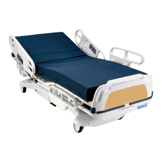
Page 5: D Bed Illustration
Bed Illustration HEAD END CPR Release Handle Siderail Release Handle Footboard Control Panel Steer Pedal Chart Rack (Optional Equip.) Motion Interrupt I.V. and Brake Pedal Fracture Frame Mount Foley Bag Hook FOOT END (Isolated) Foley Bag Hooks (Optional Equip.) (Standard) I.V. -
Page 6: Brake Pedal Operation
Base Operation Guide BRAKE PEDAL OPERATION WARNING Before putting a patient on the bed, be sure the brakes are fully engaged. To activate the brakes, push down once on the pedal identified by the label at right (located at both sides of the bed). -
Page 7: Cpr Emergency Release Usage
Litter Operation Guide CPR EMERGENCY RELEASE USAGE When quick access to the patient is needed, and the Fowler is raised, squeeze one of the two red release handles (see illustration, page 4) and the Fowler can be guided down to a flat position. NOTE The handle can be released at any time to stop lowering the Fowler. -
Page 8: I.v. Poles
Litter Operation Guide I.V. POLES To use the Permanently Attached I.V. pole (optional equipment): 1. Lift and pivot the pole from the storage position and push down until it is locked into receptacle (D). 2. To raise the height of the pole, turn the lock actuator (A) counter– clockwise and pull up on the telescoping portion (B) of the pole to raise it to the desired height. -
Page 9: Night Light Usage (Optional Equipment)
Litter Operation Guide NIGHT LIGHT USAGE (Optional Equipment) The bed may be equipped with an optional night light (A) that will illuminate the floor area around the bed. The light has three set– tings: LOW–OFF–HIGH. FOOT END PATIENT RESTRAINT STRAP LOCATIONS The bed is equipped with 12 separate locations for installing patient restraint straps. -
Page 10: D Foot Board/Head Board Chart Rack Usage, Foot Board (Optional Equipment)
Foot Board/Head Board Operation Guide CHART RACK USAGE (Optional Equipment) If the bed is equipped with the optional chart rack, it is located on the foot board. To use, pull handle rod (A) downward. To store, push the handle back to its storage position until it locks in place. -
Page 11: Control Panel Guide, Foot Board
Foot Board/Head Board Operation Guide FOOT BOARD CONTROL PANEL GUIDE 1. Push to turn on siderail control panel lights. Push again to turn off (see page 13). 2. Push to lock out all bed motions. Push again to unlock (see page 20). 3. - Page 12 Foot Board/Head Board Operation Guide FOOT BOARD CONTROL PANEL GUIDE (Continued) 1. Push to turn the Dynamic Mattress system on or off (see page 20). 2. Push to activate automatic or manual modes (see page 20). " This panel is optional equipment. AUTO SCALE 1.
-
Page 13: Led Display Panel Guide, Foot Board
Foot Board/Head Board Operation Guide LED DISPLAY PANEL GUIDE The LED Display Panel is located at the foot end of the bed, under the Control Panel. POWER BED MOTION LOCKED BRAKE NOT SET BED EXIT ON AIR LOSS ”POWER” – will light when the bed is plugged into the wall receptacle. ”BED MOTION LOCKED”... -
Page 14: Positioning Siderails
Siderail Operation Guide POSITIONING SIDERAILS NOTE The siderails can be locked at two heights (intermediate & full). The siderails can be tucked away under the bed when not in use. To remove the rail from the tucked position, grasp at the top of the rail and pull outward. -
Page 15: Inside Siderail Function Guide
Siderail Operation Guide INSIDE SIDERAIL FUNCTION GUIDE (Patient’s Right Rail) 1. Push to raise Knee Gatch. 2. Push to raise Fowler. 3. Push to lower Knee Gatch. 4. Push to lower Fowler. (Patient’s Left Rail) 1. Push to raise Fowler. 2. -
Page 16: Outside Siderail Function Guide
Siderail Operation Guide OUTSIDE SIDERAIL FUNCTION GUIDE (Patient’s Right Rail) 1. Push to raise Fowler. 2. Push to raise Knee Gatch. 3. Push to lower Fowler. 4. Push to lower Knee Gatch. " This panel is optional equipment. (Patient’s Left Rail) 1. -
Page 17: Weigh System Usage (Optional Equipment)
Weigh System Usage OPERATING THE SCALE BEFORE PUTTING A NEW PATIENT IN BED Prepare bed for patient stay (linens, pillows, etc.). Press and release ”SCALE ON”. The scale monitor will read: ”WEIGHING” ”XXX.X LB” Press and hold ”ZERO”. The scale monitor will read: ”HOLD TO ZERO WT.”... - Page 18 Weigh System Usage CONVERTING THE PATIENT’S WEIGHT To convert the patient’s weight from pounds to kilograms, press and release ”SCALE ON” to activate the weigh system. After the scale monitor reads ”XXX.X LB”, press and release the ”LBS/KGS” but- ton. The scale monitor will read: ”WEIGHT NOW KGS”...
-
Page 19: Weigh System Control Panel Guide (Optional Equipment)
Weigh System Control Panel Guide SYMBOL ACTION DISPLAY To prepare bed for new patient: Press and release ”SCALE ON” ”WEIGHING...” SCALE to activate the scale system, begin ”XXX.X LB” a new function and to display patient weight. Press and hold ”ZERO” ”HOLD TO ZERO WT.”... - Page 20 Weigh System Control Panel Guide SYMBOL ACTION DISPLAY To change the numerical value of displayed weight: Press and hold to scroll to ”HOLD TO DEC. WT.” desired weight. ”XXX.X LB” Press and hold to scroll to ”HOLD TO INC. WT.” desired weight.
-
Page 21: Bed Exit System Usage (Optional Equipment)
System Operation Guide ”BED EXIT” SYSTEM USAGE (Optional Equipment) 1. Before putting a new patient on the bed: prepare bed for patient stay by adding linens and equipment to the bed. Press and hold ”DISARM” key for 5 seconds – ”ARMED” light will begin to flash. Release ”DIS- ARM”... -
Page 22: D Limited Warranty Obtaining Parts And Service
420 Alcott Street, Kalamazoo, MI 49001 DH 7/93 3000–000–021 REV __...
Need help?
Do you have a question about the 3000 and is the answer not in the manual?
Questions and answers