Stryker Secure 3000 Maintenance Manual
Bed
Hide thumbs
Also See for Secure 3000:
- Maintenance manual (249 pages) ,
- Operation manual (29 pages) ,
- Operation manual (22 pages)

Related Manuals for Stryker Secure 3000


Summary of Contents for Stryker Secure 3000
- Page 1 IMPORTANT File in your maintenance records Secure 3000 Bed MAINTENANCE MANUAL For Parts or Technical Assistance 1–800–327–0770...
-
Page 2: Table Of Contents
Table of Contents Introduction Specifications ................Warning / Caution / Note Definition . - Page 3 Table of Contents Maintenance Procedures (Continued) Lift Motor Coupler Replacement ............64, 65 Lift Potentiometer Replacement and Adjustment .
- Page 4 Table of Contents Assembly Drawings and Parts Lists (Continued) Litter Assembly, HWI w/Communication and Ports Option ......151–153 Litter Assembly, HWI Communication Capability Option .
-
Page 5: Introduction
Introduction INTRODUCTION This manual is designed to assist you with the maintenance of the Secure 3000 Bed. Read it thoroughly be- fore beginning any maintenance on the equipment. SPECIFICATIONS Maximum Weight Capacity 500 pounds (227 kilograms) Overall Bed Length/Width 93” / 42–1/2”... -
Page 6: Safety Tips And Guidelines
WARNING The Secure 3000 Bed is not intended for use with patients less than two years of age. Powered bed mechanisms can cause serious injury. Operate bed only when all persons are clear of the mechanisms. -
Page 7: Limited Warranty
Stryker, found to be defective. Stryker warrants to the original purchaser that the frame and welds on its beds will be free from structural defects for as long as the original purchaser owns the bed. If requested by Stryker, products or parts for which a warranty claim is made shall be returned prepaid to Stryker’s factory. -
Page 8: Return Authorization
Claim will be limited in amount to the actual replacement cost. In the event that this information is not received by Stryker within the fifteen (15) day period following the delivery of the merchandise, or the damage was not noted on the delivery receipt at the time of receipt, the customer will be responsible for pay- ment of the original invoice in full. -
Page 9: Replacement Parts List
Replacement Parts List ELECTRICAL COMPONENTS LITTER CPU (SCALE AND BED EXIT) 3001–307–910 LITTER CPU (NON–SCALE) 3001–300–900 POWER BOARD 3001–300–910 SERIAL IFC 3000–300–965 HEADWALL IFC 3001–303–900 DMS POWER SUPPLY 3000–302–939 FOOT BOARD KEYBOARD (S/R LIGHTS, LOCKOUTS, ETC.) 3001–500–900 FOOT BOARD SCALE DISPLAY 3001–507–900 FOOT BOARD SCALE KEYBOARD 3001–507–910... -
Page 10: Preventative Maintenance
CAUTION Do not steam clean or hose off the Secure 3000. Do not immerse any part of the bed. Some of the internal parts of the bed are electric and may be damaged by exposure to water. -
Page 11: Maintenance Checklist
Preventative Maintenance REMOVAL OF IODINE COMPOUNDS This solution may be used to remove iodine stains from mattress cover and foam surfaces. 1. Use a solution of 1–2 tablespoons Sodium Thiosulfate in a pint of warm water to clean the stained area. Clean as soon as possible after staining occurs. -
Page 12: Set-Up Procedures
Set–Up Procedures SET–UP PROCEDURES It is important that the Secure 3000 Bed is working properly before it is put into service. The following list will help ensure that each part of the bed is tested. Plug the bed into a properly grounded, hospital grade wall receptacle and ensure the ”Power” LED light at the foot end of the bed comes on. -
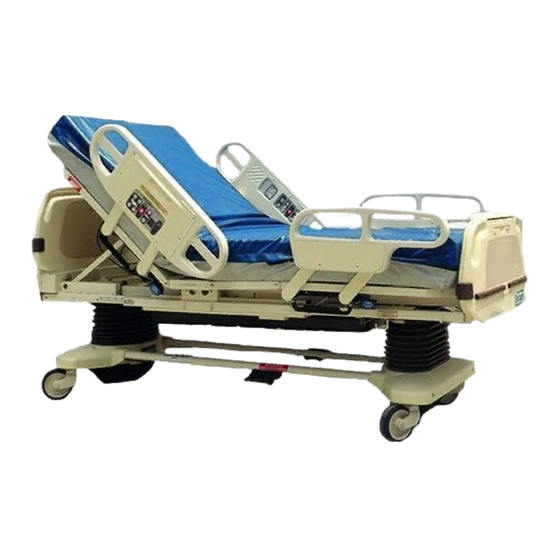
Page 13: Bed Illustration
Bed Illustration CPR Release Handle HEAD END PATIENT’S LEFT PATIENT’S RIGHT DMS Port Connector (Under Seat Section) Footboard Control Panel Siderail Release Handle Steer Pedal Chart Rack (Optional Equip.) Motion Interrupt Brake Pedal I.V. and Fracture Frame Mount FOOT END Night Foley Bag Hook Light... -
Page 14: Brake Pedal Operation
Base Operation Guide BRAKE PEDAL OPERATION WARNING Before putting a patient on the bed, be sure the brakes are fully engaged. To activate the brakes, push down once on the pedal identified by the label at right (located at the midpoint of the bed on both sides). -
Page 15: Cpr Emergency Release Usage
Litter Operation Guide CPR EMERGENCY RELEASE USAGE When quick access to the patient is needed, and the Fowler is raised, squeeze one of the two red release handles (see illustration, page 12) and the Fowler can be guided down to a flat position. NOTE The handle can be released at any time to stop the Fowler from lowering. -
Page 16: I.v. Poles
Litter Operation Guide I.V. POLES To use the Permanently Attached I.V. pole (optional equipment): 1. Lift and pivot the pole from the storage position and push down until it is locked into receptacle (A). 2. To raise the height of the pole, turn the lock actuator (B) counter– clockwise and pull up on the telescoping portion (C) of the pole to raise it to the desired height. -
Page 17: Night Light Usage
Litter Operation Guide NIGHT LIGHT USAGE (Optional Equipment) The bed may be equipped with an optional night light (A) that will illuminate the floor area around the bed. The light has three set- tings: LOW–OFF–HIGH FOOT END PATIENT RESTRAINT STRAP LOCATIONS The bed is equipped with 12 separate locations for installing patient restraint straps. -
Page 18: Chart Rack Usage
Head Board/Foot Board Operation Guide CHART RACK USAGE (Optional Equipment) If the bed is equipped with the optional chart rack, it is located on the foot board. To use, pull handle rod (A) downward. To store, push the handle back to its storage position until it locks in place. -
Page 19: Positioning Siderails
Siderail Operation Guide POSITIONING SIDERAILS NOTE The siderails can be locked at two heights (intermediate & full). The siderails can be tucked away under the bed when not in use. To remove the rail from the tucked position, grasp the top of the rail and pull outward. To engage the head end siderail, grasp the rail and swing it upward toward the head end of the bed until it rests in the ”intermediate”... -
Page 20: Inside Siderail Function Guide
Siderail Operation Guide INSIDE SIDERAIL FUNCTION GUIDE (Patient’s Right Rail) 1. Push to raise Knee Gatch. 2. Push to lower Knee Gatch. 3. Push to raise Fowler. 4. Push to lower Fowler. (Patient’s Left Rail) 1. Push to raise Fowler. 2. -
Page 21: Outside Siderail Function Guide
Siderail Operation Guide OUTSIDE SIDERAIL FUNCTION GUIDE (Patient’s Right Rail) 1. Push to raise Fowler. 2. Push to lower Fowler. 3. Push to raise Knee Gatch. 4. Push to lower Knee Gatch. " This panel is optional equipment. (Patient’s Left Rail) 1. -
Page 22: Dynamic Mattress System Usage
Siderail Operation Guide OUTSIDE SIDERAIL FUNCTION GUIDE (CONTINUED) Push to activate auto or manual mode of the Dynamic Mattress System. LED will light to indicate selected mode and/or possible air leak. " This panel is optional equipment. DYNAMIC MATTRESS SYSTEM USAGE (OPTIONAL EQUIPMENT) 1. -
Page 23: Foot Board Control Panel Guide
Foot Board Operation Guide FOOT BOARD CONTROL PANEL GUIDE 1. Push repeatedly for low, medium and high settings for siderail control lights. Pushing a fourth and fifth time will turn off the siderail control lights and the red nurse call light respectively (see page 18). CAUTION The intent of the red nurse call light on the siderails is to ensure the patient has immediate understanding of which button to push to contact the nurse station. -
Page 24: Foot Board Control Panel Guide
Foot Board Operation Guide FOOT BOARD CONTROL PANEL GUIDE (CONTINUED) 1. Push to raise Fowler. 2. Push to raise Knee Gatch. 3. Push to lower Fowler. 4. Push to lower Knee Gatch. " This panel is optional equipment. LED DISPLAY PANEL GUIDE The LED Display Panel is located at the foot end of the bed, under the Control Panel. - Page 25 Foot Board Operation Guide CENTER OF GRAVITY BED EXIT (OPTIONAL EQUIPMENT) 1. Push to activate Bed Exit function. 2. Push to deactivate Bed Exit function. NOTE If the scale system is in use, it will switch to ”off” when Bed Exit is armed. Bed Exit will be temporarily disarmed when the scale system is activated and will re–arm when the scale system shuts off.
-
Page 26: Weigh System Operation Guide
Foot Board Operation Guide WEIGH SYSTEM CONTROL PANEL GUIDE 1. LCD – displays patient weight. 2. Push to zero bed. 3. Push when changing equipment on the bed. 4. Push to change weight from pounds to kilograms or back. 5. Push to turn weight system on. 6. - Page 27 Foot Board Operation Guide WEIGH SYSTEM CONTROL PANEL GUIDE (CONTINUED) SYMBOL ACTION DISPLAY To add or remove equipment during patient stay without affecting registered patient weight: Press and release ”SCALE ON” ”WEIGHING...” ”XXX.X LB” Press ”HOLD TO START” ”RELEASE TO START” Release ”DO NOT TOUCH BED”...
- Page 28 Weigh System Usage OPERATING THE SCALE BEFORE PUTTING A NEW PATIENT IN BED Prepare bed for patient stay (linens, pillows, etc.). Press and hold ”SCALE ON”. Release the button after the display reads ”LET GO FOR SCALE”. (This will turn off the Trend. angle display and activate the scale). The scale monitor will read: ”LET GO FOR SCALE”...
- Page 29 Weigh System Usage CONVERTING THE PATIENT’S WEIGHT To convert the patient’s weight from pounds to kilograms, press and release ”SCALE ON” to activate the weigh system. After the scale monitor reads ”XXX.X LB”, press and release the ”LBS/KGS” but- ton. The scale monitor will read: ”WEIGHT NOW KGS”...
-
Page 30: Static Discharge Precautions
2 and 3 of the following procedure. Do not place unprotected circuit boards on the floor. All circuit boards to be returned to Stryker Medical should be shipped in the static shielding bags the new boards were shipped in. -
Page 31: Troubleshooting
Troubleshooting The Secure 3000 has only two main printed circuit boards in the litter (a CPU and a power PCB), two switch boards in each siderail, and one interface switch board at the foot board. Because of this design, isolating a “board failure”... -
Page 32: Troubleshooting Guide
Troubleshooting Guide SIDERAILS Each siderail contains an outside and and inside switch board. Power to the siderails is provided by the CPU board. Determine if the problem exists only in one siderail or in both siderails. A.) If the problem is isolated to one siderail, switch the siderail connectors on the CPU. If the problem is trans- ferred to the other siderail, and the “bad”... -
Page 33: Troubleshooting
Troubleshooting Guide FOWLER AND KNEE LIFT The heights of the Fowler and Knee are adjusted by separate motors located directly under the Fowler and the Knee. The motors are coupled to a worm gear that moves the Fowler or Knee up or down. When the Fowler or Knee button on either the foot board or siderail is pressed, the signal passes through the CPU and into the power board, activating a relay on the power board, and energizing the Fowler or Knee motor from the power board. - Page 34 37 pin connector for the interface cable between the bed and the wall system. The signal is a momentary switch closure and does not contain voltage. Stryker is responsible for the successful interface between the bed and the existing system. Stryker is not responsible for the nurse call system installation or modifications to the current system.
-
Page 35: Bed Component And Wiring Diagram
Bed Component and Wiring Diagram... - Page 36 Bed Component and Wiring Diagram...
- Page 37 Bed Component and Wiring Diagram Item Part No. Part Name 3000–300–820 Power Cord Assembly 3001–303–900 Head Wall IFC Board 3000–303–871 Battery (Nurse Call Backup) 3001–307–53 Load Cell Load Cell Connectors 3001–300–910 Power Board 3001–300–703 Head Motor 3000–300–453 Capacitor 3001–307–910 CPU Board (Scale and Bed Exit) 3001–300–900 CPU Board (Non–Scale) 3000–300–58...
- Page 38 Notes...
- Page 39 Bed Component and Wiring Diagram...
- Page 40 Bed Component and Wiring Diagram...
- Page 41 Bed Component and Wiring Diagram Item Part No. Part Name 3001–300–804 Power PCB/CPU Control Cable 3001–307–812 Head End Load Cell Cable 3000–300–820 Power Cord (Comes w/Motor) Fowler Motor and Capacitor Cabling 3001–300–805 Litter Pot Cable (Foot End Bed Lift Pot & Head & Foot End Motion Interrupt Switches) 3001–300–824 Litter Signal Coil Cord (Fowler &...
- Page 42 Bed Component and Wiring Diagram...
-
Page 43: Bed Circuit Boards
Bed Circuit Boards CPU BOARD PCB – P/N 3001–307–910 NOTE 12 VDC is unregulated so 12V readings will actually be 16 to 18 VDC. CONNECTOR CABLE VOLTAGE POSITIVE NEGATIVE DESCRIPTION LOCATION LOCATION LEAD LEAD HDR 10 5 VDC Pin 12 HDR 12 Foot Board Pin 6... - Page 44 Bed Circuit Boards CPU BOARD PCB – P/N 3001–307–910 (CONTINUED) CONNECTOR CABLE VOLTAGE POSITIVE NEGATIVE DESCRIPTION LOCATION LOCATION LEAD LEAD HDR 25 –5 VDC Pin 8 HDR 16 Head End Load Pin 1 Cells HDR 25 5 VDC Pin 7 HDR 16 Head End Load Pin 1...
- Page 45 Bed Circuit Boards CPU BOARD PCB – P/N 3001–307–910 (CONTINUED) CONNECTOR CABLE VOLTAGE POSITIVE NEGATIVE DESCRIPTION LOCATION LOCATION LEAD LEAD HDR 14 3.3 VDC Pin 12 Pin 1 Left Siderail HDR 14 10 VDC Pin 6 Pin 1 Left Siderail HDR 14 5 VDC Pin 5...
- Page 46 Bed Circuit Boards CPU BOARD PCB – P/N 3001–307–910 (CONTINUED) CONNECTOR CABLE VOLTAGE POSITIVE NEGATIVE DESCRIPTION LOCATION LOCATION LEAD LEAD HDR 16 5 VDC (w/switch) Pin 20 Pin 1 Power Board 0 VDC (w/o (Foot End Bed Up) switch) HDR 16 5 VDC (w/switch) Pin 19 Pin 1...
- Page 47 Bed Circuit Boards HEADWALL INTERFACE PCB – P/N 3001–303–900 CONNECTOR CABLE VOLTAGE POSITIVE NEGATIVE DESCRIPTION LOCATION LOCATION LEAD LEAD HDR 1 16–18 VDC (w/o Pin 1 Pin 3 Nurse Call switch) Minimal Volt Drop (w/ switch) HDR 1 16–18 VDC (w/o Pin 2 Pin 3 Nurse Call...
- Page 48 Bed Circuit Boards 37–PIN CONNECTOR Pin 1 Option 2 Common Pin 2 Read Light Pin 3 Room Light Pin 4 Speaker High Pin 5 Pot Wiper Pin 6 Radio Common Pin 7 Nurse Call Interlock Pin 8 Audio Transfer – Pin 9 Audio Transfer + Pin 10...
- Page 49 Bed Circuit Boards HEAD WALL INTERFACE W/STRYKER PORT PCB – P/N 3001–314–900 CONNECTOR CABLE VOLTAGE POSITIVE NEGATIVE DESCRIPTION LOCATION LOCATION LEAD LEAD HDR 1 16–18 VDC (w/o Pin 1 Pin 3 Nurse Call switch) Minimal Volt Drop (w/ switch) HDR 1 16–18 VDC (w/o...
- Page 50 Bed Circuit Boards POWER BOARD PCB – P/N 3001–300–910 CONNECTOR CABLE VOLTAGE POSITIVE NEGATIVE DESCRIPTION LOCATION LOCATION LEAD LEAD HDR 3 0 VDC (w/o switch) 5 Pin 22 Pin 1 Head End Bed Up VDC (w/ switch) HDR 3 0 VDC (w/o switch) 5 Pin 21 Pin 1 Head End Bed Down...
- Page 51 Bed Circuit Boards POWER BOARD PCB – P/N 3001–300–910 (CONTINUED) CONNECTOR CABLE VOLTAGE POSITIVE NEGATIVE DESCRIPTION LOCATION LOCATION LEAD LEAD HDR 4 0 VAC (w/o switch) Pin 2 Pin 3 Head End Bed Motor 110 VAC (w/ switch) Down HDR 7 0 VAC (w/o switch) Pin 1 Pin 3...
- Page 52 Bed Circuit Boards DMS POWER SUPPLY PCB CONNECTOR VOLTAGE POSITIVE NEGATIVE DESCRIPTION LOCATION LEAD LEAD 110 VAC Main Power 110 VAC Main Power 24 VDC To DMS Port Fuse 1 .3A 3AG Slo Blo Fuse 2 .3A 3AG Slo Blo...
- Page 53 Bed Circuit Boards SERIAL INTERFACE PCB – P/N 3000–300–965 CONNECTOR CABLE VOLTAGE POSITIVE NEGATIVE DESCRIPTION LOCATION LOCATION LEAD LEAD No cable location 9 VDC Pin 1 Pin 2 DMS Port No cable location 9 VDC Pin 3 Pin 2 DMS Port No cable location 9 VDC Pin 4...
-
Page 54: Maintenance Procedures
Maintenance Procedures – Base BRAKE PEDAL REPLACEMENT Required Tools: 5/16” Hex Allen Wrench Torque Wrench Loctite 242 Hammer Punch #2 Phillips Screwdriver Procedure: 1. Unplug the bed power cord from the wall socket. 2. Using a #2 Phillips screwdriver, remove the three screws holding both the head end and the foot end up- per lift covers. -
Page 55: Brake Sensor Replacement
Maintenance Procedures – Base BRAKE SENSOR REPLACEMENT Required Tools: 5/16” Socket Wrench Side Cutters 5/16” Open End Wrench HEAD END Procedure: 1. Unplug the power cord from the wall socket. Using a 5/16” socket, remove the six bolts holding the lower lift cover to the base. -
Page 56: Steer Wheel Cable Replacement And Adjustment
Maintenance Procedures – Base STEER WHEEL CABLE REPLACEMENT AND ADJUSTMENT Required Tools: 5/16” Socket Wrench (2) 5/16” Nut Drivers Needle–Nose Vise Grip Pliers Standard Screwdriver (2) 10 mm Open End Wrenches 3/8” Socket Wrench (2) 3/16” Hex Socket Drivers FOOT END HEAD END 1. - Page 57 Maintenance Procedures – Base STEER WHEEL CABLE REPLACEMENT AND ADJUSTMENT (CONTINUED) 6. Using two 3/16” hex socket drivers, loosen the bolt in the cable retainer (E) and slide the retainer off the cable. Pull the cable out of the bed. NOTE If the cable sheathing is not damaged, pull the cable from the head end of the bed and remove it from the sheathing, leaving the sheathing on the bed.
- Page 58 Maintenance Procedures – Base STEER WHEEL CABLE REPLACEMENT AND ADJUSTMENT (CONTINUED) 3/16” Adjustment Procedure: If the steer wheel engages when the steer pedal is in the neutral or off position, slide the cable retainer toward the cable support bracket and tighten the retainer back down on the cable. If the steer wheel does not hold properly when the pedal is in the steer position, slide the retainer away from the cable support bracket and tighten the retainer back down on the cable.
-
Page 59: Caster Replacement
Maintenance Procedures – Base CASTER REPLACEMENT Required Tools: Floor Jack 1/2” Socket w/extension #2 Phillips Screwdriver Bungee Cord (or equivalent) Wooden Brace FOOT END BOTTOM VIEW Replacement Procedure: 1. Unplug the power cord from the wall socket. 2. Using a #2 Phillips screwdriver, remove the three screws holding the upper lift cover to the base. 3. -
Page 60: Lift Motor And Capacitor Removal And Replacement
Maintenance Procedures – Base LIFT MOTOR AND CAPACITOR REMOVAL AND REPLACEMENT Required Tools: 3/16” Hex Allen Socket 5/16” Socket Wrench #2 Phillips Screwdriver 7/16” Open End Wrench Side Cutters Bungee Cord (or equivalent) FOOT END Procedure: 1. Unplug the power cord from the wall socket. Using a 5/16” socket wrench, remove the six bolts holding the lower lift cover to the base and remove the cover. -
Page 61: Lift Motor Isolation Plate Replacement
Maintenance Procedures – Base LIFT MOTOR ISOLATION PLATE REPLACEMENT Required Tools: #2 Phillips Screwdriver 1/4” Nut Driver 3/8” Open End Wrench 3/8” Socket Wrench 3/16” Punch Hammer Needle–Nose Pliers 5/16” Nut Driver 7/16” Open End Wrench 3/16” Hex Allen Socket (w/6” ext.) 5/16”... -
Page 62: Lift Motor Isolation Plate Replacement
Maintenance Procedures – Base LIFT MOTOR ISOLATION PLATE REPLACEMENT (CONTINUED) 6. Remove the motor coupler (D) and bushings (E) through the access holes. 7. Using a 3/16” punch and hammer, remove the top roll pin on the manual drive hex shaft coupling and set the shaft and coupler assembly aside. -
Page 63: Lift Housing Removal And Replacement
Maintenance Procedures – Base LIFT HOUSING REMOVAL AND REPLACEMENT Required Tools: Standard Screwdriver Phillips Screwdriver Bungee Cord (or equivalent) 5/16” Socket Wrench 9/16” Socket Wrench Needle–Nose Vise Grip Pliers 3/8” Open End Wrench Small Standard Screwdriver 5/16” Open End Wrench Side Cutters 5/16”... - Page 64 Maintenance Procedures – Base LIFT HOUSING REMOVAL AND REPLACEMENT (CONTINUED) FOOT END – BOTTOM VIEW 9. Lift the litter top up and support it about 6” above the lift screws with sawhorses or the equivalent. 10. Under the base, using a 9/16” socket, remove the four nuts (B) holding the lift housing to the base. 11.
-
Page 65: Lift Motor Coupler Replacement
Maintenance Procedures – Base LIFT MOTOR COUPLER REPLACEMENT Required Tools: #2 Phillips Screwdriver Bungee Cord (or equivalent) 5/16” Socket Wrench 5/16” Nut Driver 1/2” Socket (w/extension) FOOT END – BOTTOM VIEW Procedure: 1. Unplug the bed power cord from the wall socket. 2. - Page 66 Maintenance Procedures – Base LIFT MOTOR COUPLER REPLACEMENT (CONTINUED) 5. Using a 5/16” nut driver, remove the two screws (C) holding the metal access panel (D) to the lift housing. 6. The motor coupler (E) can now be removed from the lift housing through the access hole. 7.
-
Page 67: Lift Potentiometer Replacement And Adjustment
Maintenance Procedures – Base LIFT POTENTIOMETER REPLACEMENT AND ADJUSTMENT Required Tools: Small Standard Screwdriver #2 Phillips Screwdriver Bungee Cord (or equivalent) 5/16” Socket Wrench 3/8” Open End Wrench Side Cutters Procedure: 1. Unplug the bed power cord from the wall socket. 2. -
Page 68: Lift Potentiometer "Burn-In" Procedure
Maintenance Procedures – Base LIFT POTENTIOMETER REPLACEMENT AND ADJUSTMENT (CONTINUED) 8. Lift up and out on the pot housing assembly to remove it from the lift housing. 9. Before installing the new pot on the bed, turn it clockwise until it stops. Turn it back counterclockwise two full (360_) revolutions. -
Page 69: Power And Sensor Coil Cord Replacement
Maintenance Procedures – Base POWER AND SENSOR COIL CORD REPLACEMENT Required Tools: #2 Phillips Screwdriver Side Cutters Bungee Cord (or equivalent) 5/16” Nut Driver 5/16” Socket Wrench Procedure: 1. Unplug the bed power cord from the wall socket. 2. Using a 5/16” socket wrench, remove the six bolts holding the lower lift cover to the base and remove the cover. - Page 70 Maintenance Procedures – Base POWER AND SENSOR COIL CORD REPLACEMENT ILLUSTRATION VIEW FROM CENTER OF BED...
-
Page 71: Motion Interrupt Switch Replacement
Maintenance Procedures – Litter MOTION INTERRUPT SWITCH REPLACEMENT Required Tools: #2 Phillips Screwdriver 5/16” Nut Driver 3/8” Socket Wrench T27 Torx NOTE Because of fastener changes, it will be necessary to use either a 3/8” socket wrench or a T27 Torx to remove the bolts holding the ground straps to the motion interrupt pan and a Phillips screwdriver or a T27 Torx to remove the bolts securing the litter access panels. -
Page 72: Knee Motor Limit Setting
Maintenance Procedures – Litter LIMIT SETTING – KNEE MOTOR Required Tools: 5/16” Nut Driver 3/8” Socket Wrench or T27 Torx NOTE Because of fastener changes, it will be necessary to use either a 3/8” socket wrench or a T27 Torx to remove the bolts holding the ground straps to the motion interrupt pan. -
Page 73: Cam And Cam Guide Replacement - Head And Knee Motors
Maintenance Procedures – Litter CAM AND CAM GUIDE REPLACEMENT – HEAD AND KNEE MOTOR Required Tools: 5/16” Nut Driver 7/16” Nut Driver #2 Phillips Screwdriver 7/16” Open End Wrench 3/8” Socket Wrench or T27 Torx NOTE Because of fastener changes, it will be necessary to use either a 3/8” socket wrench or a T27 Torx to remove the bolts holding the ground straps to the motion interrupt pan and a Phillips screwdriver or a T27 Torx to remove the bolts securing the litter access panels. -
Page 74: Cam And Cam Guide Replacement – Head And Knee Motors
Maintenance Procedures – Litter CAM AND CAM GUIDE REPLACEMENT – HEAD AND KNEE MOTOR (CONTINUED) 5. If the head motor cam and cam guide are being replaced, use a 5/16” nut driver to remove the screw (A) holding the cam retention wire to the ball nut assembly. If the knee motor cam and cam guide are being replaced, use a 7/16”... -
Page 75: Knee Motor Drive Screw And Nut Replacement
Maintenance Procedures – Litter DRIVE SCREW AND NUT REPLACEMENT – KNEE MOTOR Required Tools: 5/16” Nut Driver 1/4” Nut Driver Hammer Hex Allen Wrench Side Cutters 7/16” Open End Wrench 7/16” Socket Wrench 1/8” Punch 6” Extension... - Page 76 Maintenance Procedures – Litter DRIVE SCREW AND NUT REPLACEMENT – KNEE MOTOR (CONTINUED) Procedure: 1. Remove the knee motor (see page 76). 2. Unhook hitch pin (K) from the knee section. 3. Using a 7/16” socket and 7/16” open end wrench, remove the nut, bolt and washer (F) holding the drive screw nut and the cam wire link to the main link (G).
-
Page 77: Knee Motor Removal And Replacement
Maintenance Procedures – Litter KNEE MOTOR REMOVAL AND REPLACEMENT Required Tools: 5/16” Nut Driver 1/4” Nut Driver 3/8” Socket Wrench 1/8” Hex Allen Wrench #2 Phillips Screwdriver Wire Cutters T27 Torx Procedure: 1. Electrically run the knee section (Gatch) fully up. Unplug the power cord from the wall receptacle. 2. -
Page 78: Head Motor Limit Setting
Maintenance Procedures – Litter LIMIT SETTING – HEAD MOTOR Required Tools: #2 Phillips Screwdriver 5/16” Nut Driver 7/16” Open End Wrench 7/16” Socket 3/8” Socket Wrench or T27 Torx NOTE Because of fastener changes, it will be necessary to use either a 3/8” socket wrench or a T27 Torx to remove the bolts holding the ground straps to the motion interrupt pan and a Phillips screwdriver or a T27 Torx to remove the bolts securing the litter access panels. -
Page 79: Head Motor Removal And Replacement
Maintenance Procedures – Litter HEAD MOTOR REMOVAL AND REPLACEMENT Required Tools: Side Cutters 5/16” Nut Driver 7/16” Socket Wrench 3/8” Socket Wrench #2 Phillips Screwdriver T27 Torx NOTE Because of fastener changes, it will be necessary to use either a Phillips screwdriver or a T27 Torx to remove the bolts securing the litter access panel. -
Page 80: Head Motor Removal And Replacement
Maintenance Procedures – Litter HEAD MOTOR REMOVAL AND REPLACEMENT 6. Unplug the head motor cable (B) from the bed and capacitor. WARNING Support the head section with a wooden brace (2 x 4 or equivalent) before continuing or personal injury could result. -
Page 81: Head Motor Drive Isolator And Cpr Decoupler Removal And Replacement
Maintenance Procedures – Litter HEAD MOTOR DRIVE ISOLATOR AND CPR DECOUPLER REMOVAL AND REPLACEMENT Required Tools: 5/16” Nut Driver #2 Phillips Screwdriver 3/8” Socket Wrench 7/16” Socket Wrench Wire Cutter Procedure: 1. Refer to page 78 for ”Head Motor Removal and Replacement” to access the isolator, springs and decoup- ler. -
Page 82: Head Motor Drive Screw And Ball Nut Replacement
Maintenance Procedures – Litter DRIVE SCREW AND BALL NUT REPLACEMENT – HEAD MOTOR Required Tools: 1/4” Nut Driver 5/16” Nut Driver 7/16” Socket Wrench Needle–Nose Pliers 7/16” Open End Wrench (2) 3/8” Socket Wrench or T27 Torx NOTE Because of fastener changes, it will be necessary to use either a 3/8” socket wrench or a T27 Torx to remove the bolts holding the ground straps to the motion interrupt pan. - Page 83 Maintenance Procedures – Litter DRIVE SCREW AND BALL NUT REPLACEMENT – HEAD MOTOR (CONTINUED) 7. Remove the clevis pin and slide the wing and tapered roller bearing off the drive screw. 8. Using a 5/16” nut driver underneath the litter, remove the screw holding the cam retention wire (B) to the ball nut assembly.
-
Page 84: Cpr Cable Adjustment And Replacement
Maintenance Procedures – Litter CPR CABLE ADJUSTMENT/REPLACEMENT Required Tools: Needle–Nose Pliers (2) 10 mm Open–End Wrenches NOTE The CPR emergency release allows quick access to the patient when the head section is raised. When han- dle (A) is squeezed, the attached cable (B) pulls the CPR bracket (C) which pulls the motor coupler out of the drive screw and causes the head section to drop. - Page 85 Maintenance Procedures – Litter Area 1...
- Page 86 Maintenance Procedures – Litter VIEW 1 VIEW 2 TOP VIEW...
-
Page 87: Weigh System Diagnostic Procedure
Maintenance Procedures – Litter WEIGH SYSTEM DIAGNOSTIC PROCEDURE Diagnostic Mode Functions: 1. Calibrate Scale: This may be required in the field if the scale CPU is replaced. 2. Init. to Defaults: This may be required in the field when replacing the scale CPU board. 3. - Page 88 Maintenance Procedures – Litter Displaying Individual Load Cell Outputs: A defective load cell can be detected by entering diagnostics and displaying individual load cell outputs. 1. Enter the diagnostic mode. The scale monitor will display CALIBRATE when the diagnostic mode is ac- tive.
-
Page 89: Load Cell Replacement
Maintenance Procedures – Litter LOAD CELL REPLACEMENT Required Tools: #2 Phillips Screwdriver or T27 Torx 5/16” Nut Driver Side Cutters 1/4” Hex Allen Wrench HEAD END Procedure: 1. Unplug the bed power cord from the wall socket. 2. Using a #2 Phillips screwdriver or a T27 Torx, remove the four screws securing the litter access cover at the end of the bed needing service and remove the cover. - Page 90 Maintenance Procedures – Litter LOAD CELL REPLACEMENT (CONTINUED) 3. Using a 5/16” nut driver, remove the bolt holding the load cell cable connector cover and remove the cover. 4. Support the corner of the litter where the load cell is being removed. 5.
-
Page 91: Power Board Replacement
Maintenance Procedures – Litter POWER BOARD REPLACEMENT Required Tools: 1/4” Nut Driver #2 Phillips Screwdriver or T27 Torx Needle–Nose Pliers NOTE Because of fastener changes, it will be necessary to use either a Phillips screwdriver or a T27 Torx to remove the bolts securing the litter access panel. -
Page 92: Main Cpu Board "Burn-In" Procedure
Maintenance Procedures – Litter MAIN CPU BOARD “BURN–IN” PROCEDURE When the main CPU board has been changed, the lift potentiometers must be programmed into the CPU. Lift Potentiometer Programming 1. Unplug the power cord from the wall receptacle. 2. At the foot board push and hold down the Siderail Lights button, Fowler Lock Out button, and Bed Up/ Down button. -
Page 93: Power Cord Replacement
Maintenance Procedures – Litter POWER CORD REPLACEMENT Required Tools: Heyco Pliers #2 Phillips Screwdriver or T27 Torx Side Cutters 5/16” Nut Driver 1/4” Nut Driver NOTE Because of fastener changes, it will be necessary to use either a Phillips screwdriver or a T27 Torx to remove the bolts securing the litter access panel. -
Page 94: Siderail Cover Removal
Maintenance Procedures – Siderail HEAD AND FOOT SIDERAIL COVER REMOVAL Required Tools: #2 Phillips Screwdriver Removal Procedure: 1. Unplug the power cord from the wall receptacle. 2. Using a #2 Phillips screwdriver, remove the 8 phillips screws (A) holding the covers (B) to the siderail. CAUTION There are two cables connecting the outside cover to the head end siderail. -
Page 95: Molded Siderail Replacement
Maintenance Procedures – Siderail HEAD AND FOOT MOLDED SIDERAIL REPLACEMENT Required Tools: #2 Phillips Screwdriver 5/16” Nut Driver Procedure: 1. Unplug the bed power cord from the wall socket. 2. Remove the siderail cover (see page 93). 3. Using a 5/16” nut driver, remove the four screws (A) holding the molded rail (C) to the siderail support assembly (B). -
Page 96: Head End Siderail Cable Replacement
Maintenance Procedures – Siderail HEAD END SIDERAIL CABLE REPLACEMENT Required Tools: #2 Phillips Screwdriver or T27 Torx Side Cutters NOTE Because of fastener changes, it will be necessary to use either a Phillips screwdriver or a T27 Torx to remove the bolts securing the litter access cover. - Page 97 Maintenance Procedures – Siderail HEAD END SIDERAIL CABLE REPLACEMENT (CONTINUED) 6. Using a Phillips screwdriver, remove the two screws (E) holding the rear siderail pivot arm cover to the pivot arm. Remove the cover to expose the siderail cables. 7. Using side cutters, clip the cable ties (A) holding the cables together. 8.
-
Page 98: Siderail Assembly Removal
Maintenance Procedures – Siderail SIDERAIL ASSEMBLY REMOVAL Required Tools: #2 Phillips Screwdriver T27 Torx NOTE Because of fastener changes, it will be necessary to use either a Phillips screwdriver or a T27 Torx to remove the bolts securing the litter access cover. Removal Procedure: 1. -
Page 99: Foot Board Hinge Removal
Maintenance Procedures – Foot Board FOOT BOARD HINGE REMOVAL Required Tools: #2 Phillips Screwdriver Procedure: 1. Using a #2 Phillips screwdriver, remove the screws (A) holding the door and hinge assembly to the foot board. 2. If replacing the hinge only, use a Phillips screwdriver to remove the screws holding the hinge to the door. 3. -
Page 100: Foot Board Interface Plug Replacement
Maintenance Procedures – Foot Board FOOT BOARD INTERFACE PLUG REPLACEMENT Required Tools: #2 Phillips Screwdriver BOTTOM VIEW OF FOOT BOARD Procedure: 1. Unplug the bed power cord from the wall socket. 2. Remove the foot board from the bed to access the bottom of the board. 3. -
Page 101: Base Assembly
Base Assembly Assembly part number 3001–200–3 (reference only) FOOT END HEAD END... - Page 102 Base Assembly Assembly part number 3001–200–000 Brake Link Assembly Installation of Roll Pin (Typical Both Ends) into Brake Shaft Crank (Typical Four Places)
- Page 103 Base Assembly Assembly part number 3001–200–000 HEAD END...
- Page 104 Base Assembly Assembly part number 3001–200–000 HEAD END FOOT END HEAD END/FOOT END...
- Page 105 Base Assembly Assembly part number 3001–200–000 HEAD END/FOOT END (Typical Both Ends) HEAD END/FOOT END (Typical Both Ends) HEAD END/FOOT END (Typical Both Ends) HEAD END/FOOT END (Typical Both Ends)
- Page 106 Base Assembly Assembly part number 3001–200–000 HEAD END FOOT END...
-
Page 107: Base Assembly
Brake Bar Return Spring 3001–200–8 Bellows Bracket 3000–200–318 Guide Pin 3000–200–603 Steer Pedal Label AM 3000–200–324 Brake Bar Bumper 3000–200–602 Stryker Logo Label AN 16–35 Nylock Nut 988–2–708 Caution Label 3000–200–323 Brake Bar 3000–200–601 Brake Pedal Label AQ 3000–300–321 Brake Ring 3000–200–11... - Page 108 Assembly part number 3000–200–275 (reference only)
-
Page 109: Lift Assembly (Common)
Lift Assembly (Common) - Page 110 Lift Assembly (Common) Item Part No. Part Name Qty. 3000–200–201 Upper Lift Housing 3000–200–202 Lower Lift Housing 3000–200–251 Outer Screw 3000–200–204 Upper Housing Sleeve 3000–200–205 Upper Stage Nut 3000–200–249 Inner Screw 3000–200–207 Lower Stage Nut 3000–200–208 Glide Bushing 3000–200–209 Motor Pinion Gear 3000–200–210 Idler Gear 3000–200–252...
-
Page 111: Lift Assembly (Head End)
Lift Assembly (Head & Foot End) Assembly part numbers 3000–200–200 (Head) 3000–200–250 (Foot) Item Part No. Part Name Qty. (page 107–109) Common Lift Assembly 3000–200–217 Potentiometer Mtg. Brkt. 3–121 Hex Washer Hd. Screw 3000–200–807 Head Pot Cable 3000–200–806 Foot Pot Cable 3000–200–215 Potentiometer Worm Gear 3000–200–253... -
Page 112: Lift Assembly (Foot End)
Isolation Plate Assembly Assembly part number 3001–300–212 Item Part No. Part Name Qty. 3000–200–212 Isolation Plate 3000–200–228 Motor Mtg. Plate Grommet... -
Page 113: Litter Assembly
Litter Assembly Assembly part number 3001–300–001 Head End... - Page 114 Litter Assembly Assembly part number 3001–300–1 Foot End...
- Page 115 Assembly part number 3001–300–1...
- Page 116 Assembly part number 3001–300–1 Head End Bottom Side (Base Omitted for Clarity) Foot End – Bottom Side (Base Omitted for Clarity)
- Page 117 Assembly part number 3001–300–1 Detail A Litter Pivot Joints Typical (6) Places...
- Page 118 Detail C Litter Ground Jumper Frame to Thigh Litter Typical (2) Places Detail D Litter Ground Jumper BetweenThighandFootLitter Typical (2) Places Detail B Foot Prop Installation Typical (2) Places...
- Page 119 Detail E Litter Ground Jumper Typical (2) Places Detail F Fowler Link Bracket Attachment to Fowler Litter Typical (2) Places Detail G ShorterBed Configuration...
- Page 120 Fowler actuator cover and mid litter cover shown in phantom for clarity. Detail H Fowler Litter Bumper Typical (2) Places...
-
Page 121: Litter Assembly
Litter Assembly 3001–300–1 Litter Assembly – Common Components Item Part No. Part Name Qty. Item Part No. Part Name Qty. (page 134–140) Electrical Litter Ass’y 3001–300–99 Fowler Bushing 3000–300–349 11–303 Flat Washer 3000–300–350 Head End Bumper 16–16 Fiber Lock Nut 23–80 27–7 Cotter Pin... -
Page 122: Litter Assembly, Mechanical
Litter Assembly, Mechanical Assembly part number 3001–300–199... - Page 123 Assembly part number 3001–300–199...
- Page 124 Assembly part number 3001–300–199...
- Page 125 Assembly part number 3001–300–199...
-
Page 126: Litter Assembly, Mechanical
Litter Assembly, Mechanical 3001–300–199 Mechanical Litter Assembly – Common Components Item Part No. Part Name Qty. Item Part No. Part Name Qty. 3001–300–301 Stationary Frame Ass’y 16–6 Kep Nut 4–211 Soc. Hd. Cap Screw 52–800 Grommet 3000–300–353 Roller 23–251 Hex Washer Hd. Screw 3000–300–352 Roller Shaft 3001–300–320... -
Page 127: Fowler Limit Assembly
Fowler Limit Switch Assembly Assembly Part Number 3000–300–35 (Standard Bed) Item Part No. Part Name Qty. 3000–300–36 Fowler Cam Card 23–82 Hex Washer Hd. Screw 3000–300–37 Link Wire 2–3 Round Hd. Screw 3000–300–41 Micro Switch 3000–300–44 Cam Guide 16–69 Twin Fastener Assembly Part Number 3000–342–35 (8”... -
Page 128: Gatch Motor Assembly
Gatch Motor Assembly Assembly part number 3001–300–425 (reference only) Item Part No. Part Name Qty. 3001–300–434 Drive Screw Coupler 52–726 Shaft Collar 3001–300–438 Gatch Actuator Ass’y 52–718 Nylon Insulator 3001–300–442 Actuator Mounting Bracket 52–720 Nylon Flat Washer 11–3 Flat Washer 3–214 Hex Hd. -
Page 129: Gatch Screw Assembly
Gatch Screw Assembly Assembly part number 3001–300–445 Item Part No. Part Name Qty. Item Part No. Part Name Qty. 23–251 Hex Washer Hd. Screw 3000–300–428 Gatch Link Sleeve 13–18 Ext. Tooth Lock Washer 3000–300–1 Litter Pivot Bushing (page 129) Gatch Limit Switch Ass’y 3000–300–419 Gatch Nut 52–800... - Page 130 Gatch Limit Switch Assembly Assembly part number 3000–300–435 Item Part No. Part Name Qty. 3000–300–44 Cam Guide 16–69 Twin Fastener 3000–300–41 Micro Switch 2–3 Round Hd. Screw 3000–300–36 Gatch/Fowler Cam 23–55 Hex Washer Hd. Screw 3000–300–423 Link Wire...
- Page 131 Assembly part number 3001–300–450...
-
Page 132: Fowler Drive Assembly
Fowler Drive Assembly Item Part No. Part Name Qty. 3000–300–451 CPR Spring Cup 3000–300–470 CPR Spring Seat 3000–300–452 CPR Brake Disc 3000–200–224 Idler Gear Thrust Washer 3000–200–225 CPR Thrust Bearing 3001–300–454 CPR Coupler 3000–300–455 CPR Isolation Bushing 3000–300–456 CPR Isolator 3000–300–457 CPR Ball Screw 3000–300–461... -
Page 133: Lift Header Assemblies
Lift Header Assemblies Assembly part numbers: 3001–300–500 (Standard) 3001–307–500 (Scale) 3001–326–500 (Scale/Isolated Foley Bag Hooks) 3001–326–550 (Std. Bed/Isolated Foley Bag Hooks) - Page 134 Lift Header Assemblies 3001–300–500 Lift Header Assembly – Standard Bed Item Part No. Part Name Qty. 3001–300–525 Lift Header Assembly 3001–300–511 “Imitation” Load Cell 3001–307–25 Load Cell Shim 11–301 Flat Washer 4–288 Hex Soc. Hd. Cap Screw 3001–307–500 Lift Header Assembly – Scale Bed Item Part No.
-
Page 135: Litter Assembly, Electrical
Litter Assembly, Electrical Assembly part number 3001–300–898... - Page 136 Litter Assembly, Electrical Assembly part number 3001–300–898...
- Page 137 Litter Assembly, Electrical...
- Page 138 Litter Assembly, Electrical...
- Page 139 Litter Assembly, Electrical...
- Page 140 Litter Assembly, Electrical...
-
Page 141: Litter Assembly, Electrical
Litter Assembly, Electrical 3001–300–898 Electrical Litter Assembly – Standard Components Item Part No. Part Name Qty. Item Part No. Part Name Qty. (page 121–125) Litter Ass’y, Mechanical 30–27 Strain Relief (page 100–106) Base Assembly 30–48 Strain Relief 4–245 Flanged But. Hd. Screw 3000–300–820 Standard Power Cord 3001–300–910... -
Page 142: Litter Assembly, Scale And/Or Bed Exit Option
Litter Assembly, Scale and/or Bed Exit Option... - Page 143 Litter Assembly, Scale and/or Bed Exit Option...
- Page 144 Litter Assembly, Scale and/or Bed Exit Option...
- Page 145 Litter Assembly, Scale and/or Bed Exit Option...
-
Page 146: Litter Assembly, Scale And/Or Bed Exit Option
Litter Assembly, Scale and/or Bed Exit Option Item Part No. Part Name Qty. (page 132 & 133) Lift Header Ass’y, Scale w/Foley (page 132 & 133) Lift Header Ass’y, Scale 3001–307–910 CPU Board Assembly 7–53 Truss Hd. Screw 30–49 Strain Relief 3001–307–812 Head End Load Cell Cable 3001–307–11... -
Page 147: Litter Assembly, 110V Outlet Option
Litter Assembly, 110V Outlet Option Assembly part number 3001–320–10... -
Page 148: Litter Assembly, 110V Outlet Option
Litter Assembly, 110V Outlet Option Assembly part number 3001–320–10 Item Part No. Part Name Qty. 3–224 Hex Washer Hd. Screw 3000–300–113 8” Cable Tie 3001–320–20 110V Enclosure Bracket 7–28 Phillips Truss Hd. Screw 7900–1–291 Foam Tape 59–733 Hospital Grade Receptacle 34–133 Strain Relief 3001–320–801... - Page 149 Litter Assembly, Accessory Adapter Frame Option 147.1...
- Page 150 Litter Assembly, Accessory Adapter Frame Option Item Part No. Part Name Qty. 3001–333–10 Frame Assembly 3000–333–15 Accessory Adapter Label 3–208 Hex Hd. Cap Screw 11–301 Flat Washer 3000–300–2 Plastic Clip Nut 16–35 Nylock Nut 11–361 Flat Washer 3–120 Hex Hd. Cap Screw 147.2...
-
Page 151: Litter Assembly, Dms Option
Litter Assembly, DMS Option Assembly part numbers 3001–302–20 & 3001–302–120 Foot End Head End 3001–302–20 Integrated DMS Assembly 3001–302–120 Hybrid DMS Assembly Item Part No. Part Name Qty. Item Part No. Part Name Qty. 3000–300–965 Serial IFC Ass’y 3000–300–115 Standoff 3000–300–115 Standoff 52–287... -
Page 152: Litter Assembly, Dms Option
Litter Assembly, DMS Option... - Page 153 Litter Assembly, Night Light Option Assembly part number 3001–310–110 Item Part No. Part Name Qty. 3000–310–827 Night Light Socket 59–798 Night Light Lamp 3000–310–826 Night Light Dome 3000–310–828 Night Light Switch 3001–310–801 Night Light Cable 3000–300–113 8” Cable Tie 3000–300–617 Night Light Label *The combination of one each of items A, B, and C is assembly part number 3001–310–830.
- Page 154 Litter Ass’y, HWI w/Communication and Ports Option Assembly part numbers 3001–314–20, 3001–314–10, 3001–314–110 & 3001–314–120...
- Page 155 Litter Ass’y, HWI w/Communication and Ports Option...
- Page 156 Litter Ass’y, HWI w/Communication and Ports Option 3001–314–20 HWI w/2 Stryker Ports 3001–314–120 HWI w/1 Stryker & 1 Custom Port Item Part No. Part Name Qty. Item Part No. Part Name Qty. 3001–340–41 Enclosure, HWI w/Cust. Port 1 3001–340–41 Enclosure, HWI w/Cust. Port 1 59–727...
- Page 157 Litter Ass’y, HWI Communication Capability Option...
- Page 158 Litter Ass’y, HWI Communication Capability Option 3001–303–50 Nurse Call & Comm. Assembly 3001–303–120 Communication Assembly Item Part No. Part Name Qty. Item Part No. Part Name Qty. 3001–303–821 Headwall Interface Cable 3001–303–821 Headwall Interface Cable 1 59–727 Jack Screw 59–727 Jack Screw 3001–303–11 HWI PCB Bracket...
- Page 159 Litter Ass’y, HWI Nurse Call Option Assembly part number 3001–303–110 Item Part No. Part Name Qty. 59–727 Jack Screw 3001–303–16 Enclosure, HWI Nurse Call Only 1 3000–303–113 8” Cable Tie 3001–303–803 Cable, HWI Nurse Call Only 7–53 Truss Hd. Screw 13–10 External Tooth Lock Washer 3001–303–12...
- Page 160 Assembly part numbers 3001–400–100 (Left) & 3001–400–200 (Right)
- Page 161 Carrier/Arm Assembly Glide Rod Bracket Assembly...
- Page 162 Assembly part numbers 3001–400–100 (Left) & 3001–400–200 (Right) Inner Siderail Panel Assembly...
- Page 163 Assembly part numbers 3001–400–100 (Left) & 3001–400–200 (Right) Outer Siderail Panel Assembly...
-
Page 164: Head End Siderail Assembly
Head End Siderail Assembly Left Head End Siderail Wire Routing... - Page 165 Head End Siderail Assembly Right Head End Siderail Wire Routing...
- Page 166 Head End Siderail Assembly 3001–400–100 Left Standard Components 3001–400–200 Right Standard Components Item Part No. Part Name Qty. Item Part No. Part Name Qty. 3001–400–120 Timing Link Weldment, Lt. 3001–400–220 Timing Link Weldment, Rt. 11–304 Shim Washer 11–304 Shim Washer 3001–400–127 Arm Weldment, Left, Foot 3001–400–227 Arm Weldment, Right, Hd.
- Page 167 Head End Siderail Assembly Inner PCB Switch/Cap Placement 3001–999–1 Standard Siderail Item Part No. Part Name Qty. 3001–400–620 Standard Label, Inner, Left 3001–400–610 Standard Label, Inner, Right 3001–400–953 Switch Cap 3001–400–522 Filler Cap 3001–400–517 Speaker Seal 3001–400–535 Blank Module 3001–400–630 Standard Label, Outer, Left Outer PCB Switch/Cap Placement 3001–400–640...
- Page 168 Head End Siderail Assembly Inner PCB Switch/Cap Placement 3001–999–4 Std. Siderail w/Nurse Call, TV/Radio, & Lights Item Part No. Part Name Qty. 3001–400–623 NC, TV, Lights Label, Inner, Left Outer PCB Switch/Cap Placement 3001–400–613 NC, TV, Lights Label, Inner, Right 3001–400–953 Switch Cap 3001–400–522...
- Page 169 Head End Siderail Assembly Inner PCB Switch/Cap Placement 3001–999–7 Std. Siderail w/NC, TV/Radio, Lights, & G/F Item Part No. Part Name Qty. 3001–400–623 NC, TV, Lights Label, Inner, Left 3001–400–613 NC, TV, Lights Label, Inner, Right 3001–400–953 Switch Cap Outer PCB Switch/Cap Placement 3001–400–522 Filler Cap 3001–403–831...
- Page 170 Head End Siderail Assembly 3001–999–10 Standard Siderail w/NC, TV/Radio, & G/F Inner PCB Switch/Cap Placement Item Part No. Part Name Qty. 3001–400–622 NC, TV Label, Inner, Left 3001–400–612 NC, TV Label, Inner, Right 3001–400–953 Switch Cap 3001–400–522 Filler Cap 3001–403–831 Speaker with Cable 3001–400–535 Blank Module...
- Page 171 Head End Siderail Assembly 3001–999–13 Std. Siderail w/NC, Lights, DMS & G/F Item Part No. Part Name Qty. 3000–300–114 Cable Tie 3001–400–625 NC, Lights Label Inner, Left 3001–400–615 NC, Lights Label, Inner, Right 3001–402–1 DMS Label, Left 3001–402–2 DMS Label, Right 3001–400–953 Switch Cap 3001–400–522...
- Page 172 Head End Siderail Assembly 3001–999–16 Std. Siderail w/Nurse Call, DMS, & G/F Item Part No. Part Name Qty. 3000–300–114 Cable Tie 3001–400–621 Nurse Call Label, Inner, Left 3001–400–611 Nurse Call Label, Inner, Right 3001–402–1 DMS Label, Left 3001–402–2 DMS Label, Right 3001–400–953 Switch Cap 3001–400–522...
- Page 173 Head End Siderail Assembly 3001–999–19 Standard Siderail with TV/Radio & Lights Item Part No. Part Name Qty. 3001–400–622 TV/Lights Label, Inner, Left 3001–400–612 TV/Lights Label, Inner, Right 3001–400–953 Switch Cap 3001–400–522 Filler Cap 3001–403–831 Speaker With Cable 3001–400–535 Blank Module 3001–400–630 Standard Label, Outer, Left 3001–400–640...
- Page 174 Head End Siderail Assembly 3001–999–22 Standard Siderail with G/F, TV/Radio, & Lights Item Part No. Part Name Qty. 3001–400–624 TV, Lights Label, Inner, Left 3001–400–614 TV, Lights Label, Inner, Right 3001–400–953 Switch Cap 3001–400–522 Filler Cap 3001–403–831 Speaker with Cable 3001–400–535 Blank Module 3001–400–636...
-
Page 175: Head End Siderail Assembly
Head End Siderail Assembly 3001–999–25 Standard Siderail with TV/Radio & G/F Item Part No. Part Name Qty. 3001–400–626 TV Label, Inner, Left 3001–400–616 TV Label, Inner, Right 3001–400–953 Switch Cap 3001–400–522 Filler Cap 3001–403–831 Speaker with Cable 3001–400–535 Blank Module 3001–400–636 G/F Label, Outer, Left 3001–400–646... - Page 176 Head End Siderail Assembly 3001–999–28 Standard Siderail w/Lights and G/F Item Part No. Part Name Qty. 3001–400–627 Lights Label, Inner, Left 3001–400–617 Lights Label, Inner, Right 3001–400–953 Switch Cap 3001–400–522 Filler Cap 3001–400–517 Speaker Seal 3001–400–535 Blank Module 3001–400–636 G/F Label, Outer, Left 3001–400–646 G/F Label, Outer, Right 3001–999–29 Standard Siderail with Lights...
- Page 177 Head End Siderail Assembly 3001–999–31 Standard Siderail with DMS & G/F Item Part No. Part Name Qty. 3000–300–114 Cable Tie 3001–400–620 Standard Label, Inner, Left 3001–400–610 Standard Label, Inner, Right 3001–402–1 DMS Label, Left 3001–402–2 DMS Label, Right 3001–400–953 Switch Cap 3001–400–522 Filler Cap 3001–400–517...
-
Page 178: Foot End Siderail Assembly
Foot End Siderail Assembly... - Page 179 Carrier/Arm Assembly Glide Rod Bracket Assembly...
- Page 180 Foot End Siderail Assembly 3001–400–300 Left Common Components 3001–400–400 Right Common Components Item Part No. Part Name Qty. Item Part No. Part Name Qty. 3001–400–320 Timing Link Weldment, Lt. 3001–400–420 Timing Link Weldment, Rt. 11–304 Shim Washer 11–304 Shim Washer 3001–400–307 Foot Arm Wldmt., Lt., Head 1 3001–400–407 Foot Arm Wldmt., Rt., Head 1...
- Page 181 Siderail Release Lever Assembly, Right Assembly part number 3001–400–25 Item Part No. Part Name Qty. 4–278 Button Hd. Screw 3001–400–550 Release Lever 3001–400–514 Release Lever Pad 3001–400–505 Pad Label 16–2 Nylock Nut 177.1...
- Page 182 Siderail Release Lever Assembly, Left Assembly part number 3001–400–15 Item Part No. Part Name Qty. 4–278 Button Hd. Screw 3001–400–550 Release Lever 3001–400–514 Release Lever Pad 3001–400–505 Pad Label 16–2 Nylock Nut 177.2...
-
Page 183: Foot Board Assembly
Foot Board Assembly... - Page 184 BED EXIT OPTION ONLY SCALE OPTION ONLY...
-
Page 185: Removable I.v. Pole Assembly
SCALE AND BED EXIT OPTIONS NO SCALE OR BED EXIT OPTIONS... - Page 186 GATCH/FOWLER OPTION NO GATCH/FOWLER OPTION...
- Page 187 Foot Board Assembly 3001–500–000 Standard Components Item Part No. Part Name Qty. Item Part No. Part Name Qty. 3001–500–10 Clam Shell Assembly 3001–500–28 Std. Control Module Ass’y 3000–500–7 “C” Bumper 3001–500–1 Lid Assembly 3000–500–6 Bumper Strip 3000–500–25 Lid Label 50–39 Pan Hd.
- Page 188 Notes...
- Page 189 Removable I.V. Pole Assembly Assembly part number 3000–300–80 Item Part No. Part Name Qty. 3000–300–81 Outer Tube 3000–300–89 Label 24–50 Fluted Knob 52–17 Spacer 7–40 Phillips Truss Hd. Screw 1010–59–16 I.V. Hook 3000–300–85 Inner Tube Assembly...
-
Page 190: Removable I.v. Pole Mounting Assembly
Removable I.V. Pole Mounting Assembly Assembly part number 3000–338–10 Item Part No. Part Name Qty. 6–74 Flange Nut 13–18 External Tooth Lock Washer 3001–300–87 Mounting Bracket 3–124 Hex Washer Hd. Screw 958–1–224 I.V. Clip 2–31 Round Hd. Screw (page 184) I.V. -
Page 191: Permanently Mounted I.v. Pole Assembly
Permanently Mounted I.V. Pole Assembly Item Part No. Part Name Qty. 1010–59–24 Base Tube Assembly 1010–59–30 Extension Tube Assembly 1210–110–46 Back–Up Ring 1210–110–47 Lock Ring 1210–110–49 Actuator 14–20 Nylon Flat Washer 1010–59–16 I.V. Hook 52–17 Nylon Spacer 3000–311–19 End Spacer 4–8 Socket Hd. - Page 192 Permanent I.V. Pole Mounting Ass’y, Head End Assembly part number 3000–311–10 Item Part No. Part Name Qty. (page 186) I.V. Pole Assembly 3000–311–11 I.V. Receptacle Assembly 3000–311–16 I.V. Rest Assembly 1015–24–35 Retaining Pin 21–140 Set Screw 3000–311–5 Spec. Label 3000–311–15 Receptacle Label 3000–311–6 Cradle Label...
- Page 193 Permanent I.V. Pole Mounting Ass’y, Foot End Assembly part number 3000–312–10 Item Part No. Part Name Qty. (page 186) I.V. Pole Assembly 3000–312–11 I.V. Receptacle Assembly 3000–312–35 I.V. Cradle Assembly 1015–24–35 Retaining Pin 21–140 Set Screw 3000–311–5 Spec. Label 3000–312–7 Receptacle Label 3000–312–6 I.V.
-
Page 194: Litter Roller Option Assembly
Litter Roller Option Assembly Assembly part number 3000–335–000 Item Part No. Part Name Qty. 3000–335–5 Roller Assembly 3–132 Hex Washer Hd. Screw 3000–335–25 Roller Mounting Plate... -
Page 195: Bed Extender Assembly
Bed Extender Assembly Assembly part number 3001–318–20... -
Page 196: Bed Extender Assembly
Bed Extender Assembly Item Part No. Part Name Qty. 3001–318–30 Bed Extender Weldment 3001–318–21 Connector Mounting Bracket 3–224 Hex Washer Hd. Screw 13–18 External Tooth Lock Washer 3001–200–228 Mounting Standoff 50–39 Pan Hd. Machine Screw 3000–318–801 Bed Extender Cable 3000–300–114 Cable Tie 3000–300–349 7900–1–102... -
Page 197: Bed Extender Assembly
Bed Extender Assembly Assembly part number 3000–318–20... -
Page 198: Bed Extender Assembly
Bed Extender Assembly Item Part No. Part Name Qty. 3000–318–30 Bed Extender Weldment 3000–318–21 Connector Mounting Bracket 3–124 Hex Washer Hd. Screw 13–18 External Tooth Lock Washer 52–729 Truss Hd. Shoulder Screw 50–39 Pan Hd. Machine Screw 3000–318–801 Bed Extender Cable 3000–300–114 Cable Tie 3000–300–349... -
Page 199: Bed Assembly
Bed Assembly 3001–000–101 Bed Assembly – Standard Components Item Part No. Part Name Qty. (page 112–120) Litter Assembly (page 157–174) Head, Left Siderail Ass’y (page 157–174) Head, Right Siderail Ass’y (page 175–177) Foot, Left Siderail Ass’y (page 175–177) Foot, Right Siderail Ass’y 3000–600–000 Head Board Assembly (page 178–182) -
Page 200: Bed Assembly
Bed Assembly Bed Assembly – Standard Length Bed Bed Assembly – 8” Shorter Bed Item Part No. Part Name Qty. Item Part No. Part Name Qty. (page 112–120) Litter Assembly (page 112–120) Litter Assembly (page 157–174) Head, Left Siderail Ass’y (page 157–174) Head, Left Siderail Ass’y 1 (page 157–174) Head, Right Siderail Ass’y 1 (page 157–174) Head, Right Siderail Ass’y 1... - Page 201 Bed Assembly Detail A Typical Ground Configuration of Head and Foot End Siderails...
- Page 202 Bed Assembly Head End – Right Detail B Head End – Left See Detail B...
- Page 203 420 Alcott Street, Kalamazoo, MI 49001 DH P/N 3001–8–96...
Need help?
Do you have a question about the Secure 3000 and is the answer not in the manual?
Questions and answers