Stryker 3002 Operation Manual
Secure ii medsurg bed
Hide thumbs
Also See for 3002:
- Operation manual (78 pages) ,
- Maintenance manual (245 pages) ,
- Operation manual (72 pages)
Table of Contents
Advertisement
Quick Links
Download this manual
See also:
Operating Manual
Advertisement
Table of Contents

Related Manuals for Stryker 3002


Summary of Contents for Stryker 3002
- Page 1 Secure II MedSurg Bed Model 3002 Operations Manual For parts or technical assistance call: USA: 1-800-327-0770 (option 2) Canada: 1-888-233-6888 2007/11 3002-409-001 REV A www.stryker.com...
-
Page 3: Table Of Contents
Displaying The Weight Log ............. . . 31 www.stryker.com 3002-409-001 REV A... - Page 4 International Warranty Clause............. 56 3002-409-001 REV A...
-
Page 5: Introduction
Introduction Intended Use This manual is designed to assist you with the operation of the Model 3002 Secure II Bed. Read it thoroughly before using the equipment. Specifications Safe Working Load 500 lbs 227 kg Note: Safe Working Load indicates the sum of the patient, mattress, and accessory weight. -
Page 6: Mattress Specifications
The above stated mattress specifications assist in ensuring the product conforms to HBSW and IEC specifications. Stryker reserves the right to change specifications without notice. Specifications listed are approximate and may vary slightly from unit to unit or by power supply fluctuations. -
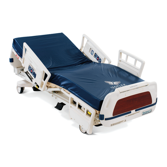
Page 7: Bed Illustration
PATIENT’S LEFT I.V. and Fracture Frame Mount Footboard Control Steer Panel Pedal Siderail Release Handle Brake Pedal Foley Bag Hooks FOOT END (Standard) I.V. and Fracture Frame Mount (Behind Foot Board) Return To Table of Contents www.stryker.com 3002-409-001 REV A... -
Page 8: Symbols
Refer to your local distributor for return and/or collection systems available in your country. Return To Table of Contents 3002-409-001 REV A www.stryker.com... -
Page 9: Safety Tips And Guidelines
Use only a Stryker supplied interface cable. Use of any other cable may cause the bed to function improperly which may result in patient or user injury. - Page 10 When attaching equipment to the frame, ensure it will not impede normal operation. For example: hooks on hanging equipment must not actuate control buttons, equipment must not hide the nurse call button, etc.. Return To Table of Contents 3002-409-001 REV A www.stryker.com...
-
Page 11: Zoom Option
Zoom option. WarNINg • The 3002 Patient Transport Frame is intended for use by trained hospital personnel only. Failure to properly train personnel could result in injury. • USE CAUTION while maneuvering the unit with the drive wheel activated. Always ensure there are no obstacles near the unit while the drive wheel is activated. -
Page 12: Ibed Awareness Option
Awareness as the display information to troubleshoot the bed will get lost. • If the optional iBED Awareness system is being used; use of accessories that cover the alert light are not recommended. Return To Table of Contents 3002-409-001 REV A www.stryker.com... -
Page 13: Setup Procedures
”Patient Station”, ”Head Wall”, ”Docker Station”, or equivalent (whichever applies). Test the interface cable to verify it is functioning properly. WarNINg Use only a Stryker supplied interface cable. Use of any other cable may cause the bed to function improperly which may result in patient or user injury. •... -
Page 14: Zoom Option
Run through the operation of the drive wheel (see page 35) to ensure it is operating properly. If any problems are found during bed setup, contact Stryker Customer Service at (800) 327−0770. Return To Table of Contents 3002-409-001 REV A... -
Page 15: Base Operation Guide
Attempting to move the bed laterally when the steer pedal is activated may cause injury to the user. Return To Table of Contents www.stryker.com 3002-409-001 REV A... -
Page 16: Litter Operation Guide
Clean Velcro AFTER EACH USE. Saturate Velcro with disinfectant and allow disinfectant to evaporate. (Appropriate disinfectant for nylon Velcro should be determined by the hospital.) Return To Table of Contents 3002-409-001 REV A www.stryker.com... -
Page 17: Night Light Usage
If the CPR board option was not purchased, the head board can also be removed and used as an emergency CPR board. Return To Table of Contents www.stryker.com 3002-409-001 REV A... -
Page 18: Operating I.v. Poles
(B) of the pole and raise it to the desired height. Turn knob (A) clockwise to tighten the telescoping portion in place. CaUTION The weight of the I.V. bags should not exceed 40 pounds. Return To Table of Contents 3002-409-001 REV A www.stryker.com... -
Page 19: Positioning Siderails
The purpose of the red nurse call light on the siderails is to ensure the patient immediately knows which button to push to contact the nurse station. Turning the red light off may compromise this ability, especially in a darkened room. Return To Table of Contents www.stryker.com 3002-409-001 REV A... -
Page 20: Inside Siderail Function Guide
Push to mute TV volume. Push again to turn the sound This panel is optional equipment. back on. Push to display the closed captioning. Push again turn closed captioning. This panel is optional equipment. Return To Table of Contents 3002-409-001 REV A www.stryker.com... -
Page 21: Outside Siderail Function Guide
(foot end down). For Short Beds it will tiltl approximatley −10 Release the button to stop bed movement; hold the button until movement stops to complete the function. This panel is optional equipment. Return To Table of Contents www.stryker.com 3002-409-001 REV A... -
Page 22: Footboard Operation Guide
Push to raise Fowler. Push to raise Knee Gatch. Push to lower Fowler. Push to lower Knee Gatch. • This panel is optional equipment. Return To Table of Contents 3002-409-001 REV A www.stryker.com... -
Page 23: Led Display Panel Guide
The lockout buttons on the foot board lock the Fowler, Gatch and Bed Up/Down functions and prevent motion of the bed. It is the responsibility of attending medical personnel to determine whether these functions should be locked and to use the buttons accordingly. Return To Table of Contents www.stryker.com 3002-409-001 REV A... -
Page 24: Chaperone Bed Exit (Optional Equipment)
XPRT, do not initialize (“arm”) bed exit with Percussion, Vibration, Rotation or Turn Assist active. The patient motion and position resulting from a dynamic therapy mattress may adversely affect bed exit system performance. Return To Table of Contents 3002-409-001 REV A www.stryker.com... -
Page 25: Chaperone Bed Exit With Zone Control (Optional Equipment)
XPRT, do not initialize (“arm”) bed exit with Percussion, Vibration, Rotation or Turn Assist active. The patient motion and position resulting from a dynamic therapy mattress may adversely affect bed exit system performance. Return To Table of Contents www.stryker.com 3002-409-001 REV A... -
Page 26: Chaperone Zone Settings
If the patient’s center of gravity moves from the original location more than 1 inch to either side or 1 inch toward the head or foot, an alarm will sound. NOTE All zone dimensions are ± .5 inches. Return To Table of Contents 3002-409-001 REV A www.stryker.com... -
Page 27: Scale System Operation Guide
Do not zero bed scales or weigh patient with Percussion, Vibration, Rotation or Turn Assist active. Patient motion and position resulting from the dynamic therapy mattress may adversely affect scale system performance. Return To Table of Contents www.stryker.com 3002-409-001 REV A... - Page 28 30 5. Displaying the Weight Log - page 31 6. Viewing Patient Weight In Gain/Loss Mode - page 32 7. Changing the Numerical Value Of Displayed Weight - page 33 Return To Table of Contents 3002-409-001 REV A www.stryker.com...
-
Page 29: Preparing The Bed For Patient Stay / Zeroing The Scale System
Unplug the bed power cord from the wall socket and plug it back in. If the problem continues, call a service technician. activating The Scale System and Displaying Patient Weight • Press and release The scale monitor will read: “LET GO FOR SCALE” “WEIGHING” “XXX.X LB” Return To Table of Contents www.stryker.com 3002-409-001 REV A... -
Page 30: Adding Or Removing Items During A Patient's Stay
”XXX.X LB” • If the unit of measurement has been locked, the display will read: “UNITS ARE LOCKED” Note A service technician must be called to unlock the unit of measurement. Return To Table of Contents 3002-409-001 REV A www.stryker.com... -
Page 31: Displaying The Weight Log
The first weight reading displayed (1.) is the most recent. If the change in the patient’s weight since the last reading was taken is less than .2 pounds, the log will not update. Zeroing the scale system clears the weight log. Return To Table of Contents www.stryker.com 3002-409-001 REV A... -
Page 32: Viewing Patient Weight In Gain / Loss Mode
Menu Mode. The scale monitor will read: “ FOR OPTIONS” • Press to scroll through the menu options. The scale monitor will read: “QUIT GAIN/LOSS” “PUSH ENTER” • Press The scale monitor will read: “XXX.X LB“ Return To Table of Contents 3002-409-001 REV A www.stryker.com... -
Page 33: Changing The Numerical Value Of Displayed Weight
The scale monitor will read: “XXX.X LB” NOTE If one of the load cells is malfunctioning or overloaded, the scale monitor will read: “Scale Sys. Error” “Call for service” Call a service technician. Return To Table of Contents www.stryker.com 3002-409-001 REV A... -
Page 34: Optional Pendant Operation Guide
Press to turn on the volume of reading lights. the TV/Radio. Press to raise Press to raise head section. knee section. Press to lower Press to lower knee section. head section. Return To Table of Contents 3002-409-001 REV A www.stryker.com... -
Page 35: Zoom™ Option Operation Guide
Use caution when transporting the unit down halls, through doors, in and out of elevators, etc. Damage to the siderails or other parts of the unit could occur if the unit comes in contact with walls or door frames. Return To Table of Contents www.stryker.com 3002-409-001 REV A... - Page 36 When attaching equipment to the frame, ensure it will not impede normal operation. For example: hooks on hanging equipment must not actuate control buttons, equipment must not hide the nurse call button, etc. Return To Table of Contents 3002-409-001 REV A www.stryker.com...
-
Page 37: Head End Control Panel Operation
The “Plug Bed In To Charge” LED will be illuminated while the battery power switch is on if the battery level is low. Plug the bed power cord into the wall socket to charge the batteries. Return To Table of Contents www.stryker.com 3002-409-001 REV A... -
Page 38: Battery Charging And Operation
Bed Exit, Scale and Motion will cease to operate when the unit enters the power save mode. Injury to the patient could occur if proper patient monitoring protocol is not observed. Return To Table of Contents 3002-409-001 REV A www.stryker.com... -
Page 39: Optional Ibed Awareness Operation Guide
Patient Gatch Lock Gatch Up iBED On/Off Patient Bed Up/ Gatch Down Menu Down Lock Trend Cardiac Chair Menu Up Reverse Trend CPR Drop Menu Down Exit Bed Up Bed Exit Arm/Disarm Enter Return To Table of Contents www.stryker.com 3002-409-001 REV A... -
Page 40: Footboard Control Panel Functions
Cardiac Chair approximately 52 degrees and the bed will tilt to approximately -12 Reverse Trendelenburg (foot end down). Activates electronic CPR function; flattens litter and puts bed in low CPR Drop height. Return To Table of Contents 3002-409-001 REV A www.stryker.com... - Page 41 Cancel operations. Enter Selects menu item; also used to Save and/or Cancel operations. Note iBED Awareness options populated with Chaperone Bed Exit features without Zone Control will not have button 17. Return To Table of Contents www.stryker.com 3002-409-001 REV A...
-
Page 42: Led Indicators: Footboard
Zone 3 LED: LED is illuminated when Bed Exit is “On” and Zone 3 activated. aMBEr Note iBED Awareness options populated with Chaperone Bed Exit features without Zone Control will not have items M or N. Return To Table of Contents 3002-409-001 REV A www.stryker.com... -
Page 43: Led Indicators: Dashboard
Siderail LED: LED is illuminated if iBED Awareness system is “On”. The LED aMBEr will blink when siderail state has changed. Power LED: LED is illuminated when bed has power. grEEN Return To Table of Contents www.stryker.com 3002-409-001 REV A... -
Page 44: Display Screens
If this screen is inactive for 60 seconds, the Backlighting will be reduced. • Figure 2 shows an example of the “Status” Screen: Figure 2 Message Screen • As required message screens are provided during alarm conditions and user interaction with the bed. Return To Table of Contents 3002-409-001 REV A www.stryker.com... -
Page 45: Main Menu Screen
• NOTE: Refer to Figure 6 • If the Gain or the Loss exceeds 99.9 lb, then the system will display ‘---’ instead of a value. Figure 6 Return To Table of Contents www.stryker.com 3002-409-001 REV A... - Page 46 - Press “Exit/X” to cancel operation. • If “Enter/ ” is pressed, the message “Do Not Touch Bed” will flash on the display. • If “Exit/X” is pressed, “Patient Weight Changed” message will display. Return To Table of Contents 3002-409-001 REV A www.stryker.com...
- Page 47 Scroll through the 10 Tone Patterns listed in the menu. A sample alarm will sound for each Tone Pattern highlighted. • Select desired Tone Pattern and Press “Enter/ ” • “Save Successful” message will be displayed. Return To Table of Contents www.stryker.com 3002-409-001 REV A...
- Page 48 Select “On” to Enable or “Off” to disable and then press “Enter/ ” • “Save Successful” message will be displayed. 8. Exit Menu Exits Main Menu screen and returns display to the default Status Screen. Return To Table of Contents 3002-409-001 REV A www.stryker.com...
-
Page 49: Ibed Awareness Functionality
The following message will be displayed on the screen: “Bed Status On”. Turning off the iBED awareness system Press and hold the iBED On/Off button. The following message will be displayed on the screen: “Bed Status Off”. Return To Table of Contents www.stryker.com 3002-409-001 REV A... -
Page 50: Ibed Awareness Monitoring And Alarms
The siderail LED on the dashboard blinks and the display screen flashes between Figure 17 message and Figure 18 message. Figure 18 Figure 17 Note The arrow pointing to the siderail in Figure 17 and 18 will change depending on the siderail position in alarm. Return To Table of Contents 3002-409-001 REV A www.stryker.com... -
Page 51: Bed Exit
If bed is put in CPR position manually or by pressing the CPR button, Figure 24 will be displayed. Figure 21 Figure 22 Lock Violation, Turn Off Lock or Raise Fowler Figure 23 Figure 24 Return To Table of Contents www.stryker.com 3002-409-002 REV B... -
Page 52: Bed Motion Lock
If the Patient Control lock button is pressed Figure 25 as shown above will be displayed. • If the Patient Control lock button is pressed when already “on” then Figure 26 as shown above will be displayed. Return To Table of Contents 3002-409-001 REV A www.stryker.com... -
Page 53: Cleaning
SOME CLEANING PRODUCTS ARE CORROSIVE IN NATURE AND MAY CAUSE DAMAGE TO THE PRODUCT IF USED IMPROPERLY. If the products described above are used to clean Stryker patient care equipment, measures must be taken to insure the beds are wiped with a damp cloth soaked in clean water and thoroughly dried following cleaning. -
Page 54: Preventative Maintenance
_____ iBED Awareness Side Indicator LEDs working properly (iBED Awareness option). _____ Inspect footboard control labeling for signs of degradation (iBED Awareness option). Bed Serial Number: Completed by: _______________________________________ Date: ___________________ Return To Table of Contents 3002-409-001 REV A www.stryker.com... -
Page 55: Warranty
Stryker Medical Division, a division of Stryker Corporation, warrants to the original purchaser the Secure II Med-Surg Bed to be free from defects in material and workmanship for a period of one (1) years after date of delivery. Stryker’s obligation under this warranty is expressly limited to supplying replacement parts and labor for, or replacing, at its option, any product which is, in the sole discretion of Stryker, found to be defective. -
Page 56: Service Contract Programs
Stryker authorized parts used Service during regular business hours (8−5) * Does not include maintenance due to abuse or for any disposable items. Stryker reserves the right to change options without notice. Stryker Medical also offers personalized service contracts. Pricing is determined by age, location, model and condition of product. - Page 58 3800 E. Centre Ave., Portage, Michigan USA 49002 CANADA Stryker Canada 45 Innovation Drive Hamilton, Ontario Canada L9H 7L8 European representative Stryker France ZAC Satolas Green Pusignan Av. De Satolas Green 69881 MEYZIEU Cedex France 2007/11 3002-409-001 REV A www.stryker.com...
Need help?
Do you have a question about the 3002 and is the answer not in the manual?
Questions and answers
Can an S3 Stryker bed be connected to a 37 pin Hillrom nurse call wall jack? What is the part number for such a cable?
Yes, the Stryker 3002 S3 bed can be connected to a 37-pin Hillrom nurse call wall jack. The required cable must be a Stryker-supplied interface cable. The part number for the correct interface cable is not provided in the context.
This answer is automatically generated