Table of Contents
Advertisement
Advertisement
Table of Contents

Subscribe to Our Youtube Channel
Related Manuals for Pfeiffer Vacuum UNO 2.5


Summary of Contents for Pfeiffer Vacuum UNO 2.5
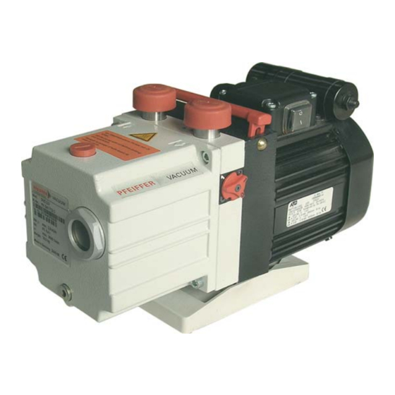
- Page 1 UNO/DUO 2.5, DUO 2.5 C, UNO 5 Rotary Vane Pump Operating Instructions...
-
Page 2: Table Of Contents
Table of contents Table of contents About this manual ..........3 1.1 Validity. -
Page 3: About This Manual
1 About this manual 1.1 Validity This operating manual is for customers of Pfeiffer Vacuum. It describes the functioning of the designated product and provides the most important information for safe use of the unit. The description follows applicable EU guidelines. All information provided in this operating manual refer to the current state of the product's development. - Page 4 About this manual Pictograph Prohibition of an action or activity in connection with a source of danger, definitions the disregarding of which may result in serious accidents Warning of a displayed source of danger in connection with operation of the unit or equipment Command to perform an action or task associated with a source of dan- ger, the disregarding of which may result in serious accidents Important information about the product or this document...
-
Page 5: Safety
Installation and operation of accessories Pfeiffer Vacuum pumps can be equipped with a series of adapted accessories. The in- stallation, operation and maintenance of connected devices are described in detail in the operating instructions of the individual components. -
Page 6: Transport And Storage
Transport and storage ● connection to pumps or units which are not suitable for this purpose according to their operating instructions ● connection to units which have exposed voltage-carrying parts 3 Transport and storage 3.1 Transport Transport instructions Remove the locking cap from the vacuum and exhaust flange immediately before con- necting! –... -
Page 7: Product Description
Product description 4 Product description 4.1 Product identification To correctly identify the product when communicating with Pfeiffer Vacuum, always have the information from the rating plate available. ● Pump model and model number ● Type and amount of operating fluid ●... -
Page 8: Function
Installation 4.2 Function Vacuum pumps of the UNO/DUO series are oil-sealed, single-/two-stage rotary vane vacuum pumps. The vacuum pumps are equipped with a high vacuum safety valve that vacuum seals the vacuum chamber and vents the pump at the same time when the pump is at standstill. -
Page 9: Filling Up The Operating Fluid
NOTICE Use approved operating fluids only! The use of operating fluids that have not been approved by Pfeiffer Vacuum shall result in a limited warranty. In such cases, it is not possible to guarantee that product-specific performance data will be achieved. -
Page 10: Connecting The Vacuum Side
Installation WARNING Toxic vapours! Danger of poisoning when igniting and heating synthetic operating fluids (e.g. F4/F5) above 300°C. Observe the application instructions. Do not allow operating fluid to make contact with tobacco products; observe safety precautions when handling chemicals. 5.3 Connecting the vacuum side ... -
Page 11: Connecting To The Mains Power Supply
Installation Lay piping from the pump sloping downward so that no condensate can flow back into the pump; otherwise fit a condensate separator. – If an air trap is created in the system, then a device for draining condensation water must be provided at the lowest point. - Page 12 Installation Changing the voltage range Only valid for pumps with reversible motor: The mains voltage must be determined on-site each time before the pump is installed or moved to a different location. Disconnect the pump from the power supply. ...
-
Page 13: Operation
Operation 6 Operation 6.1 Before switching on the pump Check the operating fluid level in the sight glass. Compare the voltage and frequency information on the rating plate with the mains volt- age and frequency values. Check that the exhaust connection allows free flow (max. permissible pressure 150 kPa absolute). - Page 14 Operation If the pumping process requires the connection of flushing gas, the C version of the gas Gas ballast valve, ballast valve with the flushing gas connection must be used. corrosive gas version O-ring O-ring Proportioning screw Flushing gas connection (for DN 6 mm hose) Fig.
- Page 15 Operation Fig. 9: Assembling the solenoid valve at the gas ballast inlet Performance data of the solenoid valve 2/2 way valve closed when disconnected Supply voltage 24 VDC, +/- 10 % Power input Socket Type 2506 Threaded connection of flushing 1/8"...
-
Page 16: Switching Off The Pump
Maintenance 6.4 Switching off the pump The pump can be switched off in any pressure range. Rotary vane pumps have an integrated safety valve on the intake side. If the differential pressure between the exhaust side and the intake side is ≥ 250 hPa, then the valve clos- es automatically and vents the pump when the pump is switched off. - Page 17 Certain repair and overhaul work should only be performed by Pfeiffer Vacuum Service Checklist for inspec- (PV). Pfeiffer Vacuum will be released from all warranty and liability claims if the required tion, maintenance intervals for inspection, maintenance, or overhaul are exceeded or inspection, mainte- and overhaul nance, repair or overhaul procedures are not performed properly.
-
Page 18: Changing The Operating Fluid
Depending on the applications, Pfeiffer Vacuum recommends determining the ex- act service life of the operating fluid during the first year of operation. The replacement interval may vary from the guide value specified by Pfeiffer Vacuum depending on the thermal and chemical loads, and the accumulation of suspended par- ticles and condensation in the operating fluid. - Page 19 Fill up with operating fluid and check the filling level (see p. 9, chap. 5.2). Request safety data sheets for operating fluids and lubricants from Pfeiffer Vacuum or download them from the Internet. Dispose of operating fluid according to the local regulations.
-
Page 20: Decommissioning
Replace the radial shaft sealing rings and further elastomer parts. Replace bearings at pumps with anti-friction bearings. Follow the maintenance instructions and inform Pfeiffer Vacuum. 8.3 Disposal Products or parts thereof (mechanical and electrical components, operating fluids, etc.) may cause environmental burden. -
Page 21: Malfunctions
Thermal protection switch has re- Detect and fix cause of overheating; allow sponded pump to cool off if necessary. Pump system dirty Clean pump; contact Pfeiffer Vacuum Ser- vice if necessary. Pump system damaged Clean and overhaul pump; contact Pfeiffer Vacuum Service if necessary. - Page 22 NOTICE Service work should be carried out by qualified personal only! Pfeiffer Vacuum is not liable for any damage to the pump resulting from work carried out improperly. Take advantage of our service training programs; additional information at www.pfeif- fer-vacuum.com.
-
Page 23: Service
The following steps are necessary to ensure a fast, smooth servicing process: Download the forms "Service Request" and "Declaration on Contamination". Fill out the "Service Request" form and send it by fax or e-mail to your Pfeiffer Vacuum service address. -
Page 24: Spare Parts
PK D31 707 ... UNO 2.5 PK E00 002 -T PK E08 003 -T PK E01 004 -T PK E02 005 -T PK E04 001 -T PK E05 001 -T PK E06 001 -T PK D31 712 PK D41 707 ... - Page 25 Spare parts Spare parts pack- Parts according to the exploded view on the following page Set of seals PK E00 002 -T 13.1, 14 , 58, 100, 101, 102, 103, 104, 105, 106, 107, 108, 109*, 110. Set of vanes PK E08 003 -T 12.4, 12.10, 12.15 PK E08 004 -T...
- Page 26 Spare parts Intake connection Exhaust connection Coupling half Valve plate Cone strainer Motor Gas ballast valve O-ring (Fig. see Chap. 6.3) O-ring (Fig. see Chap. 6.3) Valve flap/gas ballast valve Support stand Casing 1/108 Handle 2/108 Pump system (UNO) Pump system (DUO) 12.4 Vane 12.10 Hydraulic vane 102/...
-
Page 27: Accessories
Accessories 12 Accessories Designation UNO 2.5 DUO 2.5 KAS 16, condensate separator for pumping speeds from 1.25 to 5 m /h PK Z10 003 PK Z10 003 ONF 16, oil mist filter for pumping speeds of up to 1.25-5 m... -
Page 28: Technical Data
Technical data 13 Technical data Parameter UNO 2.5 UNO 5 Flange (in) DN 16 ISO-KF DN 16 ISO-KF Flange (out) DN 16 ISO-KF DN 16 ISO-KF Pumping speed at 50 Hz 2.5 m 4.6 m Pumping speed at 60 Hz 2.9 m... -
Page 29: Dimensions
Technical data 13.1 Dimensions DN 16 ISO-KF 31.5 (8.5) 32.5 ± 1 ± 1 Fig. 12: Motor versions: 95 ... 105 V, 50 Hz / 100 ... 115 V, 60 Hz DN 16 ISO-KF 31.5 (8.5) 32.5 ± 1 Fig. 13: Motor versions: 190 ... 210 V, 50 Hz / 200 ... 220 V, 60 Hz; 220 ... 240 V, 50/60 Hz... - Page 30 Technical data DN 16 ISO-KF 31.5 (8.5) 32.5 ± 1 ± 1 Fig. 14: Motor version: 115/230, 50/60 Hz DN 16 ISO-KF 31.5 (8.5) 32.5 ± 1 ± 1 Fig. 15: Motor versions: 100 ... 105 V, 50 Hz / 110 ... 130 V, 60 Hz...
-
Page 31: Declaration Of Conformity
In addition, the product cited below satisfies all relevant provisions of EC directive "Elec- tromagnetic Compatibility" 2004/108/EC . The agent responsible for compiling the technical documentation is Mr. Sebastian Ober- beck, Pfeiffer Vacuum GmbH, Berliner Straße 43, 35614 Aßlar. ® /DuoLine™... - Page 32 Pfeiffer Vacuum stands for innovative and custom Leading. Dependable. Customer Friendly vacuum solutions worldwide. For German engineering art, competent advice and reliable services. Ever since the invention of the turbopump, we´ve been setting standards in our industry. And this claim to leadership will continue to drive us in the future.
Need help?
Do you have a question about the UNO 2.5 and is the answer not in the manual?
Questions and answers