
Related Manuals for Pfeiffer Vacuum UnoLine UNO 35


Summary of Contents for Pfeiffer Vacuum UnoLine UNO 35
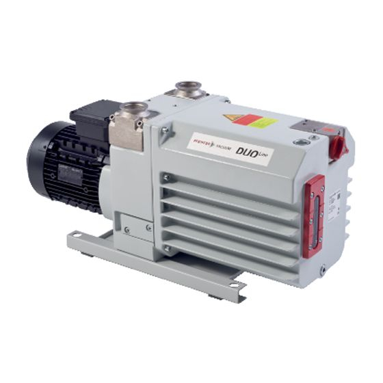
- Page 1 Betriebsanleitung • Operating Instructions Translation of the Original Operating Instructions UnoLine™ DuoLine™ Rotary Vane Pumps UNO/DUO 35/65 UNO/DUO 35/65 M DUO 35/65 C/MC...
-
Page 2: Table Of Contents
Table of contents Table of contents About this manual........3 Validity. -
Page 3: About This Manual
1 About this manual 1.1 Validity This operating manual is for customers of Pfeiffer Vacuum. It describes the func- tioning of the designated product and provides the most important information for safe use of the unit. The description follows applicable EU guidelines. All informa- tion provided in this operating manual refer to the current state of the product's de- velopment. - Page 4 About this manual Pictograph Prohibition of an action or activity in connection with a definitions source of danger, the disregarding of which may result in serious accidents. Warning of a displayed source of danger in connection with operation of the unit or equipment. Command to perform an action or task associated with a source of danger, the disregarding of which may result in serious accidents.
-
Page 5: Safety
• The vacuum pump may only be used to generate a vacuum. • Installation, operating and maintenance regulations must be complied with. • Using accessories not mentioned in this manual is not permitted without autho- risation from Pfeiffer Vacuum. -
Page 6: Improper Use
• Use of the vacuum pump to generate pressure. • Pumping of liquids. • The use of operating fluids not specified by Pfeiffer Vacuum. • Connection to pumps or units which are not suitable for this purpose according to their operating instructions. -
Page 7: Product Description
4 Product description 4.1 Product identification To ensure reliable identification of the product, always keep all of the information on the rating plate to hand, and use it when communicating with Pfeiffer Vacuum: • Pump model and model number • Serial number •... -
Page 8: Construction And Function
Product description 4.2 Construction and function The UnoLine™/DuoLine™ pumps are oil sealed, single-/two-stage rotary vane pumps with air cooling and pressure oil lubrication and suitable for many coarse and fine vacuum applications. The pumps are equipped with a vacuum safety valve that vacuum seals the vacuum chamber and vents the pump at the same time when the pump is at a standstill. -
Page 9: Installation
Installation 5 Installation 5.1 Setting up the pump Installation location Observe the following requirements when setting up the pump: • Note the load-bearing capacity of the mounting surface. • Maximum installation altitude 2000 m (above mean sea level) • Permissible ambient temperature: +12 ... +40°C •... -
Page 10: Connecting The Exhaust Side
Installation 5.3 Connecting the exhaust side CAUTION High pressure in the exhaust line! Danger of damage to the seals and danger of the pump bursting. Install the line without shut-off valves on the exhaust side. If there is danger of a build-up of excess pressure (> 1500 mbar abs.) in the lines, observe all official accident prevention safety regulations. - Page 11 Installation NOTE The transmission power of the pump’s magnetic coupling is so great that there is no overload protection for the motor. Three phase motor Inspection of the direction of rotation With pumps with three-phase motors is it necessary to check the direction of rota- tion! CAUTION Operating fluids may leak out!
- Page 12 Installation On site fuse protection with current circuit-breaker valid for motor version Depending on the process conditions and the intake pressure, the motor can be- without switch/with 3PTC come overloaded, i.e. the power input can exceed I . In cyclical operation, it is per- missible for the current to temporarily exceed the rated current I by 15%, provided that the motor temperature is monitored by means of a thermistor.
-
Page 13: Filling Up The Operating Fluid
Pumps for special applications (e.g. for pumping corrosive gases) can be operated with other operating fluids. These must be defined in accordance with Pfeiffer Vacuum specifications before initial assembly and ordered separately. Permissible operating fluids • P3 (Standard operating fluid) •... -
Page 14: Operations Monitoring (Option)
Installation 5.6 Operations monitoring (option) A pressure switch can be installed on the side of the support to monitor the oil pressure of the rotary vane pump during operations. By pressure drop and when the pump is at rest, the contact of the pressure switch opens. The signal can be used to control external valves: Switching voltage: 5 ... -
Page 15: Operation
Operation 6 Operation 6.1 Before switching on the pump Check the operating fluid level in the sightglass. Compare the voltage and frequency information on the rating plate with the mains voltage and frequency values. Check that the exhaust connection allows free flow (max. permissible pressure 1.5 bar absolute). - Page 16 Connect flushing gas at the hose nozzle of the gas ballast valve. Set flushing gas pressure; maximum pressure 1.5 bar (absolute). – Select the type and amount of flushing gas depending on the process; consult Pfeiffer Vacuum if necessary. CAUTION Flushing gas pressure higher than allowed endangers the operational reliability of the pump.
-
Page 17: Switching Off The Pump
Operation 6.4 Switching off the pump The pump can be switched off in any pressure range. Rotary vane pumps have an integrated safety valve on the intake side. If the differ- ential pressure between the exhaust side and the intake side is ≥ 250 mbar, then the valve closes automatically and vents the pump when the pump is switched off. -
Page 18: Maintenance
Maintenance 7 Maintenance 7.1 Precautions WARNING Danger of injury from moving parts! After power failure or motor shutdown due to overheating, the motor may restart auto- matically. Secure the motor so that it cannot be switched on while any work is being performed on the pump. -
Page 19: Changing The Operating Fluid
Checklist for inspection, Certain repair and overhaul work should only be performed by Pfeiffer Vacuum Service (PV). Pfeiffer Vacuum will be released from all warranty and liability claims maintenance and over- if the required intervals for inspection, maintenance, or overhaul are exceeded or... - Page 20 Fill up with operating fluid and check the filling level (see p. 13, chap. 5.5). NOTE Request safety data sheets for operating fluids and lubricants from Pfeiffer Vacuum or download them from the Internet. Dispose of operating fluid according to the local regulations.
-
Page 21: Cleaning The Gas Ballast Valve
Maintenance 7.3 Cleaning the gas ballast valve Gas ballast valve only becomes dirty if dusty ambient air issucked in. Unscrew screw 74.4 (standard version). Remove gas ballast head 74.5. Be careful with O-rings 74.14 and 74.18 (standard version). Unscrew two screws 74.22 (74.23 C version). Remove gas ballast flange 74.2 (74.7 C version);... - Page 22 Maintenance 74.1 Gas ballast valve housing 74.9 74.3 Silencer screw 74.16 74.7 Special gas ballast flange 74.8 Spindle 74.20 74.9 Hose connecting piece 74.7 184 74.18 74.3 74.12 74.10O-ring 74.12O-ring 74.16O-ring 74.18O-ring 74.20O-ring 74.24Screw 74.34 74.34Circlip 74.8 184 Screw 232 O-ring 238 O-ring 74.24 74.12 74.10 74.32...
-
Page 23: Cleaning And Setting The Silencer
Maintenance 7.4 Cleaning and setting the silencer The silencer is a nozzle set inside the gas ballast flange which silences the knocking sound of the oil. When dirty it should be cleaned or replaced. Cleaning the silencer Unscrew silencer screw 74.3; be careful with O-ring 74.12. Clean the boring. -
Page 24: Decommissioning
Pfeiffer Vacuum Service. Depending on how long the pump is taken out of operation, it may be necessary to replace the radial shaft sealing rings. -
Page 25: Malfunctions
Malfunctions 9 Malfunctions Please note the following instructions should the pump malfunction: DANGER Strong magnetic field in the vicinity of the drive system! Danger to life for persons with cardiac pacemakers when the drive system is disas- sembled. Persons with cardiac pacemakers must not enter the area of the magnetic field. Disassembled magnetic couplings must be kept away from computers, data storage media and other electronic components. -
Page 26: Troubleshooting
Service if necessary NOTE Service work should only be carried out by qualified personal! Pfeiffer Vacuum is not liable for any damage to the pump resulting from work carried out improperly. Take advantage of our service training programs from technical training; additional information at www.pfeiffer-vacuum.net. -
Page 27: Service
Returning contaminated vacuum pumps Units which are microbiologically, explosively or radioactively contaminated will not be accepted by Pfeiffer Vacuum as a matter of principle. Hazardous substances are substances and compounds in accordance with the hazardous goods directive (current version). Should pumps be contaminated or the contamination declara- tion be missing, Pfeiffer Vacuum will decontaminate the pumps at your cost. -
Page 28: Spare Parts
Spare parts 11 Spare parts Please also specify model number of the the rating plate when ordering accesso- ries or spare parts. Set of seals The set of seals contains all seals including all o-rings of the assembly groups and the subassemblies. -
Page 29: Spare Parts Packages
Please state all information on the rating plate when ordering spare parts. Other spare parts than those described in this manual must not be used without the agreement of Pfeiffer vacuum. UNO 35 PK E20 001 -T PK E21 001 -T PK E22 001 -T... -
Page 30: Accessories
Accessories 12 Accessories Further detailed accessories are contained in the Pfeiffer Vacuum printed Cata- logue or the Online Catalogue. Description Size Number Comments/ (relevant manual) C version (for Gas ballast valve, retrovit kit PK 223 713 -U flushing gas connection) -
Page 31: Technical Data
Technical Data 13 Technical Data UNO/DUO 35 Feature UNO 35 DUO 35 Flange (in) DN 40 ISO-KF DN 40 ISO-KF Flange (out) DN 40 ISO-KF DN 40 ISO-KF Pumping speed at 50 Hz 32 m 32 m Pumping speed at 60 Hz 36 m 36 m ≤... -
Page 32: Dimension Diagram
Technical Data 13.1 Dimension diagram 644 (724) 311 (391) DN 40 ISO-KF 65 (145) ∅ ( ... ) --> UNO/DUO 65 Fig. 16: UNO/DUO 35/65 (775.5 ) 311 (391) DN 40 ISO-KF 65 (145) ∅ (...) --> DUO 65 M Fig. - Page 33 In addition, the product cited below satisfies all relevant provisions of EC directive "Electromagnetic Compatibility" 2004/108/EC . The agent responsible for compiling the technical documentation is Mr. Sebastian Oberbeck, Pfeiffer Vacuum GmbH, Berliner Straße 43, 35614 Aßlar. ® DuoLine /DuoLine™...
- Page 34 Roots pumps Dry compressing pumps Leak detectors Valves Components and feedthroughs Vacuum measurement Gas analysis System engineering Service Pfeiffer Vacuum Technology AG · Headquarters/Germany Tel. +49-(0) 64 41-8 02-0 · Fax +49-(0) 64 41-8 02-2 02 · info@pfeiffer-vacuum.de · www.pfeiffer-vacuum.net...
Need help?
Do you have a question about the UnoLine UNO 35 and is the answer not in the manual?
Questions and answers