
Related Manuals for Pfeiffer Vacuum UnoLine UNO 200


Summary of Contents for Pfeiffer Vacuum UnoLine UNO 200
- Page 1 Betriebsanleitung • Operating Instructions UnoLine™ Rotary Vane Pumps UNO 200 UNO 240 UNO 400 UNO 630...
-
Page 2: Table Of Contents
Table of contents Table of contents About this manual........3 Validity. -
Page 3: About This Manual
1 About this manual 1.1 Validity This operating manual is for customers of Pfeiffer Vacuum. It describes the func- tioning of the designated product and provides the most important information for safe use of the unit. The description follows applicable EU guidelines. All informa- tion provided in this operating manual refer to the current state of the product's de- velopment. - Page 4 About this manual Piktograph Prohibition of an action or activity in connection with a definitions source of danger, the disregarding of which may result in serious accidents. Warning of a displayed source of danger in connection with operation of the unit or equipment. Command to perform an action or task associated with a source of danger, the disregarding of which may result in serious accidents.
-
Page 5: Safety
• Use of the vacuum pump to generate pressure. • Pumping of liquids. • The use of operating fluids not specified by Pfeiffer Vacuum. • Connection to pumps or units which are not suitable for this purpose according to their operating instructions. -
Page 6: Transport And Storage
Transport and storage 3 Transport and storage 3.1 Transport Transport instructions Remove the locking cap from the vacuum flange immediately before connec- ting! – Check the protective strainer, paying attention to the o-ring. Use only the crane eye sideways at the operating fluid separator to lift the pump. Fig. -
Page 7: Product Description
Product description 4 Product description 4.1 Product identification To correctly identify the product when communicating with Pfeiffer Vacuum, al- ways have the information from the rating plate available and use it: • Pump model and model number • Serial number •... -
Page 8: Function
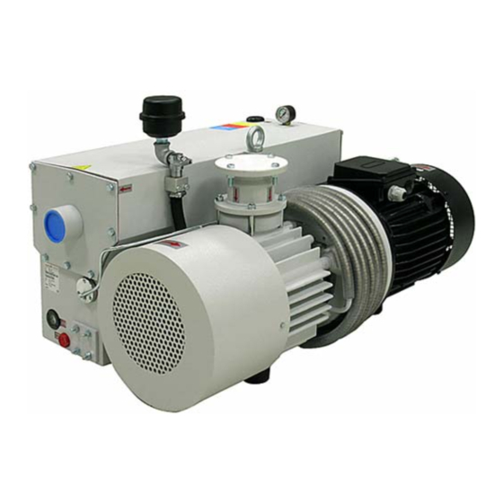
Product description 4.2 Function The UnoLine™ series pumps are oil-sealed, single stage operating rotary vane pumps with air cooling and circulatory lubrication. A vacuum safety valve in the intake flange closes the intake line automatically and prevents operating fluid back- streaming when the pump is switched off. -
Page 9: Installation
Installation Vacuum flange 75 74.4 140 74 8 Exhaust flange Pump casing Gas ballast valve 74.4 Gas ballast filter 75 Operating fluid separator 80 Sight glass 140 Operating fluid filler screw 250 Motor 280 Operating fluid cooler 290 Operating fluid return unit 80 280 290 6... -
Page 10: Connecting The Vacuum Side
Installation When installing the pump in a closed housing, ensure there is sufficient air cir- culation. – Sightglass and gas ballast valve must be visible and readily accessible. – Voltage and frequency information given on the motor rating plate must be visible. -
Page 11: Connecting To The Mains Power Supply
Installation 5.4 Connecting to the mains power supply Depending on the pump type, different motor versions are possible: • Three phase motor (without switch and mains cable). DANGER Voltage-bearing elements Electrical hazard when using electricity. The electrical connection can be carried out only by trained and authorised electricians. - Page 12 Installation Tripping devices store the shutdown event and need to be manually switched back on again via the integrated RESET button or via the external RESET S3. Mains-ON is detected as an automatic RESET. Other approved motor temperature monitoring can be used also by the operator. Set up the connections so that the directional rotation indicated on the pump is maintained, regardless of the representations in the current flow diagram.
- Page 13 Installation 400V 68...80˚C Fig. 8: 3 phases 400 V/N/PE The Three Phase Current Motor Circuit Delta Connection The three coils are connected in series with the connection point connected to the mains. The voltage of each coil is the same as the mains voltage whereas the mains current is the cube root of the coil current.
-
Page 14: Filling Up The Operating Fluid
The delivery consignment for the standard pump contains suffient operating flu- id for one filling. The use of other operating fluids requires prior authorisation from Pfeiffer Vacuum. Permissible operating fluid • D1 (standard operating fluid) •... -
Page 15: Install Cooling Water Unit With Thermal Circuit Breaker (Option)
Installation 5.6 Install cooling water unit with thermal circuit breaker (option) The cooling water unit is not necessary for normal operation. For critical operation conditions the water cooling unit is possible to retrofit as an option. NOTE Damage to the pump rotor For applications with short evacuating cycles or increased ambient temperature the rotor can get blocked after switching off and restarting the motor, because of different rates at which the pump housing and the rotor cool down. -
Page 16: Operations
Operations Retrofit cooling unit Dismantle cover of the operating fluid separator 75 at the side of the operating fluid filter 17. to UNO 400/630 Insert water cooling unit into the operating fluid separator; take care with the o-ring. Fasten with screws connection plate P . Screw in thermal circuit breaker T2 at the top of operating fluid cooler 280 as shown in the Fig. -
Page 17: Switching On The Pump
Operations 6.2 Switching on the pump The pump can be switched on in any pressure range. No special precautions are necessary when pumping dry gases. In order to attain the lowest possible final pressures, the gas ballast valve should be closed. Switch on the pump with the vacuum flange closed and allow to warm up for 15 minutes. -
Page 18: Pumping Condensable Vapours
Operations NOTE The oil return only works properly if the working pressure is in the range < 600mbar 6.3 Pumping condensable vapours Should the process gases contain condensable gases present at high percentages, the rotary vane pump must be operated with a gas ballast (i.e. with an open gas ballast valve). -
Page 19: Switching Off The Pump
Operations 6.4 Switching off the pump The pump can be switched off in any pressure range. Rotary vane pumps have an integrated safety valve on the intake side. If the differ- ential pressure between the exhaust side and the intake side is ≥ 250 mbar, then the valve closes automatically and vents the pump when the pump is switched off. -
Page 20: Maintenance
Maintenance 7 Maintenance 7.1 Precaution WARNING Danger of injury from moving parts! After power failure or motor shutdown due to overheating, the motor may restart auto- matically. Secure the motor so that it cannot be switched on while any work is being performed on the pump. - Page 21 In this case please get in touch with your local Pfeiffer Vacuum Service. NOTE Service work should only be carried out by qualified personal! Pfeiffer Vacuum is not liable for any damage to the pump resulting from work carried out improperly. Take advantage of our service training programs; additional information at www.pfeiffer-vacuum.net.
-
Page 22: Changing The Operating Fluid
Depending on the applications, Pfeiffer Vacuum recommends determining the exact service life of the operating fluid during the first year of operation. The replacement interval may vary from the guide value specified by Pfeiffer Vacuum depending on the thermal and chemical loads, and the accumulation of suspended par- ticles and condensation in the operating fluid. -
Page 23: Changing The Operating Fluid Filter
Maintenance NOTE Request safety data sheets for operating fluids and lubricants from Pfeiffer Vacuum or download them from the Internet. Dispose of operating fluid according to the local regulations. 7.3 Changing the operating fluid filter Operating fluid filter 17 should be replaced at every operating fluid change but at least once every six months. - Page 24 Maintenance Disassembling Unscrew screws 146 from separator cover 145; take care with the spring washer! Remove separator cover 145. De-tension filter spring 125 by loosening screw 126. Unscrew screw 126 completely; take care with plain washer 127 and O-ring 128. Remove used exhaust filter;...
- Page 25 Maintenance 140/234 142/236 90/112/158 190/190.6 114/115/116 142/236 Fig. 20: Operating fluid separator UNO 400, UNO 630 Vacuum flange 122 Washer 145 Separator cover Manometer 125 Filter spring 146 Screws 17 Operating fluid filter 126 Screw 190 Float valve plug 80 Sight glass 127 Plain washer 234 O-ring 120 Exhaust filter...
-
Page 26: Cleaning The Operating Fluid Return Line
Maintenance 7.5 Cleaning the operating fluid return line To ensure proper functioning, the operating fluid return line 290 should be cleaned whenever the exhaust filter and the operating fluid is replaced. 7.6 Changing the intake filter The intake filter, located in the upper part of the intake flange must be cleaned when the intake capacity reduces. -
Page 27: Shutdown
Pfeiffer Vacuum Service. Depending on how long the pump is taken out of operation, it may be necessary to replace the radial shaft sealing ring. -
Page 28: Malfunctions
Thermal protection switch has Detect and fix cause of overheating; Pump will not start responded allow pump to cool off if necessary. Clean pump; contact Pfeiffer Vacuum Pump system dirty Service if necessary. Clean and overhaul pump; contact Pump system damaged Pfeiffer Vacuum Service if necessary. - Page 29 Service if necessary NOTE Service work should only be carried out by qualified personal! Pfeiffer Vacuum is not liable for any damage to the pump resulting from work carried out improperly. Take advantage of our service training programs; additional information at www.pfeiffer-vacuum.net.
-
Page 30: Service
Returning contaminated vacuum pumps Units which are microbiologically, explosively or radioactively contaminated will not be accepted by Pfeiffer Vacuum as a matter of principle. Hazardous substances are substances and compounds in accordance with the hazardous goods directive (current version). Should pumps be contaminated or the contamination declara- tion be missing, Pfeiffer Vacuum will decontaminate the pumps at your cost. -
Page 31: Spare Parts
Spare parts 11 Spare parts 11.1 Spare parts packages Spare parts pack- Pump type Parts according to the exploded view on the following pages 13, 19, 21, 26, 36, 45, 74.8, 77, 81, 94, 97, UNO 200/240 PK E50 010 -T 98, 99, 121, 128, 175, 181, 240.2, 260.2, 270.2, 290.2, 290.6 Set of seals... - Page 32 Spare parts Exploded view UNO 200 Fig. 21: Exploded view UNO 200...
- Page 33 Spare parts Exploded view UNO 240 Fig. 22: Exploded view UNO 240 / UNO 400...
- Page 34 Spare parts Exploded view UNO 400 / UNO 630 Fig. 23: Exploded view UNO 400 / UNO 630...
-
Page 35: Accessories
Accessories 12 Accessories Further detailed accessories are contained in the Pfeiffer Vacuum printed Cata- logue or the Online Catalogue. 13 Technical data Feature UNO 200 UNO 240 DN 63 ISO-F , female DN 63 ISO-F , female Flange (in) thread G 2"... -
Page 36: Dimensions
Technical data 13.1 Dimensions Fig. 24: Dimensions UNO 200... - Page 37 Technical data 1040 Fig. 25: Dimensions UNO 240...
- Page 38 Technical data 1405 Fig. 26: Dimensions UNO 400...
- Page 39 Technical data 1697 Fig. 27: Dimensions UNO 630...
- Page 40 DIN EN ISO 12100-1/2 EN 294 EN 60335-1, 41 EN 61010 EN 60204 EN 50081-1, -2 EN 1012-2 Signatures: Pfeiffer Vacuum GmbH Berliner Straße 43 35614 Asslar Germany (M.Bender) (Dr. M. Wiemer) CE/2007 Managing Director Managing Director...
- Page 41 Roots pumps Dry compressing pumps Leak detectors Valves Components and feedthroughs Vacuum measurement Gas analysis System engineering Service Pfeiffer Vacuum Technology AG · Headquarters/Germany Tel. +49-(0) 64 41-8 02-0 · Fax +49-(0) 64 41-8 02-2 02 · info@pfeiffer-vacuum.de · www.pfeiffer-vacuum.net...
Need help?
Do you have a question about the UnoLine UNO 200 and is the answer not in the manual?
Questions and answers