
Related Manuals for Pfeiffer Vacuum Duo 2.5


Summary of Contents for Pfeiffer Vacuum Duo 2.5
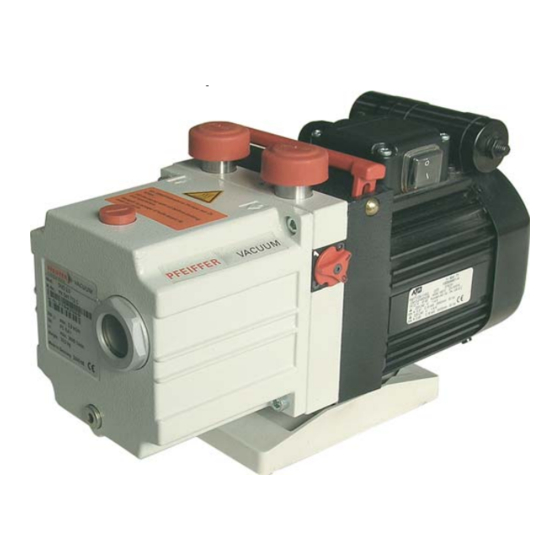
- Page 1 Betriebsanleitung • Operating Instructions Translation of the Original Operating Instructions Rotary Vane Pump UNO/DUO 2.5, DUO 2.5 C UNO 5...
-
Page 2: Table Of Contents
Table of contents Table of contents About this manual ......... 3 Validity . -
Page 3: About This Manual
1 About this manual 1.1 Validity This operating manual is for customers of Pfeiffer Vacuum. It describes the func- tioning of the designated product and provides the most important information for safe use of the unit. The description follows applicable EU guidelines. All informa- tion provided in this operating manual refer to the current state of the product's de- velopment. - Page 4 About this manual Pictograph Prohibition of an action or activity in connection with a definitions source of danger, the disregarding of which may result in serious accidents. Warning of a displayed source of danger in connection with operation of the unit or equipment. Command to perform an action or task associated with a source of danger, the disregarding of which may result in serious accidents.
-
Page 5: Safety
• Use of the vacuum pump to generate pressure. • Pumping of liquids. • The use of operating fluids not specified by Pfeiffer Vacuum. • Connection to pumps or units which are not suitable for this purpose according to their operating instructions. -
Page 6: Transport And Storage
Transport and storage 3 Transport and storage 3.1 Transport Transport instructions Remove the locking cap from the vacuum and exhaust flange immediately be- fore connecting! – Check the cone strainer, paying attention to the o-ring. Use only the handle on the top side of the pump to lift the pump. Fig. -
Page 7: Product Description
Product description 4 Product description 4.1 Product identification To correctly identify the product when communicating with Pfeiffer Vacuum, al- ways have the information from the rating plate available and use it: • Pump model and model number • Type and amount of operating fluid •... -
Page 8: Function
Gas ballast valve Casing O-ring O-ring 4/49 Fig. 3: UNO/DUO 2.5 Rotary vane vacuum pump 5 Installation 5.1 Setting up the pump Installation location Observe the following requirements when setting up the pump: • Note the load-bearing capacity of the mounting surface •... -
Page 9: Filling Up The Operating Fluid
Performance data of the pump are determined with the standard operating fluid. These can deviate from the default values when using other certified operating fluids. Use application-specific operating fluid only after consultation with Pfeiffer Vacuum. Unscrew operating fluid filler screw 3. -
Page 10: Connecting The Vacuum Side
Installation – Check operating fluid daily in non-stop operation, otherwise whenever the pump is switched on. Refilling is possible when the pump is in final vacuum operation. WARNING Toxic vapours! Danger of poisoning when igniting and heating synthetic operating fluids (e.g. F4/F5) above 300°C. -
Page 11: Connecting To The Mains Power Supply
Installation Choose the cross-section of the exhaust line to be at least the size of the nominal connection diameter of the vacuum pump's exhaust connection. Piping to the pump must be suspended or supported. – Physical forces from the piping system must not be allowed to act on vacuum pumps. - Page 12 Installation Fig. 6: Motor circuit diagram with switch Changing the voltage range Only valid for pumps with reversible motor: The mains voltage must be determined on-site each time before the pump is in- stalled or moved to a different location. ...
-
Page 13: Operation
Operation 6 Operation 6.1 Before switching on the pump Check the operating fluid level in the sightglass. Compare the voltage and frequency information on the rating plate with the mains voltage and frequency values. Check that the exhaust connection allows free flow (max. permissible pressure 1.5 bar absolute). - Page 14 Set flushing gas pressure; maximum pressure 1.2 bar (absolute). – Select the type and amount of flushing gas depending on the process; consult Pfeiffer Vacuum if necessary. Use the proportioning screw 7.3 to set the desired amount of gas.
- Page 15 Operation Fig. 9: Solenoid valve for controlling the gas ballast inlet Performance data of the solenoid valve 2/2 way valve closed when disconnected Supply voltage 24 VDC, +/- 10 % Power input Socket Type 2506 Threaded connection of flus- 1/8" inside hing gas Flushing gas pressure max.
-
Page 16: Switching Off The Pump
Maintenance 6.4 Switching off the pump The pump can be switched off in any pressure range. Rotary vane pumps have an integrated safety valve on the intake side. If the differ- ential pressure between the exhaust side and the intake side is ≥ 250 mbar, then the valve closes automatically and vents the pump when the pump is switched off. -
Page 17: Changing The Operating Fluid
Checklist for inspec- Certain repair and overhaul work should only be performed by Pfeiffer Vacuum Service (PV). Pfeiffer Vacuum will be released from all warranty and liability claims tion, maintenance if the required intervals for inspection, maintenance, or overhaul are exceeded or... - Page 18 Maintenance Fill the specimen in a test tube or some similar vessel and test by holding against the light. The level of deterioration of operating fluid P3 can be read off the colour scale in accordance with DIN 51578; request the supplementary sheet PK 0219 BN or download it from the Internet.
-
Page 19: Decommissioning
Decommissioning NOTE Request safety data sheets for operating fluids and lubricants from Pfeiffer Vacuum or download them from the Internet. Dispose of operating fluid according to the local regulations. 8 Decommissioning 8.1 Shutting down for longer periods Before shutting down the pump, observe the following procedure and adequately protect the pump system against corrosion: ... -
Page 20: Malfunctions
Thermal protection switch has Detect and fix cause of overheating; Pump will not start responded allow pump to cool off if necessary. Clean pump; contact Pfeiffer Vacuum Pump system dirty Service if necessary. Clean and overhaul pump; contact Pfeif- Pump system damaged fer Vacuum Service if necessary. - Page 21 Service if necessary NOTE Service work should be carried out by qualified personal only! Pfeiffer Vacuum is not liable for any damage to the pump resulting from work carried out improperly. Take advantage of our service training programs; additional information at www.pfeiffer-vacuum.net.
-
Page 22: Service
Fill out the "Service Request" form and send it by fax or e-mail to your Pfeiffer Vacuum service address. Include the confirmation on the service request from Pfeiffer Vacuum with your shipment. Fill in the contamination declaration and enclose it in the shipment (required!). -
Page 23: Spare Parts
Please state all information on the rating plate when ordering spare parts. Other spare parts than those described in this manual must not be used without the agreement of Pfeiffer Vacuum. Set of seals The set of seals contains all seals including all o-rings of the assembly groups and the subassemblies. - Page 24 Spare parts Spare parts Parts according to the exploded view on the follow- package ing page Set of seals PK E00 002 -T 13.1, 14 , 100, 101, 102, 103, 104, 105, 106, 107, 108, 109*, 110. Set of vanes PK E08 003 -T 12.4, 12.10, 12.15 PK E08 004 -T...
- Page 25 Spare parts Exploded view Intake connection Exhaust connection Coupling half Valve plate Cone strainer Motor Gas ballast valve O-ring (Fig. see Chap. 6.3) O-ring (Fig. see Chap. 1/108 6.3) Valve flap/gas ballast val- 2/108 Support stand Casing 102/ Handle Pump system (UNO) Pump system (DUO) 12.4 Vane 12.10 Hydraulic vane...
-
Page 26: Accessories
ONF 16, oil mist filter for pumping speeds of up to 2.5-5 m PK Z40 003 PK Z40 003 Oil return unit from ONF 16 to DUO 2.5 PK 194 315-T PK 194 315-T STP 016, dust separator, single-stage for minor contamination... -
Page 27: Technical Data
Technical data 13 Technical data Parameter UNO 2.5 DUO 2.5 Flange (in) DN 16 ISO-KF DN 16 ISO-KF Flange (out) DN 16 ISO-KF DN 16 ISO-KF Pumping speed at 50 Hz 2.5 m 2.5 m Pumping speed at 60 Hz 2.9 m... -
Page 28: Dimensions
Technical data 13.1 Dimensions DN 16 ISO-KF 185.5 31.5 173.5 32.5 Fig. 11: Dimensions for motor versions: 95 ... 105 V, 50 Hz / 100 ... 115V, 60 Hz DN 16 ISO-KF 173.5 31.5 32.5 Fig. 12: Dimensions for motor versions: 190 ... 210 V, 50 Hz / 200 ... 220 V, 60 Hz; 220 ... - Page 29 Technical data DN 16 ISO-KF 31.5 (8.5) 32.5 Fig. 13: Dimensions for motor versions: 115/230, 50/60 Hz DN 16 ISO-KF 181.5 31.5 32.5 Fig. 14: Dimensions for motor versions: 100 ... 105 V, 50 Hz / 110 ... 130 V, 60 Hz...
-
Page 30: Declaration Of Conformity
In addition, the product cited below satisfies all relevant provisions of EC Direc- tive "Electromagnetic Compatibility" 2004/108/EC . The agent responsible for compiling the technical documentation is Mr. Sebasti- an Oberbeck, Pfeiffer Vacuum GmbH, Berliner Straße 43, 35614 Aßlar. ® DuoLine /DuoLine™... - Page 31 Roots pumps Dry compressing pumps Leak detectors Valves Components and feedthroughs Vacuum measurement Gas analysis System engineering Service Pfeiffer Vacuum Technology AG · Headquarters/Germany Tel. +49-(0) 64 41-8 02-0 · Fax +49-(0) 64 41-8 02-2 02 · info@pfeiffer-vacuum.de · www.pfeiffer-vacuum.net...
Need help?
Do you have a question about the Duo 2.5 and is the answer not in the manual?
Questions and answers