Table of Contents
Advertisement
Quick Links
Advertisement
Table of Contents

Related Manuals for IFM ZZ1102


Summary of Contents for IFM ZZ1102
- Page 1 Instructions for set-up I/O module ZZ1102 N² P⁄N¹...
-
Page 2: Table Of Contents
9 Set-up � � � � � � � � � � � � � � � � � � � � � � � � � � � � � � � � � � � � � � � � � � � � � � � � � � � � � � � � � � � � � � � � � � � � � � � � � � � 11 1 Preliminary note Instructions, technical data, approvals, accessories and further information at www�ifm�com� You will find detailed instructions, technical data, approvals and further information using the QR code on the unit / packaging or at www�ifm�com�... -
Page 3: Safety Instructions
► Only use the set for support as an assistance system� 3 Functions and features The ZZ1102 set digitises all kinds of input signals for the O3M 3D sensor� Moreover, the output signals of the O3M 3D sensor can be processed in an analogue or digital way�... -
Page 4: Items Supplied
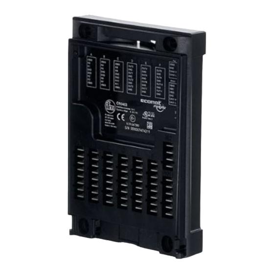
ZZ1102 I/O module 4 Items supplied ● 1x CR0403 BasicController, pre-programmed The BasicController is delivered pre-programmed� If ordered separately, the BasicController is not pre-programmed� ● 1x EC0401 cover with cable seal for BasicController ● 1x E3M171 CAN/power adapter cable to connect the BasicController to the O3M 3D sensor ●... -
Page 5: Installation
ZZ1102 I/O module 6 Installation Detailed instructions for mounting can be found in the mounting instructions of the BasicController CR0403� NOTE The BasicController can be damaged at the mounting location 'motor'� ► Mount the BasicController to the mounting location 'bodywork'�... -
Page 6: 7�1 Wiring Of The O3M 3D Sensor
ZZ1102 I/O module 7.1 Wiring of the O3M 3D sensor ① Power supply and CAN bus Shield 24 V CAN High CAN Low Fig� 4: Wiring of the O3M 3D sensor, back 7.2 Wiring of the BasicController The supply cables, CAN interfaces and input/outputs are connected via 6�3 x 0�8 mm blade male terminals on the front of the BasicController�... - Page 7 ZZ1102 I/O module Block CR0403 Pre-programming analogue voltage input IN 00 A/D 12 bits 0...32000 mV analogue current input IN 01 A/D 12 bits 0 … 20 mA IN 02���03 binary voltage inputs IN 04���07 binary voltage inputs IN 08 Internal use linked with logic O3M →...
-
Page 8: 7�2�1 Connect Basiccontroller
ZZ1102 I/O module The output of the digital outputs via the CAN bus must be activated using the ifm Vision Assistant software: ► Start ifm Vision Assistant. ► Connect 3D sensor with ifm Vision Assistant. ► Click [Application] function: ► Click [Logic] function: ►... - Page 9 ZZ1102 I/O module Mounting the cover: ► Pull out the locking lever (1) and rotate it towards you� ► Place the cover diagonally onto the BasicController (2). To do this, insert the two guide brackets (3) into the slots provided in the BasicController�...
-
Page 10: Operating And Display Elements
ZZ1102 I/O module 8 Operating and display elements The status LED of the BasicController indicates the operating states of the system by means of colour and clocking� P/N1 1: Status LED of the BasicControllers (green/red) 2: LED lighting in the cover... -
Page 11: Set-Up
The BasicController is pre-programmed for the application (→ 7.2, Table 1 ) and can be put into operation directly after installation and electrical connection� If further input and output signals are required, they can be defined in the logic of the O3M 3D sensor with the help of ifm Vision Assistant.
Need help?
Do you have a question about the ZZ1102 and is the answer not in the manual?
Questions and answers