
Related Manuals for IFM AL1202


Summary of Contents for IFM AL1202
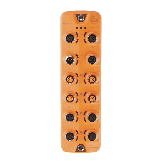
- Page 1 > > Operating Instructions IO-Link Master with PROFINET Interface PowerLine 8 Ports IP 65 / IP 66 / IP 67 AL1202 Firmware: 2.2.x or higher LR DEVICE: 1.4.0.x or higher English...
- Page 2 IO-Link Master with PROFINET Interface PowerLine 8 Ports IP 65 / IP 66 / IP 67 Contents Preliminary note Legal and copyright information ................... 5 Purpose of the document ..................... 5 Explanation of Symbols ....................... 6 Modification history ......................6 Safety instructions General ..........................
- Page 3 IO-Link Master with PROFINET Interface PowerLine 8 Ports IP 65 / IP 66 / IP 67 Set-up Read device and diagnostic information ................21 Configuration LR DEVICE ........................23 9.1.1 Remarks ............................. 24 9.1.2 IoT: Configure access rights ....................... 25 9.1.3 IoT: Configure the interface to the LR SMARTOBSERVER ............26 9.1.4 Fieldbus: Set PROFINET interface .....................
- Page 4 IO-Link Master with PROFINET Interface PowerLine 8 Ports IP 65 / IP 66 / IP 67...
- Page 5 Legal and copyright information 33117 © All rights reserved by ifm electronic gmbh. No part of this manual may be reproduced and used without the consent of ifm electronic gmbh. All product names, pictures, companies or other brands used on our pages are the property of the respective rights owners: ...
- Page 6 IO-Link Master with PROFINET Interface PowerLine 8 Ports IP 65 / IP 66 / IP 67 Explanation of Symbols 34171 WARNING! Death or serious irreversible injuries may result. CAUTION! Slight reversible injuries may result. NOTICE! Property damage is to be expected or may result. Important note Non-compliance can result in malfunction or interference Information...
- Page 7 IO-Link Master with PROFINET Interface PowerLine 8 Ports IP 65 / IP 66 / IP 67 Safety instructions Content General ..............................7 Required background knowledge ......................7 Safety symbols on the device ........................ 7 Tampering with the unit ......................... 7 28333 >...
- Page 8 IO-Link Master with PROFINET Interface PowerLine 8 Ports IP 65 / IP 66 / IP 67 Intended use Content Permitted use ............................8 Prohibited use ............................8 34079 > Permitted use 34211 The IO-Link master serves as a gateway between intelligent IO-Link devices and the PROFINET network.
- Page 9 IO-Link Master with PROFINET Interface PowerLine 8 Ports IP 65 / IP 66 / IP 67 Function Content Communication, parameter setting, evaluation ................... 10 Digital inputs ............................11 IO-Link supply ............................11 Voltage output ............................. 11 33836...
- Page 10 34583 The device provides the following configuration options: Parameter setting of the IO-Link master of the AL1202 with parameter setting software LR DEVICE and/or PROFINET projection software Parameter setting of the connected IO-Link devices (sensors, actuators) with parameter setting software LR DEVICE and/or PROFINET projection software ...
- Page 11 IO-Link Master with PROFINET Interface PowerLine 8 Ports IP 65 / IP 66 / IP 67 Digital inputs 33817 The device has 4 additional digital inputs (type 2 according to EN 61131-2). The digital inputs are on pin 2 of the IO-Link ports X01...X04. All inputs refer to the potential of the device supply (pin 3).
- Page 12 IO-Link Master with PROFINET Interface PowerLine 8 Ports IP 65 / IP 66 / IP 67 Mounting Content Mount the device ..........................12 34058 > Mount the device 34059 ► Disconnect the system from power before installation. ► For installation choose a flat mounting surface. ►...
-
Page 13: Notes
IO-Link Master with PROFINET Interface PowerLine 8 Ports IP 65 / IP 66 / IP 67 Electrical connection Content Notes ..............................13 Ethernet ports ............................14 IO-Link Ports ............................15 Connect the device ..........................16 33805 > Notes 51957 A qualified electrician must connect the unit. ►... -
Page 14: Ethernet Ports
IO-Link Master with PROFINET Interface PowerLine 8 Ports IP 65 / IP 66 / IP 67 Ethernet ports 34576 ► Connect the unit via the M12 socket X21 and/or X22 with the PROFINET network (e.g. PROFINET PLC, additional PROFINET device) ... -
Page 15: Io-Link Ports
IO-Link Ports 52465 Notes on wiring: The IO-Link ports of the AL1202 meet the requirements of the IO-Link specifications 1.0 to 1.1.2. The connected IO-Link devices must be supplied exclusively via the IO-Link master. The additional digital inputs IO-Link ports X01...X04 (pin 2) have a type 2 behaviour according to the standard EN61131-2. -
Page 16: Connect The Device
IP 65 / IP 66 / IP 67 or higher (→ Accessories (→ S. 42)) When using connectors longer than 25 m keep in mind the voltage drop as well as the required minimum voltage supply of the AL1202. - Page 17 IO-Link Master with PROFINET Interface PowerLine 8 Ports IP 65 / IP 66 / IP 67 Operating and display elements Content Overview .............................. 17 LED indicators ............................. 18 34063 > Overview 34582 Status LEDs RDY, BF and SF → Status LEDs (→...
- Page 18 IO-Link Master with PROFINET Interface PowerLine 8 Ports IP 65 / IP 66 / IP 67 LED indicators 34047 The device only has the following LED indicators: > 7.2.1 Status LEDs 34549 The RDY LED shows the status of the gateway. The BF LED (Bus Failure) shows the status of the PROFINET connection.
- Page 19 IO-Link Master with PROFINET Interface PowerLine 8 Ports IP 65 / IP 66 / IP 67 7.2.3 Voltage supply 34590 The interface for voltage supply (X31) has the LEDs that are marked as US and UA. The LEDs indicate the status of the voltage supply: Description Status LED green...
- Page 20 Content Read device and diagnostic information ..................... 21 52476 When the supply voltage has been switched on, the AL1202 starts with the factory settings. The display elements signal the current operating status (→ Operating and display elements (→ S. 17)).
- Page 21 ► Connect laptop/PC and AL1202 via the Ethernet internet. ► Start web browser. ► Enter the IP address of the AL1202 into the address field of the browser and press [ENTER] to confirm. > Web browser shows the web interface of the device.
- Page 22 IO-Link Master with PROFINET Interface PowerLine 8 Ports IP 65 / IP 66 / IP 67 Configuration Content LR DEVICE ............................23 PROFINET ............................32 33858...
-
Page 23: Table Of Contents
Firmware: Reset device to factory settings ..................29 Firmware: Reboot the device ......................30 Configure IO-Link devices ........................31 33692 On delivery, the AL1202 is configured with the factory settings (→ Factory settings (→ S. 41)). Required software: LR DEVICE (1.4.0.x or higher) (art.-no.: QA0011/QA0012) -
Page 24: Remarks
IO-Link master and the connected IO-Link devices without being connected to the AL1202 (OFFLINE mode). The configuration created in this way can be stored as a file (*.lrp) and loaded to the AL1202 and activated at a later date. -
Page 25: Iot: Configure Access Rights
IO-Link Master with PROFINET Interface PowerLine 8 Ports IP 65 / IP 66 / IP 67 9.1.2 IoT: Configure access rights 34046 The access rights define which instance may read and / or write the parameter data, process data and event/diagnostic messages. -
Page 26: Iot: Configure The Interface To The Lr Smartobserver
500 ms milliseconds) 2147483647 2147483647 ms Source identifier of the IO-Link master in the Factory setting: AL1202 [Application Tag] structure of the LR SMARTOBSERVER (String32) After changing the parameter [Port LR SMARTOBSERVER] or [Application Tag], it may take 120 seconds before the device establishes a new TCP connection. -
Page 27: Io-Link Ports: Activate Data Transfer To The Lr Smartobserver
IO-Link Master with PROFINET Interface PowerLine 8 Ports IP 65 / IP 66 / IP 67 9.1.5 IO-Link ports: Activate data transfer to the LR SMARTOBSERVER 33690 The user can decide separately for each IO-Link port if the process data of the connected IO-Link devices should be transferred to the LR SMARTOBSERVER. -
Page 28: Io-Link Ports: Configure Operating Mode
IO-Link Master with PROFINET Interface PowerLine 8 Ports IP 65 / IP 66 / IP 67 9.1.6 IO-Link ports: Configure operating mode 33694 The IO-Link ports X01...X08 of the device support the following operating modes: Digital input (DI): binary input signal at pin 4 (C/Q) of the IO-Link port ... -
Page 29: Io-Link Ports: Set The Device Validation And Data Storage
IO-Link master are restored automatically on the IO-Link device. ID of the manufacturer that is to Factory setting: 0 [Vendor ID] be validated ifm electronic: 310 65535 ID of the IO-Link device that is to Factory setting: 0 [Device ID] be validated 16777215 ►... -
Page 30: Firmware: Reboot The Device
When rebooting the device, all settings are kept. To restart the AL1202: ► Select [Firmware] menu. > The menu page shows the current settings. ► Click on [Reboot] to reboot the device. > LR DEVICE reboots the ifm IO-Link master. -
Page 31: Configure Io-Link Devices
► Under [ONLINE]: Click on the required IO-Link master. > LR DEVICE automatically detects the IO-Link devices connected to the IO-Link master (e.g. ifm sensor KG5065). Configure IO-Link device ► Mouse click on the port to which the IO-Link device is connected. -
Page 32: Install Gsd Files
► Launch the PROFINET projection software. ► Install the GSD file of the AL1202. Once the GSD file is installed, the AL1202 is in the hardware catalogue in the following folder: > [PROFINET IO] > [Addiotional Field Devices] > [IO] > [ifm electronic]... -
Page 33: Integrate The Io-Link Master In The Project
► Create and configure PROFINET controller and coupling units. ► Create and configure PROFINET connection. ► Drag the [AL1202] node from the hardware catalogue and drop it on the PROFINET connection. > The AL1202 is displayed as part of the PROFINET network. -
Page 34: Configure Io-Link Ports
IO-Link Master with PROFINET Interface PowerLine 8 Ports IP 65 / IP 66 / IP 67 9.2.4 Configure IO-Link ports 52481 You can access the configuration of the IO-Link ports via the slots 1.2 ... 1.9 of the AL1202. The following assignment applies IO-Link port of the AL1202 Slot... -
Page 35: Configure Io-Link Devices
Configure IO-Link devices 52482 The AL1202 supports the configuration of the connected IO-Link devices via the PROFINET application. The configurable parameters depend on the IO-Link device that is used. Configurable parameters of the IO-Link devices: → IO Device Description (IODD) of the IO-... -
Page 36: Read And Write Cyclic Process Data
IO-Link Master with PROFINET Interface PowerLine 8 Ports IP 65 / IP 66 / IP 67 9.2.6 Read and write cyclic process data 52483 While the IO-Link ports are being configured, IEC addresses are generated automatically for inputs and outputs as well as the PQI byte. To enable access to the cyclic process data in the application, the user must couple the IEC addresses with symbolic variables. -
Page 37: Read I&M Datasets
IO-Link Master with PROFINET Interface PowerLine 8 Ports IP 65 / IP 66 / IP 67 9.2.7 Read I&M datasets 52484 I&M0 provide the user with device-specific basic information. This ensures reliable identification of the device, the device's hardware and software components as well as the manufacturer. The datasets I&M1 to 3 offer the programmer the possibility to store project-specific information on the device. - Page 38 IO-Link Master with PROFINET Interface PowerLine 8 Ports IP 65 / IP 66 / IP 67 Maintenance, repair and disposal Content Cleaning process ..........................38 Firmware update ..........................39 Replace IO-Link device ........................40 51990 The operation of the unit is maintenance-free. ►...
- Page 39 ► Enter the following into the address field of the browser and press [ENTER] to confirm: http://<IP address of the device>/web/update > Web browser shows the [Firmware Update] page. Load new firmware to AL1202 ► Click on [Select file]. > Dialogue window appears.
- Page 40 ► Save changes. Replace IO-Link device ► Disconnect old IO-Link device from IO-Link master. ► Connect new IO-Link device with the same IO-Link port of the AL1202. > IO-Link master copies parameter values from the data memory to the new IO-Link device.
- Page 41 IO-Link Master with PROFINET Interface PowerLine 8 Ports IP 65 / IP 66 / IP 67 Factory settings 34594 In the factory settings, the device has the following parameter settings: Factory setting Parameters 0.0.0.0 [IP address] 0.0.0.0 [Subnet mask] 0.0.0.0 [IP gateway address] blank [PROFINET name]...
- Page 42 IO-Link Master with PROFINET Interface PowerLine 8 Ports IP 65 / IP 66 / IP 67 Accessories 33870 List of accessories of AL1202: → www.ifm.com > Product page > Accessories...
- Page 43 IO-Link Master with PROFINET Interface PowerLine 8 Ports IP 65 / IP 66 / IP 67 Appendix Content Technical data ............................. 44 PROFINET ............................49 33879...
-
Page 44: Application
IO-Link Master with PROFINET Interface PowerLine 8 Ports IP 65 / IP 66 / IP 67 13.1 Technical data Content Application ............................44 Electrical data ............................45 Inputs / outputs ............................ 46 Inputs ..............................46 Outputs ..............................46 Interfaces ............................. 46 Operating conditions.......................... -
Page 45: Electrical Data
IO-Link Master with PROFINET Interface PowerLine 8 Ports IP 65 / IP 66 / IP 67 13.1.2 Electrical data 33808 Electrical data 20...30 DC; (US; to SELV/PELV) Operating voltage [V] 300...3900; (US) Current Consumption [mA] Protection class Sensor supply US Max. -
Page 46: Inputs / Outputs
IO-Link Master with PROFINET Interface PowerLine 8 Ports IP 65 / IP 66 / IP 67 13.1.3 Inputs / outputs 34068 Inputs / outputs 12; (configurable) Total number of inputs and outputs Number of digital inputs: 12; Number of digital outputs: 8 Number of Inputs and Outputs >... -
Page 47: Operating Conditions
IO-Link Master with PROFINET Interface PowerLine 8 Ports IP 65 / IP 66 / IP 67 13.1.7 Operating conditions 34062 Operating conditions Indoor use Applications -25...60 Ambient temperature [°C] -25...85 Storage temperature [°C] Max. perm. relative air humidity [%] 2000 Max. -
Page 48: 13.1.10 Electrical Connection
IO-Link Master with PROFINET Interface PowerLine 8 Ports IP 65 / IP 66 / IP 67 13.1.10 Electrical connection 34573 Voltage supply IN X31 Connector + 24 V DC (US) Wiring GND (UA) GND (US) +24 V DC (UA) Voltage supply OUT X32 Connector + 24 V DC (US) Wiring... - Page 49 IO-Link Master with PROFINET Interface PowerLine 8 Ports IP 65 / IP 66 / IP 67 13.2 PROFINET Content Parameter data ............................ 49 Cyclic data ............................52 Acyclic data ............................54 33674 > 13.2.1 Parameter data 34546 Subslot Name Description Slot Master Parameter data of the IO-Link master (→...
- Page 50 Supported IO-Link standard and no check and clear [Validation / Data no verification of the vendor ID and behaviour of the AL1202 when a new Storage] device ID IO-Link device is connected to the IO- no data storage Link port ...
- Page 51 ID and device ID) The IO-Link master stores the parameter values of the connected IO-Link device once if the data memory of the AL1202 is empty. When connecting an IO-Link device with factory settings, the parameter values stored in the IO-...
- Page 52 IO-Link Master with PROFINET Interface PowerLine 8 Ports IP 65 / IP 66 / IP 67 13.2.2 Cyclic data Content PROFINET modules ..........................52 PQI (Port Qualifier Information) ......................53 33814 > PROFINET modules 34539 Description Module 32 bytes input and output data and PQI IO-Link 32I/32O + PQI 16 bytes input and output data and PQI IO-Link 16I/16O + PQI...
- Page 53 IO-Link Master with PROFINET Interface PowerLine 8 Ports IP 65 / IP 66 / IP 67 PQI (Port Qualifier Information) 34530 Port Qualifier Information (PQI) contains diagnostic information about the IO-Link port. In addition to the process data, the IO-Link master sends the PQI to the PROFINET controller. Legend: ...
- Page 54 Acyclic data Content I&M datasets ............................54 Diagnostic and alarms ......................... 56 33868 > I&M datasets 34555 The AL1202 supports the following I&M datasets (I&M = Identification & Maintenance): > I&M0 (Slot 0) 34545 Description Access* Size Variable IO-Link ID of the manufacturer...
- Page 55 IO-Link Master with PROFINET Interface PowerLine 8 Ports IP 65 / IP 66 / IP 67 I&M3 (Slot 0) 34550 Description Access* Size Variable Description of the device (ASCII, padded with spaces) Descriptor * ... r/w = read and write >...
- Page 56 IO-Link Master with PROFINET Interface PowerLine 8 Ports IP 65 / IP 66 / IP 67 Diagnostic and alarms 34533 Name Description Type code EVNT_CODE_M_PDU_CHECK Receive frame with CRC error Alarm 0x02 EVNT_CODE_S_RETRY Repetitions detected Alarm 0x1B EVNT_CODE_P_SHORT Short circuit on C/Q cable detected Diagnostics 0x1E EVNT_CODE_P_SENSOR...
- Page 57 IO-Link Master with PROFINET Interface PowerLine 8 Ports IP 65 / IP 66 / IP 67 IO-Link ports Index Activate data transfer to the LR SMARTOBSERVER ........27 Configure operating mode................28 Set the device validation and data storage........... 29 IO-Link Ports ..................
- Page 58 IO-Link Master with PROFINET Interface PowerLine 8 Ports IP 65 / IP 66 / IP 67 Status LEDs ................... 18 Tampering with the unit ................7 Technical data ..................44 Visual indication ..................10 Voltage output ..................11 Voltage supply ..................19 VPN connection ..................
Need help?
Do you have a question about the AL1202 and is the answer not in the manual?
Questions and answers