Table of Contents
Advertisement
Advertisement
Table of Contents

Related Manuals for IFM CR2016


Summary of Contents for IFM CR2016
- Page 1 Device manual Input/output module CabinetModule CR2016...
-
Page 2: Table Of Contents
CabinetModule CR2016 Contents 1 Preliminary note � � � � � � � � � � � � � � � � � � � � � � � � � � � � � � � � � � � � � � � � � � � � � � � � � 3 1�1 Symbols used�... -
Page 3: Preliminary Note
CabinetModule CR2016 1 Preliminary note Technische Daten, Zulassungen, Zubehör und weitere Informationen unter www�ifm�com� 1.1 Symbols used ► Instruction > Reaction, result […] Designation of keys, buttons or indications → Cross-reference Important note Non-compliance may result in malfunction or interference�... -
Page 4: Safety Instructions
SELV voltage of which is not grounded� The terminals may only be supplied with the signals indicated in the technical data or on the unit label and only the approved accessories of ifm electronic gmbh may be connected�... -
Page 5: Functions And Features
CabinetModule CR2016 3 Functions and features The device enables decentralised evaluation of sensor signals and decentralised triggering of actuators and proportional valves� WARNING The device is not approved for safety tasks with respect to the protection of persons� 4 Function ●... -
Page 6: Mounting
CabinetModule CR2016 5 Mounting 5.1 Mounting location The device is to be mounted in a dry and enclosed environment (e�g� control panel of the driver‘s cab, separate control boxes, etc�)� The housing must not be exposed to any torsion forces or mechanical stress�... -
Page 7: 5�3 Cooling
CabinetModule CR2016 5.3 Cooling ► As the internal heating of the electronics is conducted away via the housing, ensure sufficient heat dissipation� 6 Electrical connection 6.1 Connectors The supply cables, interfaces and inputs/outputs are connected via AMP crimp connectors on the front of the unit�... -
Page 8: 6�2 Fuses
CabinetModule CR2016 Pin connection → 9 Technische Daten 9 Technical data ► Close unused connectors with unconnected sockets� Information about the available connector accessories at: www�ifm�com 6.2 Fuses To protect the whole system (wiring and module) the individual electric circuits must be protected�... -
Page 9: Set-Up
CabinetModule CR2016 7 Set-up 7.1 PLC configuration in CODESYS 2.3 Parameter setting of the device functions and of the CAN interface is directly done from the application programmed with CODESYS 2�3� To do so, the „Electronic Data Sheet“ (EDS) is integrated via the CODESYS PLC configuration�... -
Page 10: 7�2 Plc Configuration In Codesys 3�5
CabinetModule CR2016 7.2 PLC configuration in CODESYS 3.5 The „Electronic Data Sheet“ (EDS) is installed in the [Device Repository]� Proceed as follows in the main menu: ► Click on [Tools] / [Device Repository]� ► Select [Fieldbuses] / [CiA CANopen] / [CiA Remote Device] and click on [In- stall]�... -
Page 11: 7�2�2 Syncmonitoring
7.3 Electronic Data Sheet The EDS contains the description of all parameters and I/O data of the device in a format defined by CANopen� The EDS files are provided for all CANopen slaves by ifm electronic� The EDS files are available at www�ifm�com�... -
Page 12: Parameter Setting
CabinetModule CR2016 8 Parameter setting 8.1 Automatic saving Automatic saving of the communication and device parameters can be activated or deactivated by means of the “save parameter” entry (object directory, index 1010, S-Idx 01)� ● Value 0x00: There is no automatic saving� Changed parameters are only valid until the device is switched off or until the next reset�... -
Page 13: 8�4 Manufacturer-Specific Profiles; Idx 2000 To 5Fff
CabinetModule CR2016 Parameters Index in Default value (factory Change saved Change object preset) automatically effective directory Event Timer Tx PDO 1 1800 05 0x00 adjustable immediately COB-ID Tx PDO 2 1801 01 0x280 + node ID adjustable after PreOp Trans Type Tx PDO 2... -
Page 14: 8�5 Emcy Objects
CabinetModule CR2016 8.5 EMCY objects The following error codes are supported according to DSP-301 and DSP-401: EMCY Error Zusatz Beschreibung Code Code 0x2110 0x03 bit-coded "Device Specific" 0001 analogue input 1 excessive current 0010 analogue input 2 excessive current 0100 analogue input 3 excessive current... -
Page 15: Technical Data
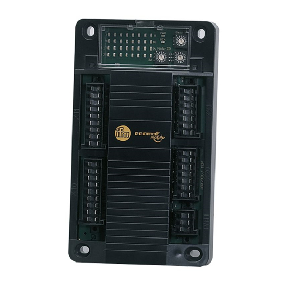
1 LED green (PWR) 1 LED red (diagnosis, DIA) 32 LEDs yellow (status of the inputs / outputs) ifm electronic gmbh • Friedrichstraße 1 • 45128 Essen We reserve the right to make technical alterations without prior notice! CR2016 / page 1... - Page 16 PWM preset value < 1% measuring range binary output switched (ON) analogue output: PWM preset value > 2% measuring range ifm electronic gmbh • Friedrichstraße 1 • 45128 Essen We reserve the right to make technical alterations without prior notice! CR2016 / page 2 01.10.2015...
- Page 17 0.7 U switch-off level 0.3 U input resistance 45 kΩ input frequency max. 50 Hz ifm electronic gmbh • Friedrichstraße 1 • 45128 Essen We reserve the right to make technical alterations without prior notice! CR2016 / page 3 01.10.2015...
- Page 18 EN 50155 clause 12.2 mechanical/climatic tests EN 50121-3-2 EMC noise emission and noise immunity additional information on request ifm electronic gmbh • Friedrichstraße 1 • 45128 Essen We reserve the right to make technical alterations without prior notice! CR2016 / page 4 01.10.2015...
- Page 19 = pulse (low side) = supply outputs = binary (low side) = PWM (high side) ifm electronic gmbh • Friedrichstraße 1 • 45128 Essen We reserve the right to make technical alterations without prior notice! CR2016 / page 5 01.10.2015...
-
Page 20: Maintenance, Repair And Disposal
CabinetModule CR2016 10 Maintenance, repair and disposal As the module does not contain any components which must be maintained by the user, the housing must not be opened� The maintenance of the module may only be carried out by the manufacturer�... - Page 21 CabinetModule CR2016 Index S-Idx Name Default Beschreibung 1008 device name CR2016 1009 HW Version HW Vx�x 100A SW Version SW Vx�x 100C guard time 0x0000 time in ms within this time the module expects a "node guarding" of the network master...
- Page 22 CabinetModule CR2016 Index S-Idx Name Default Beschreibung COB ID Receive 0x00000300 + PDO is valid (bit 31 = 0) PDO 2 NodeID transmission type Rec 0x01 0x01���0xF0 = synch cyclic PDO 2 0xFE���0xFF = asynch (immediately) 1402 highest numbered 0x02...
- Page 23 CabinetModule CR2016 Index S-Idx Name Default Beschreibung 4th mapping object 0x10041464 index 6414 subindex 4, 16 bits Rec PDO 2 5th mapping object 0x00000000 no object Rec PDO 2 6th mapping object 0x00000000 no object Rec PDO 2 7th mapping object...
- Page 24 CabinetModule CR2016 Index S-Idx Name Default Beschreibung 8th mapping object 0x00000000 no object Rec PDO 4 1800 highest numbered 0x05 subindex Transmit PDO 1 COB ID Transmit 0x00000180 + PDO is valid (bit 31 = 0) PDO 1 NodeID transmission type 0xFF 0x01���0xF0 = synch cyclic...
- Page 25 CabinetModule CR2016 Index S-Idx Name Default Beschreibung inhibit timer Trans 0x0000 min� interval for transmission (in 100µs) PDO 4 event timer Trans 0x0000 max transfer break in trans type "asynch" PDO 4 (0���65535ms) when this time has elapsed the PDO is transferred even if the appl� event...
- Page 26 CabinetModule CR2016 Index S-Idx Name Default Beschreibung 1st mapping object 0x20011220 index 2012, subindex 1, 32 bits Trans PDO 3 2nd mapping object 0x20021220 index 2012, subindex 2, 32 bits Trans PDO 3 3rd mapping object 0x00000000 no object Trans PDO 3...
- Page 27 CabinetModule CR2016 Index S-Idx Name Default Beschreibung configuration binary 0x0A 0x00 = off input 3 0x0A = binary input 0x0B = binary input with diagnosis 0x0E = frequency input configuration binary 0x0A 0x00 = off input 4 0x0A = binary input...
- Page 28 CabinetModule CR2016 Index S-Idx Name Default Beschreibung configuration 0x03 0x00 = off analogue input 3 0x03 = voltage 0���10,000 mV 0x06 = ratiometric 0���1000 per mille 0x07 = current 0���20,000 µA 0x09 = voltage 0���30,000 mV 0x0A = binary input...
- Page 29 CabinetModule CR2016 Index S-Idx Name Default Beschreibung configuration binary 0x02 0x00 = off output 10 0x02 = binary output 0x04 = analogue output (PWM 100 Hz) 0x0F = binary output with diagnosis configuration binary 0x02 0x00 = off output 11...
- Page 30 CabinetModule CR2016 Index S-Idx Name Default Beschreibung 20F1 CANopen node ID 0x20 The entries 20F0/20F1 must always contain identical values� The new entries are valid after a reset (swit- ching the module off/on)� Values outside the permissible ranges will be rejected�...
- Page 31 CabinetModule CR2016 Index S-Idx Name Default Beschreibung 16bit user variable 8 16bit user variable 9 16bit user variable 10 2520 number of 32bit user 0x0A variables 32bit user variable 1 32bit user variable 2 32bit user variable 3 32bit user variable 4...
- Page 32 CabinetModule CR2016 Index S-Idx Name Default Beschreibung analogue output 5 0x00 0��10 per 10% analogue output 6 0x00 0��10 per 10% analogue output 7 0x00 0��10 per 10% analogue output 8 0x00 0��10 per 10% analogue output 9 0x00 0��10 per 10%...
Need help?
Do you have a question about the CR2016 and is the answer not in the manual?
Questions and answers