Sign In
Upload
Download
Table of Contents
Contents
Add to my manuals
Delete from my manuals
Share
URL of this page:
HTML Link:
Bookmark this page
Add
Manual will be automatically added to "My Manuals"
Print this page
×
Bookmark added
×
Added to my manuals
Manuals
Brands
IFM Manuals
I/O Systems
ioControl CR2050
Device manual
IFM ioControl CR2050 Device Manual
Hide thumbs
Also See for ioControl CR2050
:
Programming manual
(228 pages)
1
Table Of Contents
2
3
4
5
6
7
8
9
10
11
12
13
14
15
16
17
18
19
20
21
22
23
24
25
26
27
28
29
30
31
32
33
34
35
36
37
38
39
40
41
42
43
44
45
46
47
48
49
50
51
52
53
54
55
56
57
58
59
60
61
62
63
64
65
66
67
68
69
70
71
72
73
74
75
76
77
78
79
80
81
82
83
84
85
86
87
88
89
90
91
92
93
94
95
96
97
98
99
100
101
102
103
104
105
106
107
108
109
110
111
112
113
114
115
116
117
118
119
120
121
122
123
124
125
126
page
of
126
Go
/
126
Contents
Table of Contents
Bookmarks
Table of Contents
Table of Contents
Preliminary Note
1�1 Explanation of Symbols
Safety Instructions
2�1 General Safety Instructions
2�2 Target Group
2�3 Electrical Connection
2�4 Tampering with the Unit
Functions and Features
Function
Installation
5�1 Mounting Surface
5�2 Fixing
5�3 Cable Seal
Electrical Connection
6�1 General Electrical Connection
6�2 Connection Accessories
6�3 Frequency Inputs
6�4 Reverse Polarity Protection
6�5 Supply of the Signal Generators at the Inputs
6�6 Fuses
6�7 Examples for Connection Types
6�7�1 Cr2050
6�7�2 Cr2051
6�7�3 Cr2052
Operating and Display Elements
7�1 Menu Structure
7�2 Status Indication of the Inputs/Outputs (I/O Leds, Yellow)
Set-Up
8�1 I/O Module
8�1�1 Display Mode
8�1�2 Parameter Setting
8�1�3 List of Parameters
8�2 Controller
8�2�1 Programming
8�3 Required Documentation
8�4 Required Hardware
Technical Data
9�1 Cr2050
9�2 Cr2051
9�3 Cr2052
Maintenance, Repair and Disposal
10�1 Maintenance
10�2 Cleaning the Housing Surface
10�3 Repair
10�4 Disposal
Approvals/Standards
Appendix
12�1 EMCY Object
12�2 Object Directory Cr205X
12�2�1 Device-Specific CR2050
12�2�2 Device-Specific CR2051
12�2�3 Device-Specific CR2052
12�3 Sdos Error Messages
12�3�1 Cr2050
12�3�2 Cr2051
12�3�3 Cr2052
Advertisement
Quick Links
1
2�3 Electrical Connection
2
6�7�2 Cr2051
3
10�3 Repair
Download this manual
See also:
Programming Manual
Device manual
ioControl
UK
CR2050
CR2051
CR2052
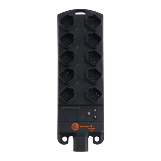
P_MZ_e100_0092
Original
30%
333,4%
Table of
Contents
Previous
Page
Next
Page
1
2
3
4
5
Advertisement
Table of Contents
Need help?
Do you have a question about the ioControl CR2050 and is the answer not in the manual?
Ask a question
Questions and answers
Related Manuals for IFM ioControl CR2050
Relays IFM BasicController CR0431 Programming Manual
(228 pages)
I/O Systems IFM SmartModul CR2512 Device Manual
Input/output module (27 pages)
I/O Systems IFM CR2016 Device Manual
Input/output module cabinetmodule (32 pages)
I/O Systems IFM CompactModule CR2032 Device Manual
Device manual input/output module (29 pages)
I/O Systems IFM ioControl CR2051 Device Manual
(126 pages)
I/O Systems IFM ioControl CR2052 Device Manual
(126 pages)
I/O Systems IFM CompactModule Metal CR2031 Device Manual
Output module (33 pages)
I/O Systems IFM SmartModule CR2520 Device Manual
Input/output module (33 pages)
I/O Systems IFM AL1202 Operating Instructions Manual
Io-link master with profinet interface (58 pages)
I/O Systems IFM AL4103 Operating Instructions Manual
Remote i/o module 16 di profinet ip65 / ip66 / ip67 / ip69k (69 pages)
I/O Systems IFM AL19 Series Operating Instructions Manual
Io-link master (11 pages)
I/O Systems IFM AL1330 Operating Instructions Manual
Io-link master with ethercat interface dataline 4 ports ip 65 / ip 66 / ip 67 (138 pages)
I/O Systems IFM AL4002 Operating Instructions Manual
Remote i/o module 16 di profinet ip65 / ip66 / ip67 (68 pages)
I/O Systems IFM AL1352 Operating Instructions Manual
Io-link master with iot interface (84 pages)
I/O Systems IFM AL1340 Operating Instructions Manual
Io-link master with modbus tcp interface dataline 4 ports ip 65 / ip 66 / ip 67 (129 pages)
I/O Systems IFM AL1950 Device Manual
Io-link master with iot interface cabinetline 8 ports ip 20 (110 pages)
This manual is also suitable for:
Iocontrol cr2051
Iocontrol cr2052
Table of Contents
Print
Rename the bookmark
Delete bookmark?
Delete from my manuals?
Login
Sign In
OR
Sign in with Facebook
Sign in with Google
Upload manual
Upload from disk
Upload from URL


Need help?
Do you have a question about the ioControl CR2050 and is the answer not in the manual?
Questions and answers