Table of Contents
Advertisement
Quick Links
Advertisement
Table of Contents

Related Manuals for IFM SmartModule CR2520


Summary of Contents for IFM SmartModule CR2520
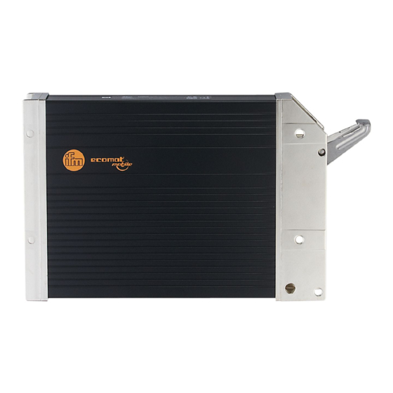
- Page 1 Device manual Input/output module SmartModule CR2520...
-
Page 2: Table Of Contents
SmartModule CR2520 Contents 1 Preliminary note � � � � � � � � � � � � � � � � � � � � � � � � � � � � � � � � � � � � � � � � � � � � � � � � � 4 1�1 Symbols used�... - Page 3 SmartModule CR2520 11 Appendix (UK)� � � � � � � � � � � � � � � � � � � � � � � � � � � � � � � � � � � � � � � � � � � � � � � � � 24 11�1 Object directory �...
-
Page 4: Preliminary Note
SmartModule CR2520 1 Preliminary note This document applies to devices of the type "SmartModule" (art� no�: CR2520)� It is deemed as a part of the device� This document is intended for specialists� These specialists are people who are qualified by their appropriate training and their experience to see risks and to avoid possible hazards that may be caused during operation or maintenance of the device�... -
Page 5: Safety Instructions
SELV voltage of which is not grounded� The connection terminals may only be supplied with the signals indicated in the technical data and/or on the device label and only the approved accessories of ifm electronic may be connected� 2.4 Housing temperature According to the technical specifications below the device can be operated in a wide ambient temperature range�... -
Page 6: 2�5 Tampering With The Device
SmartModule CR2520 2.5 Tampering with the device In case of malfunctions or uncertainties please contact the manufacturer� Tampering with the device can seriously affect the safety of operators and machinery� It is not permitted and leads to the exclusion of any liability and warranty claims�... -
Page 7: Functions And Features
SmartModule CR2520 3 Functions and features The CR2520 I/O module enables decentralised evaluation of sensor signals and decentralised triggering of actuators and DC motors� ● The module supports binary/analogue inputs/outputs and is therefore classified in the device class "I/O module" to CiA DS 401�... -
Page 8: Installation
SmartModule CR2520 4 Installation 4.1 Fixing ► Fix the device to a flat surface using 4 M5 screws� Screw material: steel or stainless steel Tightening torque: 8 ±2 NOTE Use screws with a low head to avoid that the connector is damaged when placed and locked�... -
Page 9: 4�3 Mounting Surface
SmartModule CR2520 4.3 Mounting surface NOTE The housing must not be exposed to any torsional forces or mechanical stress� ► Use compensating elements if there is no flat mounting surface available� Mounting surface 4.4 Heat dissipation ► Ensure sufficient heat dissipation as the internal heating of the electronics is conducted away via the housing�... -
Page 10: Electrical Connection
SmartModule CR2520 5 Electrical connection 5.1 Wiring Wiring (→ 7 Technical data) Only connect the connector pins as shown in the pin layout� Unspecified connector pins remain unconnected� ► Connect all indicated supply cables and GND terminals� 5.2 Ground connection ►... -
Page 11: Set
SmartModule CR2520 6 Set-up 6.1 PLC configuration in CODESYS 2.3 Parameter setting of the device functions and of the CAN interface is directly done from the application programmed with CODESYS 2�3� To do so, the "Electronic Data Sheet" (EDS) is integrated via the CODESYS PLC configuration�... -
Page 12: 6�2 Plc Configuration In Codesys 3�5
SmartModule CR2520 6.2 PLC configuration in CODESYS 3.5 The "Electronic Data Sheet“ (EDS) is installed in the [Device Repository]� Proceed as follows in the main menu: ► Click on [Tools] / [Device Repository]� ► Select [Fieldbuses] / [CiA CANopen] / [CiA Remote Device] and click on [Install]�... -
Page 13: 6�2�2 Syncmonitoring
6.3 Electronic Data Sheet The EDS contains the description of all parameters and I/O data of the device in a format defined by CANopen� The EDS files are provided for all CANopen slaves by ifm electronic� The EDS files are available at www�ifm�com�... -
Page 14: Technical Data
CANopen, CiA DS 301 version 4, CiA DS 401 version 2�1 Node ID (CANopen) hex 20 (= dec 32) adjustable via CANopen object directory ifm electronic gmbh • Friedrichstraße 1 • 45128 Essen We reserve the right to make technical alterations without prior notice! CR2520 / page 1 29�01�2018... -
Page 15: 7�2 Indicators, Test Standards And Regulations
10���500 Hz; 0�72 mm/10 g; 10 cycles/axis ISO 16750-3: 2007 Bumps 30 g/6 ms; 24,000 shocks ifm electronic gmbh • Friedrichstraße 1 • 45128 Essen We reserve the right to make technical alterations without prior notice! CR2520 / page 2 29�01�2018... -
Page 16: 7�3 Input Characteristics
(B Input frequency 1 kHz Switch-on level > 0�7 U Switch-off level < 0�2 U ifm electronic gmbh • Friedrichstraße 1 • 45128 Essen We reserve the right to make technical alterations without prior notice! CR2520 / page 3 29�01�2018... -
Page 17: 7�4 Output Characteristics
Switching current, static ≤ 5 A Total current ≤ 10 A Inrush current, peak ≤ 30 A ifm electronic gmbh • Friedrichstraße 1 • 45128 Essen We reserve the right to make technical alterations without prior notice! CR2520 / page 4 29�01�2018... - Page 18 Total current ≤ 24 A Inrush current, peak ≤ 90 A Short-circuit proof and overload protected ifm electronic gmbh • Friedrichstraße 1 • 45128 Essen We reserve the right to make technical alterations without prior notice! CR2520 / page 5 29�01�2018...
-
Page 19: 7�5 Wiring
H-bridge function pulse-width modulation supply sensors/module supply outputs ifm electronic gmbh • Friedrichstraße 1 • 45128 Essen We reserve the right to make technical alterations without prior notice! CR2520 / page 6 29�01�2018... -
Page 20: Parameter Overview
SmartModule CR2520 8 Parameter overview 8.1 General Automatic saving of the communication and device parameters can be activated or deactivated by means of the "save parameter" entry (see object directory, index 1010)� When the value 0x02 is entered into SIdx 01, all parameters are automatically saved if changes were made�... -
Page 21: 8�3 Communication Profiles; Index 1000 To 1Fff
SmartModule CR2520 8.3 Communication profiles; index 1000 to 1FFF Parameters Index in Default value Change saved Change object (factory set) automatically effective directory COB ID Sync Object 1005 0x80 adjustable after reset Communication Cycle 1006 0x00 (Off) adjustable immediately Guard Time... -
Page 22: 8�4 Emcy Objects
SmartModule CR2520 The life time factor 0 is interpreted as 1� The first guard protocol is interpreted as "start guarding" even if guarding is not yet active at that time (guard time =0)� 8.4 EMCY objects The following error codes according to DSP-401 or DSP-301 are supported:... -
Page 23: Maintenance, Repair And Disposal
SmartModule CR2520 9 Maintenance, repair and disposal The device is maintenance-free ► Do not open the housing as the device does not contain any components which can be repaired by the user� The device must only be repaired by the manufacturer�... -
Page 24: Appendix (Uk)
SmartModule CR2520 11 Appendix (UK) 11.1 Object directory 11.1.1 Manufacturer-specific profiles; index 2000 to 6FFF Index S-Idx Name Type Default Description 2000 number of IOs 0x1A configuration analog input 1 0x03 0x00 = off Chan 01 0x03 = 0 … 10�000 mV 0x06 = ratiometric 0 …... - Page 25 SmartModule CR2520 Index S-Idx Name Type Default Description configuration binary input 9 0x01 0x00 = off Chan 13 0x01 = binary input configuration binary input 10 0x01 0x00 = off Chan 14 0x01 = binary input configuration binary input 11...
- Page 26 SmartModule CR2520 Index S-Idx Name Type Default Description 2001 PWM frequency binary outputs 0xFA (250 Hz) 20���250 Hz PWM frequency for binary outputs 1…3 Chan 16, 17, 18 2002 number analog inputs analogue input 1 depends on IO configuration analogue input 2...
- Page 27 SmartModule CR2520 Index S-Idx Name Type Default Description 2014 number PWM outputs set value PWM chan 16 PWM value 0 … 1000 out 0 set value PWM chan 17 PWM value 0 … 1000 out 1 set value PWM chan 18 PWM value 0 …...
-
Page 28: Communication Profiles; Index 1000 To 1Fff
SmartModule CR2520 11.1.2 Communication profiles; index 1000 to 1FFF Index S-Idx Name Type Default Description 1000 device type 0x000F0191 I/O-module profile DS401 digital/analogue inputs/outputs 1001 error register 0x00 1003 pre-definded error field 0x00 up to 4 entries in error history supported... - Page 29 SmartModule CR2520 Index S-Idx Name Type Default Description consumer heartbeat time 0x00000000 heartbeat monitoring time for node n monitoring of only one node is supported 0x0nntttt = monitoring time [ms] 0x0nntttt = node number (if nn or tttt = 0, no monitoring is carried...
- Page 30 SmartModule CR2520 Index S-Idx Name Type Default Description 7th mapping object Rec PDO 1 0x00000000 no object 8th mapping object Rec PDO 1 0x00000000 no object 1601 number of application objects 0x04 linked with Rec PDO 2 1st mapping object Rec PDO 2...
- Page 31 SmartModule CR2520 Index S-Idx Name Type Default Description inhibit timer Trans PDO 1 0x0000 min� interval for transmission (in 100µs) event timer Trans PDO 1 0x0000 max transfer break in trans type "asynch" (0���65535ms) when this time has elapsed the PDO is transferred even if the appl�...
- Page 32 SmartModule CR2520 Index S-Idx Name Type Default Description 2nd mapping object Trans 0x00000000 no object PDO 1 3rd mapping object Trans 0x00000000 no object PDO 1 4th mapping object Trans 0x00000000 no object PDO 1 5th mapping object Trans 0x00000000...
- Page 33 SmartModule CR2520 Index S-Idx Name Type Default Description 6th mapping object Trans 0x00000000 no object PDO 3 7th mapping object Trans 0x00000000 no object PDO 3 8th mapping object Trans 0x00000000 no object PDO 3 1A03 number of application objects...
Need help?
Do you have a question about the SmartModule CR2520 and is the answer not in the manual?
Questions and answers