Table of Contents
Advertisement
Quick Links
Advertisement
Table of Contents

Related Manuals for IFM DSU100


Summary of Contents for IFM DSU100
- Page 1 Operating instructions IO-Link data memory DSU100...
-
Page 2: Table Of Contents
DSU100 IO-Link data memory Contents Preliminary note ............. -
Page 3: Preliminary Note
Supplementary note 1.2 Legal and copyright information © All rights reserved by ifm electronic gmbh. No part of these instructions may be reproduced and used without the consent of ifm electronic gmbh. All product names, pictures, companies or other brands used on our pages are the property of the... -
Page 4: Safety Instructions
DSU100 IO-Link data memory 2 Safety instructions • The unit described is a subcomponent for integration into a system. – The system architect is responsible for the safety of the system. – The system architect undertakes to perform a risk assessment and to create documentation in accordance with legal and normative requirements to be provided to the operator and user of the system. -
Page 5: Intended Use
IO-Link data memory DSU100 3 Intended use The IO-Link storage device saves data in non-volatile memory in industrial environments. Data is exchanged and device parameters are set via the IO-Link interface. The device is typically used for identifying interchangeable tools or plant components. -
Page 6: Installation
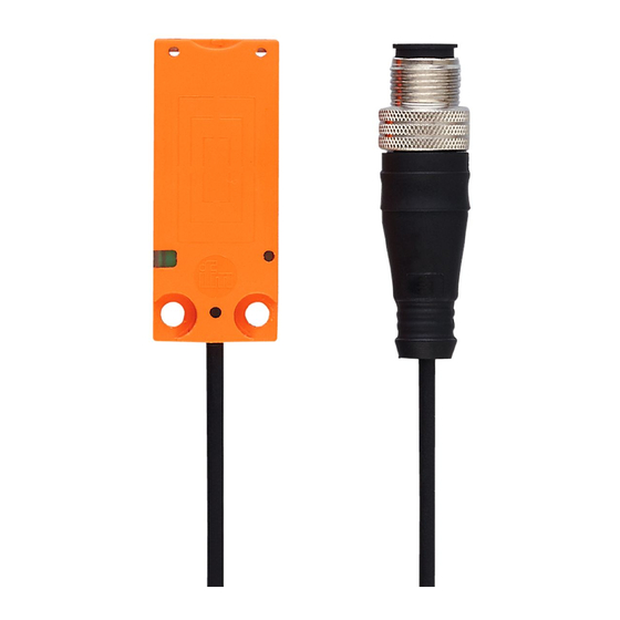
DSU100 IO-Link data memory 4 Installation Information about available accessories at www.ifm.com 4.1 Mechanical design Fig. 1: Device 4.2 Installation on tanks with mounting adapter Fig. 2: Installing the device with mounting adapter The mounting adapter is available as an accessory (article number E12153). Installing the device with the mounting adapter: u Insert the top of the device (1) into the mounting adapter. -
Page 7: Electrical Connection
The electrical supply must only be made via PELV/SELV circuits. u Disconnect power before connecting the device. Connecting the device: u Connect the device to the IO-Link master using the M12 connector. w Voltage is supplied via the IO-Link master. Information about available accessories at www.ifm.com... -
Page 8: Operating And Display Elements
DSU100 IO-Link data memory 6 Operating and display elements Fig. 4: Light indicators 1 multicolour LED State Green LED Yellow LED Ready for operation Green LED is permanently on Successful reading/writing from/to IO- Yellow LED flashes briefly 1x Link memory Error when reading/writing from/to IO-... -
Page 9: Function
Necessary information about the IODD, process data structure, diagnostic information, parameter addresses and the required hardware and software can be found at www.ifm.com. 7.1.3 Device-specific parameters The parameters of the device are set using an IO-Link parameter setting program (for example ifm moneo). w More information about the IODD at www.ifm.com. - Page 10 DSU100 IO-Link data memory The addressed memory area for the read/write operation cannot be outside the memory area of the device: u Address for auto-read/auto-write + data length for auto-read/auto-write ≤ number of available bytes on the device The minimum length for auto-read/auto-write is 2 bytes and the maximum length is 28 bytes.
-
Page 11: Operation
IO-Link data memory DSU100 8 Operation The device supports different operating modes. An operating mode is set with the command value in the process data output image. Command value Operating mode 0x00 Read 0x01 Auto-read data 0x02 Auto-write data 0x03 Read data... -
Page 12: Read Uid" Operating Mode
DSU100 IO-Link data memory 8.3 "Read UID” operating mode In the „Read UID“ operating mode, the of the device is read and provided by the latter at the process data input. The UID cannot be changed and deleted. The UID is individually assigned to each device at the factory. -
Page 13: Auto-Write Data" Operating Mode
IO-Link data memory DSU100 The data in the process image is updated as soon as the memory contents change. The data in the process image is valid as soon as the status bit "Cmd End" is set. Byte Process data output... -
Page 14: Read Data" Operating Mode
DSU100 IO-Link data memory If writing was unsuccessful, an error value is shown in the process image. Byte Process data output Process data input command value = 0x02 command value = 0x02 status status data 0 data 0 data 1... -
Page 15: Successfully Reading" Example
IO-Link data memory DSU100 u The device transfers the data to the process data output image (data 0 to 27) and increases the block counter by 1. u The controller acknowledges receipt of the data by increasing the block counter in the process data output image by 1. -
Page 16: Reading Not Executed" Example
DSU100 IO-Link data memory Process data output image Process data input image Preset com- 0x00 0x00 0x00 0x00 0x00 0x00 0x00 0x00 mand Controller sets 0x03 0x12 0x23 0x00 0x00 0x03 0x00 0x00 command (read 35 bytes from address 0x12) -
Page 17: Write Data" Operating Mode
IO-Link data memory DSU100 Controller with- 0x00 0x00 0x00 0x00 0x00 0x03 0x00 0x01 0x22 draws command value The device car- 0x00 0x00 0x00 0x00 0x00 0x00 0x00 0x00 ries out the pre- set command 8.7 "Write data" operating mode In the "Write data" operating mode more than 28 bytes can be written with one write operation. The data is sequentially transferred from the controller to the device. -
Page 18: Successfully Writing" Example
DSU100 IO-Link data memory Process data output when Process data output during Byte Process data input starting the write operation data transfer ignored data 14 0x00 ignored data 15 0x00 ignored data 16 0x00 ignored data 17 0x00 ignored data 18... -
Page 19: Writing Not Executed" Example
IO-Link data memory DSU100 8.7.2 “Writing not executed” example The example shows a write command abort. Process data output image Process data input image Preset com- 0x00 0x00 0x00 0x00 0x00 0x00 0x00 0x00 mand Controller sets 0x04 0x10 0x00 0x00... - Page 20 DSU100 IO-Link data memory Byte Process data output Process data input ignored ignored ignored ignored ignored ignored ignored ignored ignored ignored ignored ignored ignored ignored ignored ignored ignored ignored ignored ignored Error value...
-
Page 21: Maintenance, Repair And Disposal
IO-Link data memory DSU100 9 Maintenance, repair and disposal The operation of the unit is maintenance-free. Only the manufacturer is allowed to repair the unit. u After use dispose of the device in an environmentally friendly way in accordance with the... -
Page 22: Approvals/Standards
DSU100 IO-Link data memory 10 Approvals/standards For approvals and standards, the following information is available: • Test standards and regulations: documentation.ifm.com • EU declaration of conformity and approvals: documentation.ifm.com • Notes relevant for approval: package inserts of the device... - Page 23 IO-Link data memory DSU100 List of figures Fig. 1 Device..........................Fig. 2 Installing the device with mounting adapter................. Fig. 3 Installing the device without mounting adapter..............Fig. 4 Light indicators........................
-
Page 24: Glossary
DSU100 IO-Link data memory Glossary IODD Digital description of the device. The IODD is required for device parameter setting via IO-Link. Unique Identification Number; unique identification number of a device.
Need help?
Do you have a question about the DSU100 and is the answer not in the manual?
Questions and answers