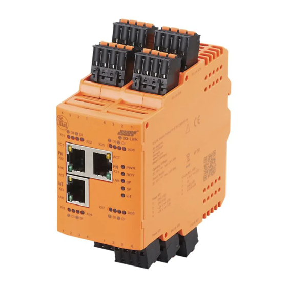
IFM AL19 Series Operating Instructions Manual

IFM AL19 Series Operating Instructions Manual

Io-link master

Advertisement

Operating instructions
IO-Link master
UK
AL19xx

Advertisement

Table of Contents
loading

Summary of Contents for IFM AL19 Series

  • Page 1 Operating instructions IO-Link master AL19xx...
  • Page 2: Preliminary Note

    1 Preliminary note Technical data, approvals, accessories and further information at www.ifm.com. 2 Safety instructions • The device described is a subcomponent for integration into a system. - The manufacturer is responsible for the safety of the system. - The system manufacturer undertakes to perform a risk assessment and to create a documentation in accordance with legal and normative requirements to be provided to the operator and user of the system.
  • Page 3: Installation Instructions

    Important note Non-compliance may result in malfunction or interference. 4.1 Warnings used WARNING Warning of serious personal injury. Death or serious irreversible injuries may result. 4.2 Safety symbols on the device General warning on the device. When this symbol appears, consider the corresponding section in the operating instructions.
  • Page 4: Electrical Connection

    WARNING ► Do not open the devices. ► Do not insert any objects into the devices. ► Prevent metal foreign bodies from penetrating. 6 Electrical connection The device must be connected by a qualified electrician. The national and international regulations for the installation of electrical equipment must be adhered to.
  • Page 5 AL1900 / AL1920 / AL1930 / AL1940 / AL1950 IO-Link Power supply U Terminal IO-Link A ports X01...X08 IN X 31 Sensor supply L+ (U GND (U GND (U Sensor supply L- (U + 24 V DC (U C/Q IO-Link + 24 V DC (U AL1900 AL1920...
  • Page 6 6.3 Interfaces AL1900 / AL1920 AL1930 / AL1940 AL1950 LEDs LEDs AL1900 AL1920 AL1930 AL1940 AL1950 Voltage Voltage Voltage Voltage Voltage supply supply supply supply supply 8 IO-Link 8 IO-Link 8 IO-Link 8 IO-Link 8 IO-Link A ports A ports A ports A ports A ports...
  • Page 7: Factory Settings

    8 Parameter setting The parameter setting and configuration of the field bus interface is done via the higher-level PLC. As an option, the connected IO-Link devices can be configured with the ifm software LR DEVICE. 9 Maintenance, repair, disposal The device is maintenance-free.
  • Page 8: Scale Drawing

    10 Scale drawing AL1900 / AL1920 AL1930 / AL1940 105,3 100,6 AL1950 105,3 100,6...
  • Page 9: Terminal Arrangement

    10.1 Terminal arrangement AL1900 / AL1920 AL1930 / AL1940 AL1950 AL1950...
  • Page 10: Technical Data

    11 Technical data Electrical data Operating voltage [V] 20...30 DC; (U ; to SELV/PELV) Current consumption [mA] 300...3900; (U Protection class Sensor supply U Total current rating [A] Environmental conditions Application Control cabinet Ambient temperature [°C] -25...65 Storage temperature [°C] -25...85 Max.

This manual is also suitable for:

Al1900Al1920Al1930Al1940Al1950

Table of Contents