Table of Contents
Advertisement
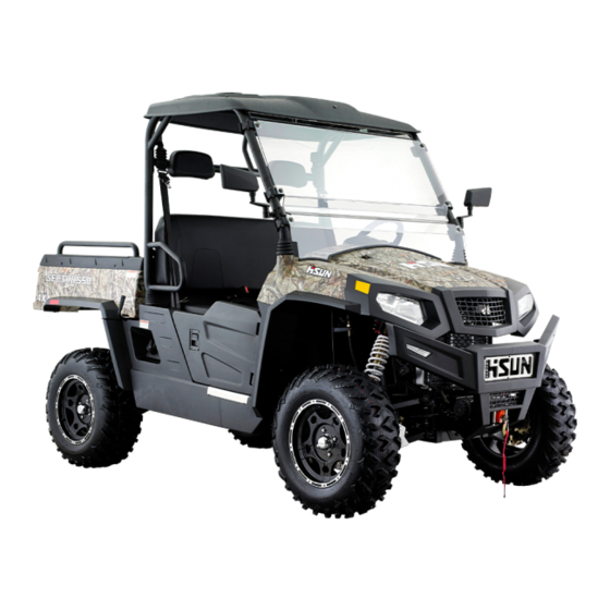
Congratulations on your purchase of the HS294-2. This Owner's / Operator's
manual will provide you information regarding safe operation, operational
instructions, maintenance and care. Fully understanding this manual and following
all of the instructions herein will provide the knowledge needed to have safe and
enjoyable vehicle operation.
If you have any questions regarding the operation or maintenance of your
UTV, please
call Monkija Trail Park Oy at 0086-23-61020546 or go to Pajalantie 6a 37550,
Lempaala,
Finland.
IMPORTANT SAFETY MESSAGES
● READ THIS MANUAL CAREFULLY AND COMPLETELY BEFORE OPERATING YOUR
UTV.
MAKE SURE YOU UNDERSTAND ALL INSTRUCTIONS.
● PAY CLOSE ATTENTION TO THE WARNING AND CAUTION LABELS ON THE UTV.
● NEVER OPERATE THE UTV WITHOUT PROPER TRAINING OR INSTRUCTION.
● THIS UTV SHOULD NOT BE RIDDEN BY ANYONE UNDER
16 YEARS OF AGE.
Introduction HS 294-2
INTRODUCTION
1-1
Advertisement
Table of Contents
Troubleshooting

Related Manuals for Hisun HS294-2


Summary of Contents for Hisun HS294-2
- Page 1 Introduction HS 294-2 INTRODUCTION Congratulations on your purchase of the HS294-2. This Owner’s / Operator’s manual will provide you information regarding safe operation, operational instructions, maintenance and care. Fully understanding this manual and following all of the instructions herein will provide the knowledge needed to have safe and enjoyable vehicle operation.
-
Page 2: Important Manual Information
Introduction HS 294-2 IMPORTANT MANUAL INFORMATION FAILURE TO FOLLOW THE WARNINGS CONTAINED IN THIS MANUAL CAN RESULT IN Particularly important information is distinguished in SERIOUS INJURY OR DEATH. this manual by the following notations: The Safety Alert Symbol means ATTENTION! YOUR SAFETY IS INVOLVED! - Page 3 Introduction HS 294-2 Failure to follow WARNING instructions could result in severe injury or death to the machine operator, bystander or a person inspecting or repairing the machine. A CAUTION indicates special precautions that must be taken to avoid damage to the machine.
-
Page 4: Important Notice
Introduction HS 294-2 IMPORTANT NOTICE This vehicle is designed and manufactured for ON - ROAD use only. This vehicle complies with all applicable ON - ROAD noise level and spark arrester laws and regulations in effect at the time of manufacture. Please check your local riding laws and regulations before operating this vehicle. - Page 5 Introduction HS 294-2 seconds between each start attempt.
- Page 6 Introduction HS 294-2 NIVERSAL SYMBOLS As a guide to the operation of your vehicle, various universal symbols have been utilized on the instruments and controls. The symbols are shown below with an indication of their meaning. Safety Alert Symbol Lift Cylinder-Retract Diesel Fuel Lift Cylinder-Extend Engine coolant-Temperature...
- Page 7 Introduction HS 294-2...
-
Page 8: Table Of Contents
Introduction HS 294-2 Table of Contents Operating the engine Subject Page Starting the engine Introduction Cold starting Important manual information Stopping the engine Important notice Warming up Universal symbols Warm-up transmission oil in the low temperature range Location of parts Illustrated contents Operating the vehicle Safe operation... - Page 9 Introduction HS 294-2 Stopping Checking and Refueling 10-6 Fuel gauge Checking coolant level 10-6 Winch mount plate Cleaning radiator screen 10-7 Transporting vehicle Checking brake fluid level 10-7 Service intervals Checking brake pedal 10-8 Periodic service 10-1 Checking parking brake 10-8 How to open the front hood and 10-1...
- Page 10 Introduction HS 294-2 Replacing engine oil filter 10-15 Flushing Cooling system and changing coolant Replacing transmission oil 10-15 10-19 Checking brake pedal 10-16 Anti-freeze 10-20 Checking brake hose and pipe 10-16 Replacing radiator hose (water 10-21 pipes) Checking brake light switch 10-16 Replacing fuel hose 10-21...
-
Page 11: Location Of Parts
Introduction HS 294-2 Options 14-1 Statement 15-1 LOCATION OF PARTS 1-11... -
Page 12: Illustrated Contents
Hitch coupling device ILLUSTRATED CONTENTS 12-12... - Page 13 Hitch coupling device 12-13...
- Page 14 Hitch coupling device 12-14...
- Page 15 Hitch coupling device 12-15...
-
Page 16: Safety Instructions
Hitch coupling device All operators, including experienced vehicle Do not wear loosen articles of clothing during drivers or passengers, should carefully read and operation, as these can be drawn into moving fully understand this Users Manual, and operate parts on the vehicle and could cause a severe strictly as the manual states in order to achieve injury to occur. - Page 17 Hitch coupling device cab. It is suggested that children under age of 5 not be allowed as a passenger. 2) Single-row vehicle’s loading limit is 331lbs (150KG). Reduce the loading weight according to road conditions. Never exceed the weight limits for operation. Never allow unauthorized persons to repair this vehicle.
-
Page 18: Operation
Hitch coupling device and cause injury. turn at different speed. Otherwise, the vehicle may turnover. This vehicle is designed and manufactured for off-road use only, so never drive on paved 10. Never drive over terrain such as a ditch, a roadways. - Page 19 Hitch coupling device ① Trailer Hitch to children. Children under age of 5 are not be allowed in this vehicle. Do not accelerate quickly when starting the engine, especially driving on rough terrain as Never allow children to touch or climb the vehicle this can cause injury or death.
-
Page 20: Driving On A Slope
Hitch coupling device Always check for people or obstacles behind the Under all conditions, both operator and vehicle before shifting the vehicle into reverse. passengers should wear helmet Avoid a collision with an obstacle or person. protective equipment. Driver should slow down according to road Park the vehicle on a firm, flat area. - Page 21 Hitch coupling device 5. Driving in harsh conditions should be securely attached. Reduce loaded weight when driving on poor road conditions or steep inclines. Vehicle can be operated during the day or Do not put your hands and you body under under good light conditions.
-
Page 22: Parking
Hitch coupling device lowered, lock the cargo bed in place before down before checking the coolant level. Otherwise, you could be burned by hot fluid operating the vehicle. Never driving before or steam blown out. securing and locking the cargo bed. No smoking when adding electrolyte or refueling. - Page 23 Hitch coupling device Stop the vehicle and park it on level ground. Pull equipment by professionals. the parking brake and remove all cargo. Then Keeping specified tire pressure can help to place shift lever on “N” position, stop the engine ensure driving safety.
-
Page 24: Warning And Caution Labels
Hitch coupling device Warning and caution labels (1) (2) (3) (4) (5) (6) (7) 12-24... - Page 25 Hitch coupling device (8) (9) (10) (11) (12) 12-25...
-
Page 26: Servicing Of Vehicle
Hitch coupling device (13) (14) (15) SERVICING OF VEHICLE 12-26... -
Page 27: Specifications Table
Hitch coupling device Your dealer is interested in your new vehicle and has the desire to help you get the most value from it. After reading this manual thoroughly, you will find you can do some of the regular maintenance by yourself. - Page 28 Hitch coupling device Make HS191MR 1 cylinder, 4-cycle, gasoline, SOHC, liquid Type cooled compression ratio 9.6±0.1:1 Bore × stroke 91.0×84.0 Displacement(s) 546cc Engine Rated net power kW (HP) 20.0(28.83) Maximum power speed 6000 Maximum torque (Nm) 36 Maximum torque speed (rpm) 4700 Low idle speed (rpm) 1500±150...
- Page 29 Hitch coupling device Rear tyre track mm (in.) 1285 (50.59) Forward overhang mm (in.) 460 (18.11) Model Specification Rear overhang mm (in.) 600 (23.62) Ground Clearance mm (in.) 310 (12.2) Turning diameter m (in.) 8.6 (28.22) 350 (772) or Max. rolling weight (Towing Capacity) kg (lbs.) 200 (440) Payload capacity...
-
Page 30: Vehicle Limitations
Hitch coupling device VEHICLE LIMITATIONS The Vehicle has been thoroughly tested for proper performance with implements sold or approved by manufacturer. Use with implements which are not sold or approved and which exceed the maximum specifications listed below, or which are otherwise unfit for use, vehicle may result in vehicle malfunction or failures with a possibility of the vehicle damage, property damage and injury to the operator or others. - Page 31 Hitch coupling device Max. tongue weight 43 kg (95 lb.) 29 kg (64 lb.) 1. Above mentioned specifications are based on level ground condition. 12-31...
-
Page 32: Checking Coolant Level
Hitch coupling device DAILY CHECK To better prevent troubles, it is important to know condition of the vehicle well. Check it before starting. CAUTION: To avoid personal injury: Be sure to check and service the vehicle on a level surface with the engine shut off and the parking brake “ON”... - Page 33 Hitch coupling device -Check front and rear joint boots. -Check tire inflation pressure. -Refuel (See "DAILY CHECK" in "PERIODIC SERVICE" section.) -Check of danger, warning and caution labels (See "DANGER, WARNING AND CAUTION LABELS"in"SAFE OPERATION"section.) 12-33...
- Page 34 Hitch coupling device 12-34...
-
Page 35: Starting The Engine
Hitch coupling device NOTE: The parking brake warning lamp (P) comes CAUTION: on while parking brake is applied and goes off when it is released. To avoid personal injury: ⚫ Read "SAFE OPERATION" in front of this manual. ⚫ Read the danger, warning and caution labels located on the vehicle. - Page 36 Hitch coupling device ① Parking brake 12-36...
-
Page 37: Cold Starting
Hitch coupling device 3. Push the accelerator pedal down slowly. IMPORTANT: ⚫ Because of safety devices, the engine will not start except when the gear shift lever is placed in the “NEUTRAL” position and the brake is depressed. ■ Cold Starting When the ambient temperature is below - 15℃( 5℉), the engine is very cold. -
Page 38: Warm-Up Transmission Oil In The Low Temperature Range
Hitch coupling device START (Start the Engine) ■Warm-Up Transmission Oil in the Low Temperature Range IMPORTANT : IMPORTANT: ⚫ It is not sufficient to do daily checks on dash board only. Always conduct daily checks ⚫ Do not operate the vehicle under full carefully by referring to “DAILY CHECK“... -
Page 39: Operating The Vehicle
Hitch coupling device OPERATING NEW VEHICLE ■ Changing Lubricating Oil for New How a new vehicle is handled and maintained Vehicles determines the life of vehicle. The lubricating oil is especially important for A new vehicle just off the factory production a new vehicle. - Page 40 Hitch coupling device operating and riding the vehicle. Adjust the seat belts for proper fit and connect the buckle. This seat belt is an auto- locking retractable type. 12-40...
-
Page 41: Head Light Switch
Hitch coupling device ⑫ Emergency light "OFF" ⑬ Winch cable release ⑭ Winch cable pulled up NOTE: Turning the head light switch to the “ON” position causes the following lamps to light simultaneously. Tail lights (lamps at the rear portions of the vehicle) Lamp built in the coolant temperature gauge... - Page 42 Hitch coupling device ② Head lights “OFF” To indicate a right turn, push on the lower half of the turn toggle switch. ③ Left turning lights To indicate a left turn, push on the upper half ④ Right turning lights of the turn toggle switch.
-
Page 43: Brake Pedal
Hitch coupling device NOTE: loads. ⚫ ⚫ The turn signal light switch is only When driving on icy, wet or loose operative when the key switch is in the surface, make sure the vehicle is “ON” position. correctly loaded to avoid skidding or If the emergency light switch is pressed to loss of steering control. - Page 44 Hitch coupling device ⚫ If you shift gears while ascending or descending a slope, be prepared to ③ Tail turn signal lamp use the brake to maintain control. ⚫ Operate in reverse at slow speeds to maintain control. 3. Checking the brake pedal. The range gear shift lever can only be ■...
-
Page 45: Accelerator Pedal
Hitch coupling device correctly loaded to avoid skidding Select proper gear and engine speed and loss of steering control. Reduce depending on the types of job. the speed and engage front wheel Before exiting vehicle, shift the gear shift drive. lever to the “NEUTRAL”... - Page 46 Hitch coupling device ⚫ AN accident could occur through improper use of the gear shift lever ■ 4WD Lever CAUTION: To avoid personal injury: ⚫ when traveling at road speed. Use only 2WD. ⚫ When driving on icy, wet or loose ■...
- Page 47 Hitch coupling device ⚫ The engine suddenly slows down or To avoid personal injury: accelerates. ⚫ Do not remove radiator cap until ⚫ Unusual noises are suddenly heard. coolant temperature is well below its ⚫ Exhaust fumes suddenly become very boiling point.
- Page 48 Hitch coupling device ① Coolant temperature gauge The hour meter indicates in five digits the hours the vehicle has been used; the last digit indicates 1/10 of an hour. 12-48...
- Page 49 Hitch coupling device ① Hour meter The speedometer indicates the traveling speed. ① Speedometer 12-49...
- Page 50 Hitch coupling device WINCH MOUNT PLATE Always read and follow the instructions in the winch owner’s manual before attempting to install or use a winch. ① Winch mount plate ■ Transporting Vehicle Pay attention to the following points when transporting the vehicle. Use a suitable truck or trailer.
- Page 51 Hitch coupling device CAUTION: To avoid personal injury and vehicle damage: ⚫ Be sure you have sufficient knowledge, experience, the proper replacement parts and tools before you attempt any vehicle maintenance task. ⚫ If you don’t have the knowledge and equipment which are necessary to perform the maintenance task, consult your local dealer.
- Page 52 Hitch coupling device Indication of After Items 700 hrs 50 100 150 200 250 300 350 400 450 500 550 600 650 700 Every ◎ ○ ○ ○ Engine oil Change 200 hrs Every ○ ○ ○ Replace ◎ Engine oil filter 200 hrs Every Transmission...
- Page 53 Hitch coupling device Every 1 Clean years ○ ○ ○ ○ ○ ○ ○ *Air cleaner element Every Replace 100 hrs Every 1 ◎ ○ ○ ○ Brake pedal Check years Every ○ ○ ○ ◎ Parking brake Adjust 200 hrs Every Brake light ◎...
- Page 54 Hitch coupling device Every 2 Brake fluid Change years Remote Every 2 Replace hydraulic hose years Rear brake Every 2 Replace cylinder seal years Front brake Every 2 Replace seal years Every 2 Cooling system Flush years Indication of After Items 700 hrs 50 100 150 200 250 300 350 400 450 500 550 600 650 700...
- Page 55 Hitch coupling device ① Turn switch ② Front hood cover CAUTION: ■ Operator’s Seat To avoid personal injury: To open the seat, raise the seat to the forward position. HOW TO OPEN THE FRONT HOOD COVER AND SEAT CAUTION To avoid personal injury from contact with moving parts: ⚫...
- Page 56 Hitch coupling device Pull handle 1 driver's seat can move forward and backward, the seat is adjusted to adapt to the height of different drivers. HOW TO RAISE THE CARGO BED CAUTION To avoid personal injury: When servicing under raised bed, make ●...
- Page 57 Hitch coupling device The proper position. 3. Tighten the adjustment lever to secure the steering wheel in the desired position. ① Cargo bed handle ② UP ③ DOWN ◆ To lower the cargo bed Press down the cargo bed hard to make the gas spring contractive till it is locked.
- Page 58 Hitch coupling device NOTE: Never turn an adjusting mechanism beyond the minimum and maximum settings. Spring preload 1. Loosen the locknut. 2. Turn the spring preload adjusting nut in direction ⓐ to increase the spring preload and thereby harden the suspension, and in direction ⓑ...
- Page 59 Hitch coupling device the shock absorber assembly to a HSUN dealer for any service. The spring preload, rebound damping and compression damping forces of the front and rear shock absorber assemblies can be adjusted to suit the operating conditions. 1. Rebound damping force adjusting screw Compression damping force Turn the compression damping force adjusting screw (use 3.0 Allen wrench) in direction ⓐ...
- Page 60 Hitch coupling device Always tighten the locknut against the adjusting nut, and then tighten it to the 1.Compression damping force adjusting screw specified torque. WARNING Rebound damping force ·Suspension components become hot Turn the rebound damping force adjusting during operation. Never touch the screw in direction S to increase the rebound compression damping force adjusting damping force and thereby harden the...
- Page 61 Hitch coupling device ① Jack ② Rear frame tube ■ Front End DAILY CHECK Jack up at the front frame tube only. For your own safety and maximum service life of the vehicle, make a thorough daily inspection before starting the engine and operating the vehicle.
- Page 62 Hitch coupling device ■ Checking and Refueling CAUTION To avoid personal injury: ⚫ Do not smoke while refueling. ⚫ Be sure to stop the engine before refueling. Turn the key switch to “ON”, check the amount of fuel by the fuel gauge. Fill fuel tank when fuel gauge shows1/4 or less fuel in tank.
- Page 63 Hitch coupling device safety support. coolant in EVERY 2 YEARS in PERIODIC To check the oil level, draw out the SERVICE section) dipstick, wipe it clean, replace it, and draw it out again, check to see if the level is too low, add new oil to the prescribed level on the dipstick.
- Page 64 Hitch coupling device ① Radiator screen ① Recovery tank ② FULL ③ LOW IMPORTANT ⚫ Radiator screen must be cleaned from IMPORTANT debris to prevent engine from overheating ⚫ If the radiator cap has to be removed, follow the cautions above and securely re ■...
- Page 65 Hitch coupling device ⚫ Detach the screen and remove all foreign Use extreme care when filling the materials, reservoir. If brake fluid spill on power steering hose, wash off with water immediately, as brake fluid quickly ruins synthetic resin or rubber hoses. Check to see that the brake fluid level is up to the LOWER mark.
-
Page 66: Checking Gauges Meter And Easy Checker Lamps
Hitch coupling device 2. If it is below the “LOWER” mark add brake with the key switch in the "ON" position and fluid . the parking brake indicator should come on. To release the parking brake, depress the parking pedal. Make sure the parking brake warning lamp on the display goes off when parking brake is applied. -
Page 67: Checking Seat Belt And Rops
Hitch coupling device ■ Checking seat belt and ROPS Always check condition of seat belt and ROPS attaching hardware before operating vehicle. Replace if damaged. ■ Checking joint boot ① Brake pedal ② FREE TRAVEL Check to see if the joint boots are ③... -
Page 68: Checking Tire Inflation Pressure
Hitch coupling device EVERY 50 HOURS damaged or not. ■ Greasing 2. If the boots are cut crashed or show signs of deterioration, consult your local Apply a small amount of multi-purpose grease to the following points every 50 hours. If you dealer. - Page 69 Hitch coupling device Though the tire pressure is factory-set to the ② Parking brake pivot(spray type grease) prescribed level, it naturally drops slowly in the course of time, thus check it every day and inflate as necessary. tire sizes inflation pressure Front: 225/65-14 100kPa (14psi) Rear: 275/55-14...
-
Page 70: Checking Engine Start System
Hitch coupling device ① Range gear shift lever pivot (spray type grease ) ① Range gear shift lever ■ Checking engine start system ■ Checking wheel bolt torque CAUTION CAUTION TO avoid personal injury To avoid personal injury ⚫ Do not allow anyone near the vehicle ⚫... - Page 71 Hitch coupling device Turn the key to “START” position. The engine must not crank. If it cranks consult your local dealer for this service. ① Torque wheel bolts to 75to 90 N.m 12-71...
-
Page 72: Cleaning Air Cleaner Primary Element
Hitch coupling device ■ Cleaning air cleaner primary element Remove the air cleaner cover and primary element. Remove the sponge material from its frame. Wash the sponge material gently but thoroughly in solvent. Squeeze the excess solvent out of the sponge material and let it dry. - Page 73 Hitch coupling device ⚫ Be sure to refit the cower with the arrow (on the rear of cower ) upright if the cover is improperly fitted the evacuator valve will not function and dust will adhere to the element. ◆ Evacuator Valve Open the air cleaner cover once a week under ordinary conditions –or daily when used in a dusty place-to get rid of large particles of dust...
-
Page 74: Checking Battery Condition
Hitch coupling device ◆Check fuel line and fuel filter. CAUTION To avoid personal injury: ⚫ Be sure to stop the engine and remove the key when attempting to make the following checks and changes. ⚫ Never fail to check the fuel lines periodically the fuel lines are subject to wear and aging fuel may leak out onto the running engine causing a fire. - Page 75 Hitch coupling device The factory –installed battery is non- refillable type if the battery is weak, charge the battery or replace it with new one. ◆ Battery charging CAUTION To avoid personal injury 12-75...
-
Page 76: Adjusting Toe-In
Hitch coupling device ⚫ ◆Direction for storage When the battery is being activated, hydrogen and oxygen gases in the When storing the vehicle for a long period, battery are extremely explosive. keep remove the battery from the vehicle, store open sparks and flames away from the in a dry place out of direct sunlight. - Page 77 Hitch coupling device ② FRONT 12V32Ah ◆ Adjusting procedures Loosen the lock nut and turn the tie rod to adjust the rod length until the proper toe-in measurement is obtained. 12-77...
-
Page 78: Cleaning Muffler
Hitch coupling device 2. Retighten the lock nut. IMPORTANT: IMPORTANT ⚫ Visually check the muffler for cracks or ⚫ Keep the equal length of the left and right holes in the body, welds or pipes at regular tie-rod. intervals. ⚫ USDA approval requires... - Page 79 Hitch coupling device Return the spark arrester to the muffler oil can be hot and can burn. body and refasten the bolts. Park the vehicle on flat surface and raise the cargo bed. To drain the used oil, remove the drain plug at the bottom of the engine and completely additional 1 turn only.
-
Page 80: Replacing Engine Oil Filter
Hitch coupling device drain the oil into an oil pan. the mounting surface. Tighten filter by hand an additional 1/2 turn only. After draining, reinstall the drain plug. Fill with the new oil up to the upper notch After the new filter has been replaced, the on the dipstick. - Page 81 Hitch coupling device ⚫ To avoid personal injury: Allow engine to cool down sufficiently, oil can be hot and can burn. ⚫ Be sure to stop the engine before changing the oil filter cartridge. Park the vehicle on a flat surface, raise the ⚫...
-
Page 82: Checking Brake Pedal
Hitch coupling device After running the engine for a few minutes, ◆ Checking the brake pedal stroke stop the engine and check the oil level again. Add oil to the prescribed level. Less than 120mm (4.7in.) Pedal stroke On the pedal Oil capacity [Filter exchanged] 1L (1.05U.S. -
Page 83: Checking Brake Light Switch
Hitch coupling device ■ Checking Brake Light Switch Release the parking brake. Slightly depress the brake pedal and Park the vehicle on a flat surface and raise measure free travel at the top of the pedal the cargo bed. stroke. Turn the key switch to the “ON”... -
Page 84: Checking Radiator Hose And Clamp
Hitch coupling device ■ Checking Radiator Hose and Clamp more than the boiling point, which is called “Overheating”. Park the vehicle on a flat surface and raise the cargo bed. Check to see if radiator hoses are Stop the vehicle operation in a safe place properly fixed every 200 hours of operation or and keep the engine unloaded idling. - Page 85 Hitch coupling device Check to see if tires are not damaged. If the tires are cracked, bulged, or cut, or they are worn out, replace or repair them at once. ① Radiator hose ② Clamp bands ◆ Precaution at Overheating Take the following actions in the event the coolant temperature is close to or 12-85...
-
Page 86: Every 400 Hours
Hitch coupling device ◆ Tire Tread Depth Always replace the tires when the tread depth is worn to minimum allowable. ① 3mm(0.12in) ① Drain plug IMPORTANT: EVERY 400 HOURS ⚫ Do not operate the vehicle immediately ■ Changing Transmission Fluid after changing the transmission fluid. - Page 87 Hitch coupling device Oil capacity for 0.28L(0.072U.S.gals. ) front axle case Oil capacity for 0.20L(0.052U.S.gals. ) rear axle case 12-87...
-
Page 88: Every 500 Hours
Hitch coupling device “PERIODIC SERVICE” section.) EVERY 2 YEARS ■ Changing Brake Fluid Consult your local Dealer for this service. (See “Checking Brake Fluid Level” in “DAILY CHECK” in “PERIODIC SERVICE” section. ■ Flushing Cooling System and Changing Coolant CAUTION To avoid personal injury: ⚫... -
Page 89: Adjusting Engine Valve Clearance
Hitch coupling device Fill with fresh water up to the “FULL” mark ■ Adjusting Engine Valve Clearance on the recovery tank. Consult your local dealer for this service. Start and operate the engine for few minutes. Stop the engine and let cool. EVERY 1500 HOURS ■... -
Page 90: Anti-Freeze
Hitch coupling device ⚫ Do not mix different types of Antifreeze. 10. Check coolant level of recovery tank and The mixture can produce chemical add coolant if necessary. reaction causing harmful substances. ⚫ Antifreeze is extremely flammable and Coolant capacity 1.8L(1.89U.S.qts.) explosive under certain conditions. -
Page 91: Replacing Radiator Hose (Water Pipes)
Hitch coupling device To avoid personal injury: ⚫ When using antifreeze, put on some IMPORTANT: protection such rubber ⚫ When the antifreeze is mixed with water, the gloves.(Antifreeze contains poison.) NOTE: ⚫ If you should drink antifreeze, throw up at once and take medical attention. -
Page 92: Replacing Rear Brake Cylinder Seal
Hitch coupling device Consult your local dealer for this service. may have different additive components, and the engine may fail to perform as specified.) ■ Replacing Rear Brake Cylinder Seal When the LLC is mixed, do not employ any Consult your local dealer for this service. radiator cleaning agent. -
Page 93: Replacing Mini Fuses
Hitch coupling device STORAGE ■ Replacing Mini Fuses The Mini fuses are intended to protect the CAUTION electrical cabling. If any of them have blown To avoid personal injury: out, be sure to pinpoint the cause. ⚫ Do not clean the vehicle when the engine is running. - Page 94 Hitch coupling device ⚫ coat any exposed rods with grease (if Other lights equipped). Detach the lens and replace the bulb Remove the battery from the vehicle. Light Capacity Head lights 2x55W Tail light LED 0.5W Brake light LED 1W Instrument panel light 12-94...
-
Page 95: Removing The Vehicle From Storage
Hitch coupling device Store the battery following the battery reading normal, move the vehicle outside. storage procedures. Once outside, park the vehicle and let the Keep the vehicle in a dry place where the engine idle for at least five minutes. Shut vehicle is sheltered from the elements. - Page 96 Hitch coupling device Start the engine. Observe all gauges. If all gauges are functioning properly and 12-96...
- Page 97 Hitch coupling device INTRODUCTION pollution to the environment. However, the EPS system does not cause pollution to Our vehicle is equipped with Electric Power the environment. Steering System (EPS). To keep reliability 5) If the engine does not start, the EPS system can also work off the battery, and once sufficient power is generated, the power EPS during operation, please correctly use...
- Page 98 Hitch coupling device 4) The EPS system, uses a rigid connection In general, EPS system has the following system, so the impact of road conditions on parts: steering wheel is greatly decreased. • Steering torque sensor No pollution to environment. For the •...
- Page 99 Hitch coupling device • EPS system control unit (ECU) and monitors working condition of the EPS • Speed sensor system. • Temperature sensor Faults can be displayed by a fault indicator • Battery voltage sensor light and fault indicator of EPS system, so the •...
- Page 100 Hitch coupling device The Meter works together with the EPS Dynamic motor system F00003 without power alarm Fault of speed F00011 sensor ECU non- F00010 working 12-100...
-
Page 101: Hitch Coupling Device
Hitch coupling device Basic information Coupling ball is prohibited and will result in the cancellation of the type approval. Hitch coupling device is the device linking Hitch coupling device a: tractor and trailer. Coupling ball are parts that are subject to type approval and that connect vehicles, and are therefore subject to the highest safety requirements. - Page 102 Hitch coupling device 2.The steps to seperate trailer from vehicle body 1.Installation instructions 3.As pictures shown, pull ② out, When ① The Coupling ball is a safety component can turn upward,remove ③ slowly from the and should only be installed by qualified personnel.
- Page 103 Hitch coupling device 1. Hitch weight≤350kg, Vertical weight≤43kg(Hitch coupling device a), Hitch weight≤200kg, Vertical weight≤29kg(Hitch coupling device b). 2.Hitch heavy weight, drive the vehicle cautiously and slowly. 3.When using the trailer, people should stay away from the hitch coupling device. 4.When not using trailer, must sperete the trailer and car.
-
Page 104: Engine Troubleshooting
Hitch coupling device ENGINE TROUBLESHOOTING If something is wrong with the engine, refer to the table below for the cause and its corrective countermeasure. Trouble Cause Countermeasure ⚫ Check the fuel tank and fuel filter 。 ⚫ Check the electric fuel pump. ⚫... -
Page 105: Diagnostic Trouble Code Table
Hitch coupling device loose connections or leaks. ⚫ ⚫ The motor driven fan does Check to see if the fuse is not blown. ⚫ not turn. Check the electric system. ⚫ Dirty radiator core or grille ⚫ Remove all trash. screens. - Page 106 Hitch coupling device P0336 CKP Sensor Noisy Signal P0337 CKP Sensor No Signal P0351 Cylinder 1 Ignition Coil Malfunction P0352 Cylinder 2 Ignition Coil Malfunction P0505 Idle Speed Control Error P0562 System Voltage Low P0563 System Voltage High P0650 MIL Circuit Malfunction P1693 Tachometer Circuit Low Voltage P1694...
- Page 107 Hitch coupling device If you have any questions, consult your local dealer. 12-107...
-
Page 108: Battery Troubleshooting
Hitch coupling device BATTERY TROUBLESHOOTING Trouble Cause Countermeasure Preventive measure ⚫ Battery overused ⚫ Charge ⚫ until lights are dim. Charge the battery battery ⚫ Battery properly. sufficiently. been recharged. ⚫ Keep the terminal Starter does not function ⚫ Clean clean and tight. -
Page 109: Machine Troubleshooting
Hitch coupling device Battery electrolyte pin holes in the level drops rapidly. electrolytic cells. ⚫ ⚫ * Refillable type Charging system Consult your local battery only trouble. dealer. ⚫ If you have any questions, consult your local dealer. ⚫ The factory installed battery is non-refillable type. MACHINE TROUBLESHOOTING Trouble Cause... - Page 110 1.1. Make (trade name of the manufacturer): HSUN 1.2. Type:HS394-2 1.2.1. Variant(s): HS294-2 1.2.2. Version(s): A 1.2.3. Commercial name(s) (if available): N.A 1.2.4. Type-approval number(s) of the previous stage(s): N.A 1.3. Category, subcategory and speed index of the vehicle: T1, T1b...
- Page 111 Hitch coupling device The Driver’s exposure to noise level result is 85.4dB(A)(Limit: 86 dB(A)) according to test method 2 of Annex XIII to EU 1322/2014. Place: Chongqing, China Date: Sep.2, 2016 Signature: Name and position in the company: Mr. Li Guanxiang, Director Declaration of Vibration declaration The undersigned: Mr.
- Page 112 Hitch coupling device 1.2. Type: HS394-2 1.2.1. Variant(s): HS294-2 1.2.2. Version(s): A 1.2.3. Commercial name(s) (if available): N.A 1.2.4. Type-approval number(s) of the previous stage(s): N.A 1.3. Category, subcategory and speed index of the vehicle: T1, T1b The value of the vibration level measured according to Annex XIV to EU 1322/2014 is...
Need help?
Do you have a question about the HS294-2 and is the answer not in the manual?
Questions and answers