Table of Contents
Advertisement
Advertisement
Table of Contents

Related Manuals for Hisun STRIKE 800


Summary of Contents for Hisun STRIKE 800
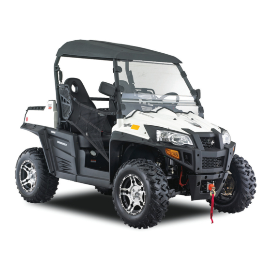
- Page 1 STRIKE 800 OWNER’S MANUAL h isu n motors .com...
- Page 2 Owner Manual INTRODUCTION Congratulations on your purchase of the HS800UTV/HS800UTV-3. This Owner’s / Operator’s manual will provide you information regarding safe operation, operational instructions, maintenance and care. Fully understanding this manual and following all of the instructions herein will provide the knowledge needed to have safe and enjoyable UTV operation.
-
Page 3: Important Manual Information
Owner Manual IMPORTANT MANUAL INFORMATION FAILURE TO FOLLOW THE WARNINGS CONTAINED IN THIS MANUAL CAN RESULT IN SERIOUS Particularly important information is distinguished in this manual by the following INJURY OR DEATH. notations: The Safety Alert Symbol means ATTENTION! YOUR SAFETY IS INVOLVED! Failure to follow WARNING instructions could result in severe injury or death to the machine operator, bystander or a person inspecting or repairing the machine. -
Page 4: Important Notice
Owner Manual IMPORTANT NOTICE Turning speed must be smaller than 30km/h. This UTV is designed and manufactured for OFF - ROAD use only. It is illegal and unsafe to operate this UTV on any public street, road or highway. This UTV complies with all applicable OFF - ROAD noise level and spark arrester laws and regulations in effect at the time of manufacture. -
Page 5: Table Of Contents
Owner Manual Location of the Warning and Switches 4-10 Specification Labels Accelerator Pedal 4-14 Brake Pedal 4-16 Safety Information Drive Select Lever 4-16 Fuel Tank Cap 4-17 Description and Vehicle Seats 4-17 Identification Moving Seat Forward and Identification Number Records Backward. - Page 6 Owner Manual Starting the Engine Coolant Warming Up Final Gear Oil Drive Select Lever Operation and Differential Gear Oil Driving In Reverse Adjustment of steering wheel Parking Throttle Pedal Throttle Free-Play Parking on a Slope Throttle Free-Play Inspection Reverse Limit Throttle Free-Play Adjustment 5-10 Vehicle Break-in Period...
- Page 7 Owner Manual Rear Axle Differential Lock 7-15 Differential Gear Oil 8-17 Riding Over Rough Terrain 7-15 Coolant 8-20 Riding in Brush or Wooded Areas Axle Boots 7-16 8-21 Encountering Obstacles on the Spark Plug Inspection 8-22 Trail 7-17 Inspection 8-23 Installation 8-23 Periodic Maintenance and...
- Page 8 Owner Manual 11-1 Fault code of Electronic Injection Rear Knuckle Upper and Lower System Pivot Lubrication 8-36 Steering Shaft Lubrication 8-37 12-1 USA EPA Emissions Limited Wheel Removal 8-39 Warranty Wheel Installation 8-39 Battery 8-40 Battery Maintenance 8-42 Fuse Replacement 8-42 Replacing Headlight Bulb 8-45...
-
Page 9: Location Of The Warning And
Location of the Warning and Safety Labels... - Page 10 Location of the Warning and Safety Labels Read and understand all of the labels on your vehicle. They contain important information for safe and proper operation of your vehicle. Never remove any labels from your vehicle. If a label becomes difficult to read or comes off, a replacement label is available from your dealer.
- Page 11 Location of the Warning and Safety Labels...
- Page 12 Location of the Warning and Safety Labels...
- Page 13 Location of the Warning and Safety Labels...
- Page 14 Location of the Warning and Safety Labels...
-
Page 15: Safety Information
Safety Information SAFETY INFORMATION This off-highway utility vehicle handles differently from other vehicles including cars and UTVs. can result if you do not follow these instructions: SEVERE INJURY OR DEATH Read this manual and all labels carefully and follow the operating procedures described. ●... - Page 16 Safety Information Never attempt jumps of other stunts. ● Always inspect your vehicle each time you use it to be sure it is in safe operating condition, ● Always follow the inspection and maintenance procedures and schedules described in this manual.
- Page 17 Safety Information Never operate the vehicle on hills that are too steep for it or for your abilities. Go straight up and ● down hills where possible. Maximum slope angle: 15°. Never operate on hills that are slippery or ones where you will not be able to see far enough ●...
- Page 18 Safety Information WARNING POTENTIAL HAZARD Improper handling of gasoline. WHAT CAN HAPPEN Gasoline can catch fire and you could be burned. HOW TO AVOID THE HAZARD Always turn off the engine when refueling. Do not refuel right after the engine has been running and is still very hot.
- Page 19 Safety Information WARNING POTENTIAL HAZARD Starting or running the engine in a closed area. WHAT CAN HAPPEN Exhaust fumes are poisonous and may cause loss of consciousness and death within a short time. HOW TO AVOID THE HAZARD Always operate your vehicle in an area with adequate ventilation.
-
Page 20: 3-1 Description And Vehicle Identification
3-1 Description and Vehicle Identification Headlights Rear shock absorber assembly Front shock absorber assembly Spark arrester Brake fluid reservoir CVT-belt case Driver seat Passenger seat belt Battery Right shoulder protection plate Relay assembly Spark plug Left shoulder protection plate Oil filter cartridge Driver seat belt Fuel tank cap Air filter element... - Page 21 Description and Vehicle Identification Steering wheel Light switch Ignition switch On-Command four-wheel-drive and differential lock switches Multi-function display gauge Auxiliary DC jack WARNING Passenger handrail Drive select lever To protect drivers and passengers’ Accelerator pedal Brake pedal arm, leg and feet, make sure the cab Cab nets.
-
Page 22: Identification Number Records
3-3 Description and Vehicle Identification Identification Number Records Vehicle Identification Number Record the Vehicle Identification Number and The Vehicle Identification Number is stamped model label information in spaces provided for into the frame. assistance when ordering spare parts from a dealer or for reference in case the vehicle is stolen. -
Page 23: Control Functions
Control Functions CONTROL FUNCTIONS Functions of the respective switch positions are as follows: Main Switch All electrical circuits are supplied with power, and the headlights and taillights illuminate when the light switch is on. OFF: All electrical circuits are switched off. The key can be removed in this position. -
Page 24: Indicator And Warning Lights
Control Functions Indicator and Warning Lights CAUTION: Do not operate the electric starter ● continuously for more than 5 seconds, or starter damage could occur. Wait at least 5 seconds between each operation of the electric starter to let it cool. Do not turn the key to the “START”... - Page 25 Control Functions This indicator light comes on when the drive Low-Range Indicator Light “L” select lever is in the “R” reverse position. This indicator light comes on when the drive select lever is in the “L” position. Coolant Temperature Warning Light “ ”...
-
Page 26: Use Of Eps System
Control Functions is out. Continuous use while the light is The Meter works together with EPS system on may cause damage to the engine. and monitors the working condition of the High beam indicator EPS system. The light being on means headlight is at high Fault codes will be displayed by fault beam mode. -
Page 27: Speedometer Unit
Control Functions Check the speedometer. If a fault Speedometer Unit indicator light of EPS system is not on, the ECU is ready use. If fault indicator light of EPS system is on, that means EPS system found a fault during the ECU self-checking process. -
Page 28: Odometer And Trip Meter Modes
Control Functions button on the left side toggles the display Speedometer unit functions: from the odometer, to the trip-meter, and a speedometer (which shows the speed) then to the hours meter; then it starts the an odometer (which shows the total cycle over. - Page 29 Control Functions kilometers per hour press the right side There are two 4WD indicators on the display button on the display. This will also change panel. The left 4WD indicator has a blinking displayed mileage from miles circle on the front axle when the grey and kilometers.
-
Page 30: Fault Code Indicator
Control Functions slippery roads or when climbing a steep hill, symbols showing in either the left or right make sure the 4WD lock indicator is on. 4WD indicators. When riding on a flat road at a comparatively high speed, adjust settings CAUTION: “2WD/UNLOCK”... -
Page 31: Fuel Level Indicator
Control Functions press the clock button, the time will be shown. Then after five seconds, the fault code returns again. Only after the fault is fixed, will the time show automatically. The description for the fault codes are shown in Chapter 11 of this manual. Fuel level indicator The fuel level display will indicate the fuel volume. -
Page 32: Switches
4-10 Control Functions Switches Light Switch “OFF/ ” Set the switch to “ ”to turn on the low beam and the taillights. Set the switch to “ ”to turn on the high beam and the taillights. Set the switch to “OFF” to turn off all lights. CAUTION: Do not use the headlights with the engine turned off for an extended period of time. - Page 33 Control Functions 4-11 Select the appropriate drive according to On-Command Four-Wheel–Drive terrain and the conditions. Differential Gear Lock Switches Only rear wheels have differential lock mechanism. Two-wheel drive, Power is supplied to the rear wheels only With the rear wheels differential gear locked, the two rear wheels turn at the same speed regardless of traction.
- Page 34 4-12 Control Functions unlocked ,the two rear wheels can turn at WARNING different speed. POTENTIAL HAZARD Changing from 2WD to 4WD or from 2WD to 2WD-Differential UNLOCK, or vice-versa while the vehicle is moving. WHAT CAN HAPPEN The vehicle handles differently in 4WD than in 2WD and in 2WD- Differential UNLOCK some...
- Page 35 Control Functions 4-13 To change from 4WD to 2WD On-Command Four-Wheel-Drive Switch stop the vehicle, and then set the switch to “2WD/4WD” “2WD”。The 4WD indicator will go out in the multi-function display. On-Command Differential Gear Lock Switch “2WD/UNLOCK” Select lever On-Command four –wheel-drive switch “2WD/4WD”...
-
Page 36: Accelerator Pedal
4-14 Control Functions To unlock the differential gear in 2WD faster you go. You may lose control and Stop vehicle, make sure have an accident if you cannot make a On-Command four-wheel-drive switch is set sharp enough turn for the speed you are to “2WD”, move the select lever to position traveling. - Page 37 Control Functions 4-15 WARNING POTENTIAL HAZARD Malfunction of the accelerator pedal. WHAT CAN HAPPEN The accelerator pedal could be hard to operate, making it difficult to speed up or slow down when you need to. This could cause an accident. HOW TO AVOID THE HAZARD Check the operation of the accelerator 1.
-
Page 38: Brake Pedal
4-16 Control Functions Brake Pedal Drive Select Lever The drive select lever is used to shift the Press the brake pedal to slow or stop the vehicle into low, high, neutral and reverse vehicle. positions. (Refer to pages 6-4—6-5 for the drive select lever operation.) 1. -
Page 39: Fuel Tank Cap
Control Functions 4-17 Fuel Tank Cap Seats Remove the fuel tank cap by turning it To remove a seat, Remove bolts M6 with counter clockwise. socket wrench, and then remove the seat. Installation is the reverse of removal. 1. Fuel tank cap 1. - Page 40 4-18 Control Functions WARNING POTENTIAL HAZARD A loose seat. WHAT CAN HAPPEN The operator could lose control or the operator or passenger could fall if the seat is loose during operation. HOW TO AVOID THE HAZARD Make sure the seat is mounted firmly. 1.Bolt (4×M6) CAUTION: To install the seat, Adjust the four bolts M6...
-
Page 41: Moving Seat Forward And Backward
Control Functions 4-19 Moving Seat Forward and Backward. Seat Belt The seat can be moved forward and This vehicle is equipped with three-point seat backward to fit the height of different drivers. belts for both the operator and passenger. Pull up the handle, then you can move the Always wear the seat belt while riding in the seat forward and backward. - Page 42 4-20 Control Functions 3. Put the lap portion of the belt low on your To wear the seat belt properly, do the hips. Push down on the buckle end of the following: belt as you pull up on the shoulder part 1.
-
Page 43: Cargo Bed
Control Functions 4-21 Cargo Bed WARNING POTENTIAL HAZARD Not wearing the seat belt. Wearing the seat belt improperly. WHAT CAN HAPPEN There is increased risk of being killed or seriously injured in an accident. HOW TO AVOID THE HAZARD 1. Cargo bed Always wear your seat belt when riding in the vehicle. - Page 44 4-22 Control Functions WARNING WARNING POTENTIAL HAZARD POTENTIAL HAZARD Overloading the cargo bed. Carrying a passenger in the cargo bed. WHAT CAN HAPPEN WHAT CAN HAPPEN Could cause changes vehicle The passenger could fall, be thrown handling which could lead to an out, or be struck by objects in the cargo accident.
-
Page 45: Front And Rear Shock Adjustment
Control Functions 4-23 Front and Rear Shock Adjustment(Option 1) The spring preload can be adjusted to suit the operating conditions. You can reduce preload for a softer ride, or increase preload frequent bottoming occurs. CAUTION: Frequent or severe bottoming can cause increased wear or damage to the vehicle. - Page 46 4-24 Control Functions Standard position: B WARNING A-Minimum(soft) POTENTIAL HAZARD E-Maximum(hard) Improper shock absorber adjustment. WHAT CAN HAPPEN Uneven adjustment can cause poor handling and loss of stability, which could lead to an accident. HOW TO AVOID THE HAZARD Always adjust the shock absorbers on the left and right side to the same setting.
- Page 47 Control Functions 4-25 Front and Rear Shock Adjustment(Option 2) WARNING ·Do not dispose of a damaged or worn out shock absorber assembly yourself. These shock absorber assemblies Take the shock absorber assembly to a contain highly pressurized nitrogen gas, HSUN dealer for any service. read understand following...
- Page 48 4-26 Control Functions · A special wrench can be obtained at a Spring preload 1. Loosen the locknut. HSUN dealer to make this adjustment. 2. Turn the spring preload adjusting nut in · The spring preload setting is determined direction ⓐ to increase the spring by measuring distance A, shown in the preload thereby...
- Page 49 Control Functions 4-27 damping, and in direction F to decrease the Spring travel setting(Front) rebound damping force and thereby soften Minimum(soft): 332mm(13.07 in) the damping. Maximum(hard): 442mm(17.40in) Spring travel setting(Rear) Minimum(soft): 402mm(15.83in) Maximum(hard): 502mm(19.76 in) 3. Tighten the locknut. NOTE: Always tighten the locknut against the adjusting nut, and then tighten it to the specified torque.
- Page 50 4-28 Control Functions Compression damping force Turn compression damping force WARNING adjusting screw (use 3.0 allen wrench) in ·Suspension components become hot direction ⓐ to increase the compression during operation. Never touch damping force and thereby harden the compression damping force adjusting damping, and in direction ⓑ...
-
Page 51: Trailer Hitch Bracket
Control Functions 4-29 The auxiliary DC jack can be used for Trailer Hitch Bracket suitable work lights, radios, etc. This vehicle is equipped with a 5 cm (2 in) The auxiliary DC jack should only be used receiver bracket for a standard trailer hitch. when the engine is running. - Page 52 4-30 Control Functions used, cover it with the cap. than the above maximum capacity. This may overload the circuit and cause the fuse to blow. If accessories are used without the engine running or with the headlights turned on, the battery will lose its charge and engine starting may become difficult.
-
Page 53: Pre Operation Checks
Pre Operation Checks Before using this vehicle, check the following points: ITEM ROUTINE PAGE Check operation, free play, fluid level and fluid leakage. ● Brakes 5-2—5-3,8-30—8-31 Fill with DOT 4 brake fluid if necessary. ● Check for proper operation, condition and free play. Parking brake ●... -
Page 54: Brakes
Pre Operation Checks Brakes WARNING Always check brake pedal travel and the brake POTENTIAL HAZARD fluid reservoir level before each use of the Failure to inspect the vehicle before vehicle. When applied, the brake pedal should operating. Failure to properly maintain feel firm. - Page 55 Pre Operation Checks adjust it. Apply the brakes firmly for one minute. If there is any leakage, have the vehicle inspected by a Check the operation of the brake pedal. dealer. should move smoothly and there should be a Brake Operation firm feeling when the brakes are applied.
-
Page 56: Fuel
Pre Operation Checks WARNING Fuel Make sure there is sufficient gasoline in the POTENTIAL HAZARD tank. Driving with improperly operating brakes. WHAT CAN HAPPEN Recommended fuel: You could lose braking ability, which Unleaded gasoline only could lead to an accident. Fuel tank capacity: HOW TO AVOID THE HAZARD 30.0L ( 6.6lmp gal, 7.93US gal) -
Page 57: Gasoline
Pre Operation Checks ([R+M] /2) of 91 or higher, or research octane number of 91 or higher. If knocking or pinging WARNING occurs, use a different brand of gasoline or POTENTIAL HAZARD premium unleaded fuel. Unleaded fuel will Improper care when refueling. give you longer spark plug life and reduced WHAT CAN HAPPEN maintenance cost. -
Page 58: Engine/Reduction Gear Box Oil
Pre Operation Checks Engine/Reduction Gear box Oil Coolant Make sure the engine/reduction gear box oil is Check the coolant level in the coolant reservoir when the engine is cold. (The coolant level will at the specified level. Add oil as necessary. vary with engine temperature.) The coolant CAUTION:... -
Page 59: Final Gear Oil
Pre Operation Checks level. Add oil as necessary. (See pages 8-15 —8-16 for details.) WARNING POTENTIAL HAZARD Recommended oil: Removing the radiator cap when the SAE 80 API GL-4 Hypoid gear oil engine and radiator are still hot. If desired, An SAE 80W90 hypoid gear oil may WHAT CAN HAPPEN be used for all conditions. -
Page 60: Adjustment Of Steering Wheel
Pre Operation Checks Adjustment of steering wheel: You can adjust the height of the steering board according to the driver’s height and driving habits。 1. Move handlebar to “vertical upper” direction and hold. 2. Adjust the steering board up and down to get it in proper position. -
Page 61: Throttle Free-Play
Pre Operation Checks WARNING Throttle Free-play If the throttle pedal has excessive play due to Failure to check or maintain proper cable stretch or mis-adjustment, it will cause a operation of the throttle system can result in delay in throttle response, especially at low an accident and lead to serious injury or engine speed. -
Page 62: Throttle Free-Play Adjustment
5-10 Pre Operation Checks 4. Replace the center cover and seat to their position Throttle Free-play Adjustment 1. Remove both seats. Remove the middle Steering Wheel Inspection cover of the engine, ( see PAGE 8-6 ) Check the steering wheel for specified free-play 2. -
Page 63: Fittings And Fasteners
Pre Operation Checks 5-11 out and retract on its own when released. The Check the operation of all switches. Have a latch plate should click securely into the buckle dealer repair as necessary for proper operation. and release when the release button is pushed firmly. -
Page 64: Tires
5-12 Pre Operation Checks Tires WARNING POTENTIAL HAZARD Operating this vehicle with improper tires, or with improper or uneven tire pressure. WHAT CAN HAPPEN Use of improper tires on this vehicle, or operation of this vehicle with improper or uneven tire pressure, may cause loss of control, increasing your risk of accident. - Page 65 Pre Operation Checks 5-13 3. Tire pressure below the minimum specified could cause the tire to dislodge from the rim under severe riding conditions. The following are minimums: Front 63kpa (0.64kgf/cm , 9psi) Rear 63kpa (0.64kgf/cm , 9psi) 4. Use no more than the following Pressures when seating the tire beads.
-
Page 66: How To Measure Tire Pressure
5-14 Pre Operation Checks How to Measure Tire Pressure Use the tire pressure gauge. Recommended Minimum Maximum pressure NOTE: 70kpa 63kpa 77kpa The tire pressure gauge is included as standard Front (0.70kgf/ cm (0.64kgf/ cm (0.77kgf/ cm equipment. Make two measurements of the 10psi) 9psi) 11psi) -
Page 67: Tire Wear Limit
Pre Operation Checks 5-15 Tire Wear Limit When the tire groove decreases to 3 mm (0.12 in) due to wear, replace the tire. a. Tire wear limit... -
Page 68: Operation
Operation Starting the Engine in Low Temperatures WARNING WARNING POTENTIAL HAZARD Operating vehicle without being POTENTIAL HAZARD familiar with all controls. Freezing control cables cold WHAT CAN HAPPEN weather. Loss of control, which could cause an WHAT CAN HAPPEN accident or injury. You could be unable to control the HOW TO AVOID THE HAZARD vehicle, which could lead to an... -
Page 69: Starting The Engine
Operation light should come on. If the neutral 2. Start the engine (see P6-2). indicator light does not come on, ask a Starting The Engine dealer to inspect the electric circuit. The engine can be started in any gear if CAUTION: ●... -
Page 70: Warming Up
Operation Continue warming up the engine until it idles smoothly before riding. is over 12V, the idle speed will be normal. If the idle speed is still high, please contact WARNING your dealer. POTENTIAL HAZARD Engine idle speed exceeds the regulated Warming Up speed. -
Page 71: Drive Select Lever Operation And Driving In Reverse
Operation idles smoothly. drive select lever along the shift guide. CAUTION: NOTE: See the “Engine break-in” section prior to Make sure that the drive select lever is operating the engine for the first time. completely shifted into position. Drive Select Lever Operation And Driving In Reverse CAUTION: Before shifting, you must stop the UTV and... - Page 72 Operation NOTE: The drive select lever cannot be shifted into or from reverse without applying the brake. 1. Bring the UTV to a complete stop and return the accelerate pedal to the closed position. 2. Apply the brake pedal. 3. Shift from neutral to reverse and vice Drive select lever versa by moving the drive select lever along the shift guide.
-
Page 73: Parking
Operation Parking the engine, the light may not come on 1. When parking, stop the engine and shift until the UTV starts moving. the drive select lever into the neutral position. 4. Check behind for people or obstacles, and 2. Push the brake pedal down, and pull the then release the brake pedal. -
Page 74: Parking On A Slope
Operation Parking on a Slope WARNING POTENTIAL HAZARD Parking on a hill or other incline. WHAT CAN HAPPEN The vehicle could roll out of control, increasing the chance of an accident. HOW TO AVOID THE HAZARD Avoid parking on hills or other inclines. 1. -
Page 75: Reverse Limit
Operation Reverse Limit There is no speed limitation in forward. For safety reasons, the speed is limited in reverse and in front diff-lock mode. engine is limited to lower RPM’s by the ECU when in Reverse or diff-lock mode. Vehicle Break-in Period The break-in period for your new UTV 1.Parking hand-bar vehicle is the first 25 hours of operation, or... -
Page 76: Engine Break-In
Operation read the following material. Because the procedures carefully. engine is brand new, you must not put an CAUTION: excessive load on it for the first several hours Excessive heat build-up during the first of running. ● During the first 25 hours, the various parts in three hours of operation will damage the engine wear and polish themselves to the close-fitted... -
Page 77: Accessories And Loading
Operation 6-10 consult a dealer. Apply only moderate braking force for the 0-10 Hours: first 50 stops. Aggressive or overly forceful Avoid continuous operation above half braking when the brake system is new could throttle. Allow a cooling off period of five to damage brake pads and rotors. - Page 78 6-11 Operation Accessories can affect the handing and are operating could affect your ability to control of your vehicle. Keep the following control the vehicle. in mind when considering an accessory or Do not mount an accessory where it could ●...
- Page 79 Operation 6-12 trailer. Keep the following points in mind: Do not exceed the maximum tongue ● weight. You can measure tongue Never exceed the weight limits shown. ● weight with a bathroom scale. Put the An overloaded vehicle can be unstable. tongue of the loaded trailer on the scale MAXIMUM LOADING LIMIT with the tongue at hitch height.
- Page 80 6-13 Operation Make sure the load does not interfere with ● controls or your ability to see where you WARNING are going. POTENTIAL HAZARD Drive more slowly than would without a ● Overloading this vehicle or carrying or load. The more weight you carry, the towing cargo improperly.
-
Page 81: Driving Your Vehicle
Your Vehicle DRIVING YOUR VEHICLE WARNING Getting To Know Your Vehicle POTENTIAL HAZARD This off-highway utility vehicle will handle Not wearing the seat belt. and maneuver differently from an ordinary Wearing the seat belt improperly. passenger car or other vehicle. WHAT CAN HAPPEN Before you begin to use your vehicle, be sure There is increased risk of being killed... - Page 82 Your Vehicle The total weight of operator, passenger, accessories, cargo, trailer tongue weight, WARNING POTENTIAL HAZARD and the vehicle itself must not exceed 2033 Carrying a passenger in the cargo bed. lbs (922Kg). WHAT CAN HAPPEN The passenger could fall or be struck by objects in the cargo bed.
- Page 83 Your Vehicle WARNING The driver and passenger must always wear POTENTIAL HAZARD a seat belt and an approved motorcycle Overloading this vehicle or carrying or helmet. Also wear eye protection and towing cargo improperly. protective clothing, including over-the-ankle WHAT CAN HAPPEN boots, gloves, a long-sleeved shirt or jacket, Could cause...
-
Page 84: Learning To Operate Your Vehicle
Your Vehicle your chances of a severe injury in the WARNING event of an accident. POTENTIAL HAZARD HOW TO AVOID THE HAZARD Operating this vehicle without wearing Always wear an approved motorcycle an approved motorcycle helmet, eye helmet that fits properly. You should protection, and protective clothing. - Page 85 Your Vehicle accelerator pedal, brakes, steering, and drive release the parking brake. Press the select lever. Drive first at slow speed and accelerator pedal slowly and smoothly. The become comfortable at that speed before centrifugal clutch will engage and you will gradually increasing your speed.
-
Page 86: Turning Your Vehicle
Your Vehicle they are in the way of the steering wheel Turning Your Vehicle spokes. The vehicle is easier to steer in two-wheel drive (2WD) than four-wheel drive (4WD). Steering takes the most effort in 4WD with the differential locked. It is possible for the vehicle to roll over or go control attempt... - Page 87 Your Vehicle reverse: 1. Always check for obstacles or people behind the vehicle. 2. Apply the accelerate pedal lightly. Never press down accelerate pedal suddenly. 3. Back slowly. 4. Apply the brakes lightly for stopping. 5. Avoid making sharp turns. Before shifting into reverse gear, always check for obstacles or people behind the Cab Nets and Shoulder Protection Plate...
-
Page 88: Braking
Your Vehicle terrain. In most cases, gradually application worn or damaged cab nets with new,, of the brakes is more effective than abrupt available from your authorized dealer allow braking, particularly on loose surfaces like component identification. Always use the cab gravel. - Page 89 Your Vehicle Maximum slope angle: 15° with full WARNING loading (300kg) POTENTIAL HAZARD Operating on excessively steep hills. WHAT CAN HAPPEN The vehicle can over turn more easily on extremely steep hills than on level surfaces or small hills. HOW TO AVOID THE HAZARD Never operate your vehicle on hills too steep for it or your abilities.
-
Page 90: Going Downhill
7-10 Your Vehicle Before climbing the hill, first be sure you are drive select lever in reverse so you can use operating in low range 4WD or, if necessary, the engine brake if necessary to slow your with 4WD. To climb a hill, you need traction, descent. - Page 91 Your Vehicle 7-11 vehicle is in low-range 4WD. On most slopes, this will let you use engine braking to WARNING help you go downhill slowly. Go as slowly POTENTIAL HAZARD as possible. If you start going too fast, Going down a hill improperly. gently apply the brakes.
-
Page 92: Crossing Through Shallow Water
7-12 Your Vehicle Crossing Through Shallow Lou Water WARNING If you must cross shallow, slow moving water POTENTIAL HAZARD up to the depth of the vehicle’s floorboards, Operating this vehicle through deep or choose your path carefully to avoid sharp fast-flowing water. - Page 93 Your Vehicle 7-13 If it’s impossible to take your vehicle to a CAUTION: dealer before starting it, follow the steps After riding your vehicle in water, be sure to outlined below. drain the trapped water by removing the 1. Move the vehicle to dry land. check hose at the bottom of the air filter case, 2.
- Page 94 7-14 Your Vehicle make sure inspect the hole without water left inside. If it is muddy water, open the CVT cap and wash the parts before reassemble. 9. Check the gearshift, release the water inside. Wash it if it is necessary. CAUTION:...
-
Page 95: Rear Axle Differential Lock
Your Vehicle 7-15 traction, because the skid process has 1. Drive select lever box check hose destroyed the soil structure. Even if you lock the differential, the rear wheels may continue to slip and will not drive the vehicle ahead. CAUTION:... -
Page 96: Riding In Brush Or Wooded Areas
7-16 Your Vehicle to the vehicle could occur. WARNING POTENTIAL HAZARD Failure extra care when operating this vehicle on unfamiliar terrain. WHAT CAN HAPPEN You can come upon hidden rocks, bumps, or holes, without enough time to react. Could result in the vehicle overturning or going out of control. -
Page 97: Encountering Obstacles On The Trail
Your Vehicle 7-17 yourself plenty of time to react to changes in for brush that might enter the vehicle as you conditions. If there is any question about pass and strike the driver or passenger. your ability to maneuver safely over the Never hold onto the enclosure so your hand obstacle, you should turn around, if the is outside the vehicle. - Page 98 7-18 Your Vehicle WARNING POTENTIAL HAZARD Improperly operating over obstacles. WHAT CAN HAPPEN Could cause loss of control or a collision. Could cause the vehicle to overturn. HOW TO AVOID THE HAZARD Before operating in a new area, check for obstacles. Use extreme caution when operating over large obstacles, such as large rocks or fallen trees.
-
Page 99: Periodic Maintenance And Adjustment
Periodic Maintenance and Adjustment Periodic Maintenance and Adjustment NOTE: Periodic inspection, adjustment If you do not have a torque wrench available lubrication will keep your vehicle in the safest during a service operation requiring one, take most efficient condition possible. your vehicle to dealer to check the torque Safety is an obligation of the vehicle owner. - Page 100 Periodic Maintenance and Adjustment WARNING WARNIN POTENTIAL HAZARD POTENTIAL HAZARD Operating this vehicle with improper Servicing an engine while it is running. modifications. WHAT CAN HAPPEN WHAT CAN HAPPEN Moving parts can catch clothing or Improper installation of accessories or parts of the body, causing injury.
-
Page 101: Periodic Maintenance Chart For The Emission Control System
Periodic Maintenance and Adjustment Periodic Maintenance Chart for the Emission Control System ● For vehicles not equipped with an odometer or hour meter, follow the month maintenance intervals. ● For vehicles equipped with an odometer or an hour meter, follow the km(mi) or hours maintenance intervals. However, keep in mind that if the vehicle isn’t used for a long period of time, the month maintenance intervals should be followed. -
Page 102: General Maintenance And Lubrication Chart
Periodic Maintenance and Adjustment General Maintenance and Lubrication Chart INITIAL EVERY Month Whichever ITEM ROUTINE 1,200 2,400 2,400 4,800 Comes first (mi) (200) (750) (1,500) (1,500) (3,000) hours Air Filter Elements ● Clean. Every 20─40 hours (Engine Intake ● Replace if necessary. (More often in wet or dusty areas.) Duct) Engine Oil... - Page 103 Periodic Maintenance and Adjustment INITIAL EVERY Month Whichever ITEM ROUTINE 1,200 2,400 2,400 4,800 Comes first (mi) (200) (750) (1,500) (1,500) (3,000) hours ● Check operation and for looseness. Replace if Steering System* damaged. ○ ○ ○ ○ ○ ● Check toe-in. Adjust if necessary Rear Upper and Lower ●...
-
Page 104: Sundry Box Cover
Periodic Maintenance and Adjustment Sundry Box Cover Engine Cover To Open/ Close To Open/ Close Unhook the hood latches, and then slowly tilt 1. Remove two seats ( see page 4-17 ) the sundry box cover up. To close, tilt cover 2. -
Page 105: Efi System
Periodic Maintenance and Adjustment EFI system An EFI engine is completely different from the engine which uses carburetor, it consist of ECU, EFI-cables, sensors, actuators and other advanced components. As the following pictures: 1. Oxygen sensor 2. Oxygen sensor threaded sleeve 3. - Page 106 Periodic Maintenance and Adjustment 1. Water temperature sensor 1. Fuel injector 2. Inlet bent pipe 1. Idle speed stepper motor 3. Intake air temperature sensor/ pressure sensor 2. Air damper degree sensor 4. Ducting dampers 3. Air damper Air damper For the purpose of adjustment of air intake volume.
-
Page 107: Efi System Inspection
Periodic Maintenance and Adjustment according to the temperature difference, Fuel injector ECU will automatically revise fuel injection Inject the fuel into the cylinder volume, to ensure the smooth operation of Intake air temperature sensor the engine all the time. Inspect engine intake temperature,... -
Page 108: Engine Oil And Oil Filter Cartridge
8-10 Periodic Maintenance and Adjustment replaced at the intervals specified in the also use the special "EFI system failure periodic maintenance and lubrication chart. diagnostic apparatus" inspection, diagnostic apparatus can provide a more To Check Engine Oil Level detailed faliure information . Diagnostic 1. -
Page 109: To Change The Engine Oil
Periodic Maintenance and Adjustment 8-11 To Change the Engine Oil (With or Without Oil Filter Cartridge Replacement) 1. Remove the console. Place an oil pan under the engine to collect the used oil, and then remove the engine oil filler cap. 2. - Page 110 8-12 Periodic Maintenance and Adjustment being replaced. O-ring of the new oil filter cartridge. 3. Remove the oil filter cartridge with an oil NOTE: filter wrench. Make sure the O-ring is seated properly. 1. Oil filter cartridge 2. Oil filter bolt NOTE: An oil filter wrench is available at a nearby 1.
- Page 111 Periodic Maintenance and Adjustment 8-13 Tightening torque: 7. Add specified amount Oil filter cartridge: recommended engine oil, and then install 17Nm (1.7m·kgf, 12 ft-lbs) the engine oil filler cap and tighten it. Recommended engine oil: See page 10-2. Oil quantity: Without oil filter cartridge replacement: 1.05L (1.67 lmp qt, 2.01 US qt) With oil filter cartridge replacement:...
- Page 112 8-14 Periodic Maintenance and Adjustment labeled “ENERGY CONSERVING II” or 3. Add sufficient engine oil higher. 4. Screw up oil inlet bolt. Make sure that no foreign material enters the crankcase. 9. Start the engine, and then let it idle for several minutes while checking it for oil leakage.
-
Page 113: Final Gear Oil
Periodic Maintenance and Adjustment 8-15 Final Gear Oil Checking the Final Gear Oil Level 1. Place the vehicle on a level surface. 2. Remove the oil filler bolt, and then check the oil level in the final gear case. 1. Oil outlet bolt Recommended engine oil: See page 10-2. -
Page 114: Changing The Final Gear Oil
8-16 Periodic Maintenance and Adjustment 3. If the oil is below the brim of the filler hole, Changing the Final Gear Oil 1. Place the vehicle on a level surface. add sufficient oil of the recommended 2. Place a container under the final gear type to raise it to the correct level. -
Page 115: Differential Gear Oil
Periodic Maintenance and Adjustment 8-17 Tightening torque: Tightening torque: Final gear oil drain bolt: Final gear oil filler bolt: 20 Nm (2.0 m-kgf, 14 ft-lbs ) 23 Nm (2.3 m-kgf, 16.3 ft-lbs) 7. Check for oil leakage. If oil leakage is 5. - Page 116 8-18 Periodic Maintenance and Adjustment 2. Install the differential gear oil filler bolt, and then tighten it to the specified torque. Tightening torque: Differential gear oil filler bolt: 23Nm (2.3 m-kgf, 16.3 ft-lbs) 1. Speed sensor 2. Correct oil level 3.
- Page 117 Periodic Maintenance and Adjustment 8-19 5. Fill the differential gear case with the recommended oil. Recommended oil: SAE 80 API GL-5 Hypoid gear oil Oil quantity: 0.1 L (0.085 lmp qt, 0.105 US qt) CAUTION: Be sure no foreign material enters the differential gear case.
-
Page 118: Coolant
8-20 Periodic Maintenance and Adjustment Coolant The coolant level should be checked before each ride. Checking the Coolant Level 1. Place the vehicle on a level surface. 2. Open the hood. (See pages 8-6 for hood opening and closing procedures.) 3. -
Page 119: Axle Boots
Periodic Maintenance and Adjustment 8-21 Total amount: Coolant reservoir capacity 1.32L (1.16 lmp qt, 1.40 US qt) (up to the maximum level mark): Coolant reservoir capacity 0.627L(0.555lmp qt, 0.663US qt) (up to the maximum level mark): 0.627 L (0.55 lmp qt, 0.65 US qt) CAUTION: Mix anti freeze with distilled water only. -
Page 120: Spark Plug Inspection
8-22 Periodic Maintenance and Adjustment If any damage is found, have them replaced Spark Plug Inspection by a dealer. Removal Remove hood (See pages 8-6) 2. Remove the spark plug cap. 3. Use the spark plug wrench in the tool kit to remove the spark plug as shown. -
Page 121: Inspection
Periodic Maintenance and Adjustment 8-23 normally. Do not attempt to diagnose such problems yourself. Instead, take the vehicle to a dealer. You should periodically remove and inspect the spark plug because heat and deposits will cause the spark plug to slowly break down and erode. - Page 122 8-24 Periodic Maintenance and Adjustment threads. 3. Install the spark plug and tighten it to the specified torque. Tightening torque: Spark plug: 17.5 Nm(1.75 m-kgf, 12.4 ft-lbs) NOTE: If a torque wrench is not available when you a. Spark plug gap are installing the spark plug, a good estimate of the correct torque is 1/4 to 1/2 turn past Spark plug gap:...
-
Page 123: Cleaning The Air Filter Elements
Periodic Maintenance and Adjustment 8-25 Cleaning the Air Filter Element 2. Remove the Engine cover. (See page 8-9 for Engine cover removal and installation NOTE: procedure.) There is a check hose at the bottom of the air 3. Remove the connecting rubber tube filter case. - Page 124 8-26 Periodic Maintenance and Adjustment frame. 1. Air filter frame 2. Sponge material 3. Element retaining plate 6. Wash the sponge material gently but thoroughly in solvent. WARNING POTENTIAL HAZARD Using low flash point solvents or gasoline to clean the sponge material. WHAT CAN HAPPEN Air filter element Low flash point solvents or gasoline...
- Page 125 Periodic Maintenance and Adjustment 8-27 CAUTION: Do not twist the sponge material when squeezing it. 8. Inspect the sponge material and replace it if damaged. 9. Thoroughly apply foam air filter oil or other quality liquid foam air filter oil (not spray type) to the sponge material.
-
Page 126: Cleaning The Spark Arrester
8-28 Periodic Maintenance and Adjustment time air filter element maintenance is Cleaning the Spark Arrester performed, check the air inlet to the air filter Be sure the exhaust pipe and muffler are case for obstructions. Check the air filter cool before cleaning the spark arrester. element rubber joint to the throttle valve and 1. - Page 127 Periodic Maintenance and Adjustment 8-29 tailpipe and inside of the tailpipe housing. Tightening torque: Tailpipe bolt: 12 Nm(1.2 m-kgf, 8.5 ft-lbs) WARNING POTENTIAL HAZARD Improper cleaning of the spark arrester. Hot exhaust system. WHAT CAN HAPPEN Could injure the eyes. Could cause burns.
-
Page 128: Valve Clearance
8-30 Periodic Maintenance and Adjustment Valve Clearance The correct valve clearance changes with use, resulting in improper fuel-air supply or engine noise. To prevent this, the valve clearance must be adjusted regularly. This adjustment however, should be left to a professional service technician. -
Page 129: Checking The Brake Fluid Level
Periodic Maintenance and Adjustment 8-31 indicator grooves, which allow you to check Checking the Brake Fluid Level the brake pad wear without having to Insufficient brake fluid may let air enter the disassemble the brake system. To check the brake system, possibly causing the brakes to brake pad wear, check the wear indicator become ineffective. -
Page 130: Brake Fluid Replacement
8-32 Periodic Maintenance and Adjustment braking performance Recommended brake fluid: DOT 4 Refill with the same type of brake fluid. Mixing fluids may result a harmful chemical reaction and lead to poor braking performance. Be careful that water does not enter the brake fluid reservoir when refilling. -
Page 131: Checking The Brake Pedal
Periodic Maintenance and Adjustment 8-33 dealer replace the following components during periodic maintenance or when they are damaged or leaking. Replace the oil seals every two years. Replace the brake hoses every four years. Checking the Brake Pedal Have a dealer check the brakes at the intervals specified... -
Page 132: Brake Light Switch Adjustment
8-34 Periodic Maintenance and Adjustment Brake Light Switch Adjustment WARNING The brake light switch, which is activated by POTENTIAL HAZARD the brake pedal, is properly adjusted when Operating with improperly serviced or the brake light comes on just before braking adjusted brakes. -
Page 133: Cable Inspection And Lubrication
Periodic Maintenance and Adjustment 8-35 Cable Inspection and Lubrication WARNING POTENTIAL HAZARD Damaged control cables. WHAT CAN HAPPEN Corrosion can result when the outer covering of control cables becomes damaged. Cables can also become 1. Brake light switch. 2. Adjusting nut frayed kinked. -
Page 134: Brake Pedal And Accelerator Pedal Lubrication
8-36 Periodic Maintenance and Adjustment ask a dealer to replace them. Recommended lubricant: Engine oil:see page 10-2 Brake Pedal and Accelerator Pedal Lubrication Lubricate the pivoting parts. Recommended lubricant: Lithium-based grease (all-purpose grease) Rear Knuckle Upper and Lower Pivot Lubrication Lubricate the knuckle upper and lower pivots with a grease gun. -
Page 135: Steering Shaft Lubrication
Periodic Maintenance and Adjustment 8-37 Recommended lubricant: Lithium-based grease (all-purpose grease) Upper universal joint steering transmission shaft Recommended lubricant: Lithium-based grease Steering Shaft Lubrication Lubricate the pivot points. - Page 136 8-38 Periodic Maintenance and Adjustment Front balance rod Lower universal joint steering transmission shaft Rear balance rod...
-
Page 137: Wheel Removal
Periodic Maintenance and Adjustment 8-39 Wheel Removal Loosen the wheel nuts. NOTE: The arrow mark on the tire must point Elevate the vehicle and place a suitable ● toward the rotating direction of the wheel. stand under the frame. Tapered nuts are used for both the front ●... -
Page 138: Battery
8-40 Periodic Maintenance and Adjustment Wheel nut torque: Front:70Nm(7.0 m-kgf, 49.7 ft-lbs) Rear:70Nm(7.0 m-kgf, 49.7 ft-lbs) Battery This vehicle is equipped with a sealed-type battery. Therefore it is not necessary to check the electrolyte or add distilled water in 1.Tapered nut the battery. - Page 139 Periodic Maintenance and Adjustment 8-41 WARNING POTENTIAL HAZARD Failure to handle batteries or battery electrolyte carefully. WHAT CAN HAPPEN You could be poisoned. You could be severely burned by the sulfuric acid in battery electrolyte. Batteries produce explosive gases. HOW TO AVOID THE HAZARD Avoid contact with skin, eyes or clothing.
-
Page 140: Battery Maintenance
8-42 Periodic Maintenance and Adjustment Battery Maintenance CAUTION: 1. When the vehicle is not used for a month or longer, remove the battery and store it special battery charger (constant in a cool, dark place. Completely voltage/ampere or constant voltage) is recharge the battery before reinstallation. - Page 141 Periodic Maintenance and Adjustment 8-43 WARNING POTENTIAL HAZARD Using an improper fuse WHAT CAN HAPPEN An improper fuse can cause damage to the electrical system, which could lead to a fire. HOW TO AVOID THE HAZARD Always use a fuse of the specified rating. Never use a material in place of the proper fuse.
- Page 142 8-44 Periodic Maintenance and Adjustment Specified Fuse: Main Fuse: 30.0A Headlight Fuse: 15.0A ECU Fuse: 15.0A Auxiliary DC Jack Fuse: 10.0A Signaling System Fuse: 10.0A 2WD/4WD Fuse 10.0A Backup Fuse: 5.0A/10.0A/15.0A Speedmeter/ECU 5.0A 1. Relay assembly 2. Backup fuse -normal open Fuse: 3.
-
Page 143: Replacing Headlight Bulb
Periodic Maintenance and Adjustment 8-45 Replacing Headlight Bulb If a headlight bulb burns out, replace it as follows. 1. Lift the hood up. (See pages 8-6 for hood opening and closing procedures.) 2. Remove the cover at the rear of the headlight by pulling it off. - Page 144 8-46 Periodic Maintenance and Adjustment Do not touch the glass part of the bulb. WARNING POTENTIAL HAZARD A headlight bulb is hot when it is on and immediately after it is turned off. WHAT CAN HAPPEN You can be burned, or a fire could start bulb touches something...
-
Page 145: Tail/Brake Light Bulb Replacement
Periodic Maintenance and Adjustment 8-47 fingerprints on the headlight bulb using a quick fasteners and bolts. cloth moistened with alcohol or thinner. 8. Install the bulb holder by pushing it in and turning it clockwise. 9. Install the bulb holder cover and the cover at the rear of the headlight. - Page 146 8-48 Periodic Maintenance and Adjustment 1. Cargo bed 2. Remove the bulb holder (together with the bulb) by turning it counter clockwise. 3. Push the defective bulb in and turn it counter clockwise to remove it from the bulb holder. 4.
-
Page 147: Troubleshooting
Periodic Maintenance and Adjustment 8-49 properly service your vehicle. Imitation 6. Install the panel by installing the quick parts may look like original parts, but they are fasteners and bolts, and then tighten the often inferior. Consequently, they have a bolts to the specified torque. -
Page 148: Check And Solution To Common Problems In The Vehicle
8-50 Periodic Maintenance and Adjustment Check and solution to Common Problems in Vehicle Here you can see some tables on the common problems which may come up when you are driving a UTV, which will help to solve these problems. To repair a UTV requires technical skills, if you cannot fix it yourself, please contact your dealer. - Page 149 Periodic Maintenance and Adjustment 8-51 : Table 2 Check and Solution of Common Problems in Brake System. Problems Solutions 1. Check if the parking brake is activated. Brake system is locked 2. Check if the brake discs are damaged. 3. Check if the calipers', or hydraulic cylinders are stuck, or if the mounting brackets of calipers are damaged.
- Page 150 8-52 Periodic Maintenance and Adjustment 1. Check if there is an equal amount of force being applied by the left and right brake calipers on the front and rear brakes. 2. Check if the brake force of front brakes has deteriorated, which might cause the rear wheels to lock up before the Vehicle pulls to the left or front wheels.
- Page 151 Periodic Maintenance and Adjustment 8-53 Table 3: Check and Solution of Common Problems in Electrical System Problems Solutions 1. Check if the headlight switch functions well. Lights don't work. 2. Check if the wires are broken. 3. Check if the lamps or bulbs are broken. 1.
- Page 152 8-54 Periodic Maintenance and Adjustment Table 4: Check and Solution of Common Problems in Running System Problems Solutions 1.Check the screws connecting steering rod to steering stem and knuckle to find out if they are loose or broken Too much movement 2.Check the ball studs on the ends of steering rod to find out if in the steering wheel they are broken...
- Page 153 Periodic Maintenance and Adjustment 8-55 3. Check the splined rear wheel hubs and spline shaft of rear Rear wheels shake wheel axles to find out if they are worn or broken. during operation. 4. Check the nuts and cotter pins on the rear wheels and axles to find out if they are loose or broken.
- Page 154 8-56 Periodic Maintenance and Adjustment Table5: Check and Solution of Common Problems in Engine System Problems Solutions 1. Check the battery voltage. Idle speed is not stable 2. Check the rectifier output voltage. 3.Check MEUI for failure 1. Check both cylinders are working properly . 2.
- Page 155 Periodic Maintenance and Adjustment 8-57 4.Check the coolant loop is mixed with air 1.Check the battery ,which if low, may cause the motor failure 2.Check the starter motor for damage 3.Check if MEUI is in working order 4.Check if the ignition loop is in working order Engine can not start 5.Check if the spark plug has carbon deposits or is burned 6.Check if the ignition signal is in working order...
- Page 156 8-58 Periodic Maintenance and Adjustment WARNING POTENTIAL HAZARD Removing the radiator cap when the engine and radiator are still hot. WHAT CAN HAPPEN You could be burned by hot fluid and steam blown out under pressure. HOW TO AVOID THE HAZARD Wait for the engine to cool before removing the radiator cap.
-
Page 157: Cleaning And Storage
Cleaning and Storage Cleaning CAUTION: Frequent, thorough cleaning of your vehicle Excessive water pressure may cause water will not only enhance its appearance but will seepage and deterioration of wheel bearings, improve its general performance and extend brakes, transmission seals and electrical the useful life of many components. - Page 158 Cleaning and Storage cloth. 6. Clean the seats with vinyl upholstery WARNING cleaner to keep the cover pliable and POTENTIAL HAZARD glossy. Operation with brakes after 7. Automotive type wax may be applied to washing. all painted and chrome plated surfaces. WHAT CAN HAPPEN Avoid combination...
-
Page 159: Storage
Cleaning and Storage Storage Specified amount: Long term storage (60 days or more) of your 1 oz of stabilizer to each gallon of fuel (or vehicle will require some preventive 7.5 ml of stabilizer to each liter of fuel) procedures to guard against deterioration. After thoroughly cleaning... - Page 160 Cleaning and Storage 6. Tie a plastic bag over the exhaust pipe outlet to prevent moisture from entering. 7. If storing in a humid or salty atmosphere, coat all exposed metal surfaces with a light film of oil. Do not apply oil to any rubber parts or the seat covers.
- Page 161 Specification 10-1 Model HS800UTV/HS800UTV-3 Dimensions: Overall length 2700mm (106.3 in) Overall width 1360mm (53.5 in) for HS800UTV Overall width 1520mm (59.8 in) for HS800UTV-3 Overall height 1840mm (72.4 in) Seat height 425mm (16.7 in) Wheelbase 1940mm (76.4 in) Ground clearance 260 mm (10.2 in) Minimum turning radius 5000 mm (196.9 in)
-
Page 162: Specifications
10-2 Specifications Model HS800UTV/HS800UTV-3 Engine oil: Type API service SG type or higher, JASO standard MA Recommended engine oil classification CAUTION: In order to prevent clutch slippage (since the engine oil also lubricates the clutch), do not mix any chemical additives. - Page 163 Specification 10-3 Model HS800UTV/HS800UTV-3 Final gear case oil: Type SAE80 API GL-4 Hypoid gear oil Quantity: 0.40L (0.35 lmp qt, 0.41 US qt) Differential gear case oil: Type SAE80 API GL-5 Hypoid gear oil Quantity: 0.10L (0.08 lmp qt, 0.1 US qt) Radiator capacity (including all routes): 2.50L (2.20 lmp qt, 2.64 US qt) Air filter:...
- Page 164 10-4 Specifications Model HS800UTV/HS800UTV-3 Transmission: Primary reduction system CVT-belt Secondary reduction system Shaft drive CVT reduction ratio 0.68-2.7 Transmission type CVT-belt automatic Operation Right hand operation Reverse gear 5.45 Sub transmission ratio 1.172 High 2.150 Chassis: Frame type Steel tube frame Caster angle 5.0°...
-
Page 165: System
Specification 10-5 Model HS800UTV/HS800UTV-3 Brakes: System Front and rear unified Type Front Dual disc brake Rear Dual disc brake Operation Foot operation Suspension: Front/ Rear suspension Double wishbone Shock absorber: Front shock absorber Coil spring/oil damper for HS800UTV Coil spring/oil or airbag damping for HS800UTV-3 Rear shock absorber Coil spring/oil damper for HS800UTV Coil spring/oil or airbag damping for HS800UTV-3... - Page 166 10-6 Specifications Model HS800UTV/HS800UTV-3 Bulb voltage, wattage × quantity: Headlight 12V35.0W/35.0W × 2 Tail/brake light 12V5.0W/21.0W × 2 Front/Rear turning light 12V10.0W/10.0W × 2 License light 12V3.0W Indicator lights: Neutral indicator light Reverse indicator light Coolant temperature warning light Parking brake indicator light Diff-lock indicator On-Command differential gear lock indicator light High-range indicator light...
-
Page 167: Fault Code Of Electronic Injection
Fault Code of Electronic Injection System 11-1 Fault Code of Electronic Injection System DTC Description Related Calibration Number P0107 MAP Circuit Low Voltage or Open KsDGDM_MAP_ShortLow P0108 MAP Circuit High Voltage KsDGDM_MAP_ShortHigh P0112 IAT Circuit Low Voltage KsDGDM_IAT_ShortLow P0113 IAT Circuit High Voltage or Open KsDGDM_IAT_ShortHigh Coolant/Oil Temperature Sensor Circuit P0117... - Page 168 Fault Code of Electronic Injection System 11-2 P0132 O2S 1 Circuit High Voltage KsDGDM_O2_1_ShortHigh P0031 O2S Heater Circuit High Voltage KsDGDM_O2_HeaterShortHigh P0032 O2S Heater Circuit Low Voltage KsDGDM_O2_HeaterShortLow P0201 Injector 1 Circuit Malfunction KsDGDM_INJ_CYL_A_Fault P0202 Injector 2 Circuit Malfunction KsDGDM_INJ_CYL_B_Fault P0230 FPR Coil Circuit Low Voltage or Open KsDGDM_FPP_CircuitShortLow...
- Page 169 Fault Code of Electronic Injection System 11-3 P0563 System Voltage High KsDGDM_SysVoltHigh 1379 P0650 MIL Circuit Malfunction KsDGDM_MIL_Circuit 1616 P1693 Tachometer Circuit Low Voltage KsDGDM_TAC_Circuit_Low 1693 5779 P1694 Tachometer Circuit High Voltage KsDGDM_TAC_Circuit_High 1694 5780 P0137 O2S 2 Circuit Low Voltage KsDGDM_O2_2_ShortLow P0138 O2S 2 Circuit High Voltage...
- Page 170 Where a warrantable condition exists, HISUN will repair your vehicle at no cost to you, including diagnosis, parts and labor. If an emission-related part on your vehicle is defective, the part will be repaired or replaced by HISUN. This is your EMISSION CONTROL SYSTEM WARRANTY.
- Page 171 Emission Control System Warranty Statement 12-2 As the vehicle owner, you should be aware that HISUN may deny your warranty coverage if your vehicle or a part has failed due to abuse, neglect, improper maintenance or unapproved modifications. If you use your vehicle in any type of competitive event, this warranty is immediately and completely void.
- Page 172 HISUN brand vehicle for any purpose. Some states do not allow the exclusion or limitation of any incidental or consequential damages, so the above limitations may not apply to you.
- Page 173 VI. ADDITIONAL INFORMATION. Any replacement part that is equivalent in performance and durability may be used in the performance of any maintenance or repairs by the owner. However, HISUN is not liable for these parts. The owner is responsible for the performance of all required maintenance.
- Page 174 Owner Manual...
- Page 175 STRIKE 800 OWNER’S MANUAL For your nearest HISUN dealer, call 1-(972) 446-0760 or visit hisunmotors.com. HISUN Motors Corp USA | McKinney, TX 75069 © HISUN 2015. All rights reserved. Rev 07021501...
Need help?
Do you have a question about the STRIKE 800 and is the answer not in the manual?
Questions and answers