Advertisement
Quick Links
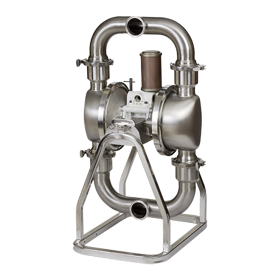
Repair/Parts
Verder
Verder HI HI HI - - - CLEAN
Verder
CLEAN Diaphragm
CLEAN
Pump, Model
Model VA
Pump,
Pump,
Model
For transfer
transfer of of of fluids
fluids in in in sanitary
For
For
transfer
fluids
hazardous (classified)
(classified) locations
hazardous
hazardous
(classified)
For
For
For professional
professional use
professional
use only.
use
Important Safety
Safety Instructions
Important
Important
Safety
Read all warnings and instructions in this manual and in your
Operation manual before using this equipment. Save
instructions.
instructions.
instructions.
8 bar (0.8 MPa, 120 psi) Maximum Fluid
Working Pressure
8 bar (0.8 MPa, 120 psi) Maximum Ait
Input Pressure
See page 6 for approvals.
Diaphragm
Diaphragm
VA - - - 2H40
2H40
VA
2H40
sanitary applications.
applications. Not
sanitary
applications.
locations unless
unless otherwise
otherwise stated.
locations
unless
otherwise
only.
only.
Instructions
Instructions
Not approved
approved for
for use
use in in in explosive
Not
approved
for
use
stated. See
See Approvals
Approvals page
stated.
See
Approvals
Save these
these
Save
these
812.0064
explosive atmospheres
atmospheres or or or
explosive
atmospheres
page for
for more
more information.
information.
page
for
more
information.
Rev.A
EN
Advertisement

Related Manuals for VERDER HI-CLEAN VA-2H40


Summary of Contents for VERDER HI-CLEAN VA-2H40
- Page 1 Repair/Parts Verder Verder Verder HI HI HI - - - CLEAN CLEAN Diaphragm CLEAN Diaphragm Diaphragm Pump, Model Model VA VA - - - 2H40 2H40 Pump, Pump, Model 2H40 812.0064 Rev.A For transfer transfer of of of fluids fluids in in in sanitary sanitary applications.
-
Page 2: Table Of Contents
Technical Data ........... 29 Air Valve Repair........... 9 Check Valve Repair ........12 Customer Services/Guarantee......31 Related Manuals Manuals Related Related Manuals Manual Manual Number Manual Number Number Title Title Title 812.0061 Verder HI-CLEAN Diaphragm Pumps, Operation 812.0254 Leak Detection System, Instructions/Parts 812.0064... -
Page 3: Warnings
Warnings Warnings Warnings Warnings The following warnings are for the setup, use, grounding, maintenance, and repair of this equipment. The exclamation point symbol alerts you to a general warning and the hazard symbols refer to procedure-specific risks. When these symbols appear in the body of this manual or on warning labels, refer back to these Warnings. - Page 4 Warnings WARNING EQUIPMENT EQUIPMENT EQUIPMENT MISUSE MISUSE HAZARD MISUSE HAZARD HAZARD Misuse can cause death or serious injury. • Do not operate the unit when fatigued or under the influence of drugs or alcohol. • Do not exceed the maximum working pressure or temperature rating of the lowest rated system component.
- Page 5 Configuration Number Matrix Configuration Number Number Matrix Matrix Configuration Configuration Number Matrix Check the identification plate (ID) for the Configuration Number of your pump. Use the following matrix to define the components of your pump. When you receive your pump, record the 8 character part number found on the shipping box (e.g., 811.0018): _____________...
-
Page 6: Configuration Number Matrix
Configuration Number Matrix Approvals Approvals Approvals II 2 GD Except for 3-A pumps, all pumps are approved to: Ex h IIA T6...T3 Gb Ex h IIIB T160°C Db Diaphragm materials coded EO, TO, or combined with flapper or ball checks comply EC 1935/2004 with: Diaphragm materials coded... - Page 7 Troubleshooting Troubleshooting Troubleshooting Troubleshooting • Follow the Pressure Relief Procedure, page 9 • Check all possible problems and causes before before checking or servicing the equipment. disassembly. Problem Problem Problem Cause Cause Cause Solution Solution Solution Pump cycles at stall or Worn checks or seats.
- Page 8 Troubleshooting Problem Cause Solution Problem Problem Cause Cause Solution Solution Fluid in exhaust air. Diaphragm ruptured. Replace. See standard or overmolded diaphragm repair procedure. Loose diaphragm plate. Tighten or replace. See standard or overmolded diaphragm repair procedure. Pump exhausts excessive Worn air valve block, plate, pilot Repair or replace.
- Page 9 Repair Repair Repair Repair Pressure Relief Relief Procedure Procedure Pressure Pressure Relief Procedure 1. Follow the Pressure Relief Procedure, page 9 2. With a Torx (T20) screwdriver or 7 mm (9/32 in.) Follow the Pressure Relief Procedure socket wrench, remove the six screws (107), air whenever you see this symbol.
- Page 10 Repair 5. Inspect the valve plate (110) in place. If 6. Inspect the bearings (113, 115) in place. See damaged, use a Torx (T20) screwdriver or 7 mm Parts, page 22. The bearings are tapered and, (9/32) in.) socket wrench to remove the three if damaged, must be removed from the outside.
- Page 11 Repair Reassemble Reassemble Reassemble Air Air Valve Valve Valve 6. Grease the lower face of the pilot block (116) and install so its tabs snap into the grooves on the ends of the pilot pins (112). NOTE: NOTE: If repairs involve removing NOTE: fluid covers, perform the steps in Reassemble the Overmolded Diaphragms, page...
- Page 12 Repair Check Valve Valve Repair Repair Check Check Valve Repair 4. Remove remaining clamps (23), manifolds (17), gaskets (18), and check valves (19). NOTE: NOTE: NOTE: Kits are available for new check valve flappers, or check valve balls in a range of materials. Gasket kits also are available.
- Page 13 Repair Disassemble Disassemble Disassemble Flapper Flapper Check Flapper Check Valves Check Valves Valves 4. Remove remaining clamps (23), manifolds (16 and 17), gaskets (18), and check valves (8). 1. Follow the Pressure Relief Procedure, page 9 Disconnect all fluid and air lines. 2.
- Page 14 Repair Standard Diaphragm Diaphragm Repair Repair Standard Standard Diaphragm Repair Tools Tools Tools Required: Required: Required: 5. Disassemble the free diaphragm assembly. • Torque wrench 6. Remove plate (12) with bolt (14) installed, diaphragm (10), backer (11) if present, and plate •...
- Page 15 Repair Reassemble Reassemble Reassemble the the Standard Standard Diaphragms Standard Diaphragms Diaphragms 3. Screw assembled diaphragm assembly into shaft NOTICE NOTICE NOTICE (24) and hand tighten. After reassembly, allow the thread locker to cure 4. Grease the length of the diaphragm shaft (24), for 12 hours, or per manufacturer’s instructions, and slide it through the housing (101).
-
Page 16: Overmolded Diaphragm Repair
Repair Overmolded Diaphragm Diaphragm Repair Repair Overmolded Overmolded Diaphragm Repair Tools Tools Tools Required: Required: Required: 6. Pull the opposite diaphragm assembly and shaft (24) out of the center housing (101). Hold the • Torque wrench shaft flats with a 19 mm open end wrench and remove the diaphragm and air side plate from •... -
Page 17: Pressure Relief Procedure
Repair Reassemble Reassemble Reassemble the the Overmolded Overmolded Diaphragms Overmolded Diaphragms Diaphragms 5. Assemble the other diaphragm assembly to the NOTICE NOTICE NOTICE shaft as explained in step 2. After reassembly, allow the thread locker to cure 6. Grip both diaphragms securely around their outer for 12 hours, or per manufacturer’s instructions, edge and rotate clockwise until bottomed on the prior to operating the pump. - Page 18 Repair Reinstall the gasket (C) and the air valve cover (B). Torque all bolts according to instructions in your pump manual. 8. Reassemble the ball check valves and manifolds as explained in Check Valve Repair, page 812.0064...
-
Page 19: Air Valve Repair
Repair Center Section Section Repair Repair Center Center Section Repair Tools Tools Required: Tools Required: Required: 6. Use a 10 mm socket wrench to remove the screws (104) holding the air covers (103) to the • Torque wrench center housing (101). •... - Page 20 Repair Reassemble Reassemble Reassemble the the Center Center Center Section Section Section 1. Install the shaft u-cups (106) so the lips face 5. Align the air cover (103) so the pilot pin (112) fits of the housing. in the middle hole (M) of the three small holes near the center of the cover.
- Page 21 Repair Leak Detectors Detectors Leak Leak Detectors Leak detectors are sensors that are mounted in the 6. To install the leak detector to the pump: air covers of the pump to monitor for fluid leakage a. If the leak detector needs to be installed in caused by a diaphragm rupture.
- Page 22 Parts Parts Parts Parts Ball Check pump shown 812.0064...
- Page 23 Parts Flapper Check pump shown 812.0064...
- Page 24 Parts Parts/Kits Quick Quick Reference Reference Parts/Kits Parts/Kits Quick Reference Use this table as a quick reference for parts/kits. Go to the pages indicated in the table for a full description of kit contents. Description Qty. Qty. Qty. Description Qty. Qty.
- Page 25 Parts Center Section Section Center Center Section Sample Configuration Number: Pump Pump Wetted Seats Balls Diaphragms Connections Options Certifications Model Size Parts Section VA-2H S S S Part Part Part Description Description Description Part Part Part Description Description Description — — — 108†...
- Page 26 Parts Diaphragms Diaphragms Diaphragms Sample Configuration Number: Pump Pump Wetted Seats Balls Diaphragms Connections Options Certifications Model Size Parts Section VA-2H Bolt- - - Through Through Diaphragm Diaphragm Kits Kits Overmolded Diaphragm Diaphragm Kits Kits Bolt Bolt Through Diaphragm Kits Overmolded Overmolded Diaphragm...
- Page 27 Parts Fluid Section Section Repair Repair Kits Kits Fluid Section Section Repair Repair Kits Kits Fluid Fluid Section Repair Kits Fluid Fluid Section Repair Kits Description Description Description Description Qty. Qty. Qty. Description Description Qty. Qty. Qty. 812.0185 VA-2H40X --,FL,EO,EO 812.0198 VA-2H40X/Y --,TF,EO,EP 812.0186...
- Page 28 Parts Frames Frames Frames 819.0582 shown; includes items 2 & 3 Description Qty. Ref. Description Description Qty. Qty. Ref. Ref. 203† SCREW, 3/8–16 unc 204† WASHER, flat 205† BUSHING 206† NUT, acorn 207* PIN, quick release 208* RETAINER † Included in hinge repair kit 819.0583. * Included in quick release pin kit 819.0584.
-
Page 29: Technical Data
Technical Data Technical Data Data Technical Technical Data Verder HI HI HI- - - CLEAN CLEAN Diaphragm Diaphragm Pump, Pump, Model Model VA VA- - - 2H40 2H40 Verder Verder CLEAN Diaphragm Pump, Model 2H40 Metric Metric Metric Maximum fluid working pressure 120 psi 0.8 MPa, 8 bar... - Page 30 Technical Data Fluid Temperature Temperature Range Range Fluid Fluid Temperature Range NOTICE NOTICE NOTICE Temperature limits are based on mechanical stress only. Certain chemicals will further limit the fluid temperature range. Stay within the temperature range of the most-restricted wetted component. Operating at a fluid temperature that is too high or too low for the components of your pump may cause equipment damage.
-
Page 31: Customer Services/Guarantee
(rental use excluded) for two years after purchase date. This warranty does not cover failure of parts or components due to normal wear, damage or failure which in the judgement of VERDER arises from misuse. Parts determined by VERDER to be defective in material or workmanship will be repaired or replaced. - Page 32 Austria Austria Belgium Belgium China China Verder Austria Verder nv Verder Shanghai Instruments and Equipment Co., Ltd Eitnergasse 21/Top 8 Kontichsesteenweg 17 Building 8 Fuhai Business Park No. 299 A-1230 Wien B–2630 Aartselaar Bisheng Road, Zhangjiang Hiteck Park AUSTRIA BELGIUM...
Need help?
Do you have a question about the HI-CLEAN VA-2H40 and is the answer not in the manual?
Questions and answers