Table of Contents
Advertisement
Quick Links
Operation
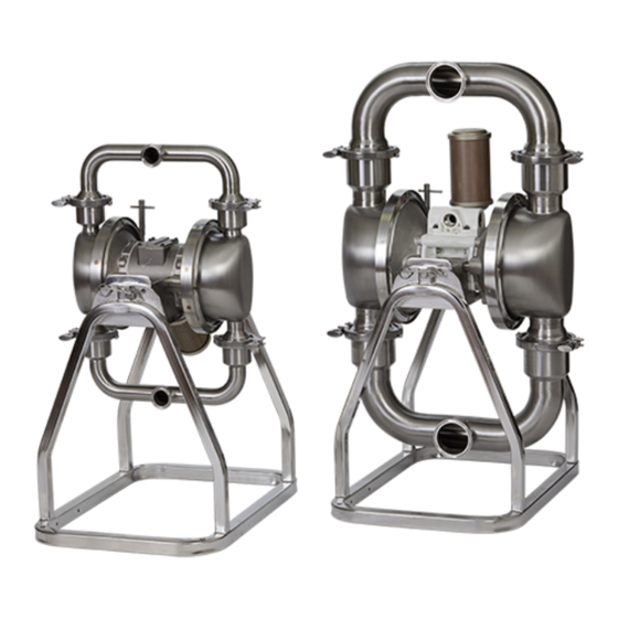
Verder HI-CLEAN
Diaphragm Pumps
Models VA-2H25, VA-2H40, VA-2H52, VA-2H53, VA-2H54
For transfer of fluids in sanitary applications. Not approved for use in explosive
atmospheres or hazardous (classified) locations unless otherwise stated. See Approvals
page for more information. For professional use only.
8 bar (0.8 MPa, 120 psi) Maximum Fluid Working Pressure
8 bar (0.8 MPa, 120 psi) Maximum Air Input Pressure
Important Safety Instructions.
Read all warnings and instructions in
this manual before using the
equipment. Save these instructions.
812.0061
Rev. A
EN
Advertisement
Table of Contents

Related Manuals for VERDER HI-CLEAN VA-2H25


Summary of Contents for VERDER HI-CLEAN VA-2H25
- Page 1 Operation Verder HI-CLEAN Diaphragm Pumps 812.0061 Models VA-2H25, VA-2H40, VA-2H52, VA-2H53, VA-2H54 Rev. A For transfer of fluids in sanitary applications. Not approved for use in explosive atmospheres or hazardous (classified) locations unless otherwise stated. See Approvals page for more information. For professional use only.
-
Page 2: Table Of Contents
Tighten Connections ..... 14 Related Manuals Manual in Description English 812.0063 Verder HI-CLEAN Diaphragm Pump, Model VA-2H25, Repair/Parts 812.0064 Verder HI-CLEAN Diaphragm Pump, Model VA-2H40, Repair/Parts 812.0065 Verder HI-CLEAN Diaphragm Pumps, Models VA-2H52, VA-2H53, VA-2H54, Repair/Parts 812.0061... -
Page 3: Warnings
Warnings Warnings The following warnings are for the setup, use, grounding, maintenance, and repair of this equipment. The exclamation point symbol alerts you to a general warning and the hazard symbol refers to procedure-specific risk. When these symbols appear in the body of this manual, refer back to these warnings. Additional, product-specific warnings may be found throughout the body of this manual where applicable. - Page 4 Warnings WARNING EQUIPMENT MISUSE HAZARD Misuse can cause death or serious injury. • Do not operate the unit when fatigued or under the influence of drugs or alcohol. • Do not exceed the maximum working pressure or temperature rating of the lowest rated system component.
-
Page 5: Configuration Number Matrix
Configuration Number Matrix Configuration Number Matrix Check the identification plate (ID) for the Configuration Number of your pump. Use the following matrix to define the components of your pump. When you receive your pump, record the 8 character part number found on the shipping box (e.g., 811.0018): _____________ Also record the configuration number on the pump ID plate to assist you when ordering replacement parts:... -
Page 6: Material Temperature Range
Configuration Number Matrix Approvals II 2 GD Except for 3-A pumps, all Ex h IIA T6...T3 Gb pumps are approved to: Ex h IIIB T160°C Db ATEX T-code rating is dependent on the temperature of the fluid being Diaphragm materials coded pumped. -
Page 7: Installation
The equipment must be grounded to reduce the risk • Always use genuine Verder parts and accessories. of static sparking. Static sparking can cause fumes to ignite or explode. Grounding provides an escape wire •... -
Page 8: Stand And Mounting
Installation Stand and Mounting Air Line The pump may be very heavy (see Technical Data A bleed-type master air valve (C) is required in the for specific weights). If the pump must be moved, system to relieve air trapped between this valve and follow the Pressure Relief Procedure on page 12 the pump. -
Page 9: Fluid Suction And Outlet Lines
Viscous liquids are more difficult to pump and more prone to cavitation. Verder recommends taking all of the above factors into account in system design. To maintain pump efficiency, supply only enough air to the pump to achieve the required flow. -
Page 10: Typical Installation
Installation Typical Installation Key: Master air valve (for accessories) Air regulator (required, not supplied) Bleed-type master air valve (for pump) (required, not supplied) Air supply line Air line coupler 1/2 npt (f) pump air inlet Flexible fluid outlet line Flexible fluid suction line Fluid shutoff valve (required, not supplied) Fluid drain valve (required, not... -
Page 11: Air Exhaust Ventilation
Installation Air Exhaust Ventilation NOTE: The air exhaust port is 3/4 npt(f). Do not restrict the air exhaust port. Excessive exhaust restriction can reduce pump performance. To provide a remote exhaust: Be sure the system is properly ventilated for your type 1. -
Page 12: Operation
Operation Operation Pressure Relief Procedure Sanitize the Pump Before First Follow the Pressure Relief Procedure when- ever you see this symbol. NOTE: The pump was built and tested using a food grade lubricant. This equipment stays pressurized until pressure is Properly sanitize the pump before first use. -
Page 13: Start And Adjust The Pump
Operation Start and Adjust the Pump 8. To prime the pump, slowly increase air pressure with the air regulator (B) until the pump starts to cycle. Do not exceed the maximum operating air 1. Confirm that the pump is properly grounded. See pressure as listed in the Technical Data, pages 17 Grounding, page 7. -
Page 14: Maintenance
Maintenance Maintenance Lubrication 5. Remove the suction line from the sanitizing solution and drain pump. The pump is lubricated at the factory. It is designed to require no further lubrication for the life of the pump. Routine Cleaning of Product There is no need to add an inline lubricator under Contact Section of Pump normal operating conditions. -
Page 15: Va-2H25 Specifications
VA-2H25 Specifications VA-2H25 Specifications VA-2H25 Dimensions Ø 10 mm (0.40 in.) A 49.0 cm (19.3 in.) E 39.9 cm (15.7 in.) B 34.8 cm (13.7 in.) F 31.2 cm (12.3 in.) C 26.7 cm (10.5 in.) G 21.6 cm (8.5 in.) D 6.6 cm (2.6 in.) 812.0061... -
Page 16: Va-2H25 Performance Chart
VA-2H25 Specifications VA-2H25 Performance Chart (140, 0.97) (9.7, 0.97) (120, 0.83) (8.3, 0.83) (100, 0.69) (6.9, 0.69) (80, 0.55) (5.5, 0.55) (60, 0.41) (4.1, 0.41) (40, 0.28) (2.8, 0.28) (20, 0.14) (1.4, 0.14) (25) (35) (40) (45) (10) (15) (20) (30) (19) (38) -
Page 17: Va-2H25 Technical Data
VA-2H25 Specifications VA-2H25 Technical Data 812.0061... -
Page 18: Va-2H40 Specifications
VA-2H40 Specifications VA-2H40 Specifications VA-2H40 Dimensions Ø 11 mm (0.43 in.) A 82.8 cm (32.6 in.) E 53.3 cm (21.0 in.) B 43.2 cm (17.0 in.) F 60.5 cm (23.8 in.) C 43.9 cm (17.3 in.) J 36.8 cm (14.5 in.) D 26.9 cm (10.6 in.) K 53.3 cm (21.0 in.) 812.0061... -
Page 19: Va-2H40 Performance Charts
VA-2H40 Specifications VA-2H40 Performance Charts Ball Check pump (140, 0.97) (9.7, 0.97) (120, 0.83) (8.3, 0.83) (100, 0.69) (6.9, 0.69) (80, 0.55) (5.5, 0.55) (60, 0.41) (4.1, 0.41) (40, 0.28) (2.8, 0.28) (20, 0.14) (1.4, 0.14) (80) (60) (100) (20) (40) (120) (76) - Page 20 VA-2H40 Specifications Flapper Check pump (140, 0.97) (9.7, 0.97) (120, 0.83) (8.3, 0.83) (100, 0.69) (6.9, 0.69) (80, 0.55) (5.5, 0.55) (60, 0.41) (4.1, 0.41) (40, 0.28) (2.8, 0.28) (20, 0.14) (1.4, 0.14) (10) (30) (20) (50) (70) (40) (60) (90) (38) (76)
-
Page 21: Va-2H40 Technical Data
VA-2H40 Specifications VA-2H40 Technical Data 812.0061... -
Page 22: Va-2H52 Specifications
VA-2H52 Specifications VA-2H52 Specifications VA-2H52 Dimensions Ø 11 mm (0.43 in.) A 90.7 cm (35.7 in.) E 68.6 cm (27.0 in.) B 49.0 cm (19.3 in.) F 60.5 cm (23.8 in.) C 43.9 cm (17.3 in.) J 36.8 cm (14.5 in.) D 19.1 cm (7.5 in.) K 53.3 cm (21.0 in.) 812.0061... -
Page 23: Va-2H52 Performance Chart
VA-2H52 Specifications VA-2H52 Performance Chart (140, 0.97) (9.7, 0.97) (120, 0.83) (8.3, 0.83) (100, 0.69) (6.9, 0.69) (80, 0.55) (5.5, 0.55) (60, 0.41) (4.1, 0.41) (40, 0.28) (2.8, 0.28) (20, 0.14) (1.4, 0.14) (40) (60) (80) (100) (140) (160) (180) (200) (20) (120) -
Page 24: Va-2H53 Specifications
VA-2H53 Specifications VA-2H53 Specifications Vertical VA-2H53 Dimensions Ø 11 mm (0.43 in.) A 100.3 cm (39.5 in.) B 52.1 cm (20.5 in.) C 43.9 cm (17.3 in.) D 11.4 cm (4.5 in.) E 84.3 cm (33.2 in.) F 60.5 cm (23.8 in.) J 36.8 cm (14.5 in.) K 53.3 cm (21.0 in.) 812.0061... -
Page 25: Horizontal Va-2H53 Dimensions
VA-2H53 Specifications Horizontal VA-2H53 Dimensions Ø 0.53 in. (13.5 mm) G 50.5 cm (19.9 in.) L 138.4 cm (54.5 in.) H 56.9 cm (22.4 in.) L2 58.4 cm (23.0 in.) J 35.6 cm (14.0 in.) M 35.1 cm (13.8 in.) K 38.6 cm (15.2 in.) N 31.0 cm (12.2 in.) 812.0061... -
Page 26: Va-2H53 Performance Chart
VA-2H53 Specifications VA-2H53 Performance Chart (140, 0.97) (9.7, 0.97) (120, 0.83) (8.3, 0.83) (100, 0.69) (6.9, 0.69) (80, 0.55) (5.5, 0.55) (60, 0.41) (4.1, 0.41) (40, 0.28) (2.8, 0.28) (20, 0.14) (1.4, 0.14) (80) (20) (40) (60) (100) (120) (140) (76) (151) (227) -
Page 27: Va-2H54 Specifications
VA-2H54 Specifications VA-2H54 Specifications Vertical VA-2H54 Dimensions Ø 13.5 mm (0.53 in.) A 116.6 cm (45.9 in.) B 58.7 cm (23.1 in.) C 29.5 cm (11.6 in.) D 11.4 cm (4.5 in.) E 99.1 cm (39.0 in.) F 53.8 cm (21.2 in.) G 40.6 cm (16.0 in.) 812.0061... -
Page 28: Horizontal Va-2H54 Dimensions
VA-2H54 Specifications Horizontal VA-2H54 Dimensions Ø 0.53 in. (13.5 mm) G 50.5 cm (19.9 in.) L 148.6 cm (58.5 in.) H 62.0 cm (24.4 in.) L2 60.2 cm (23.7 in.) J 35.6 cm (14.0 in.) M 35.1 cm (13.8 in.) K 40.6 cm (16.0 in.) N 31.0 cm (12.2 in.) 812.0061... -
Page 29: Va-2H54 Performance Chart
VA-2H54 Specifications VA-2H54 Performance Chart (9.7, 0.97) (140, 0.97) (8.3, 0.83) (120, 0.83) (6.9, 0.69) (100, 0.69) (5.5, 0.55) (80, 0.55) (60, 0.41) (4.1, 0.41) (40, 0.28) (2.8, 0.28) (20, 0.14) (1.4, 0.14) (10) (20) (30) (40) (50) (60) (70) (38) (76) (114) -
Page 30: Va-2H52, Va-2H53, Va-2H54 Technical Data
VA-2H54 Specifications VA-2H52, VA-2H53, VA-2H54 Technical Data 812.0061... - Page 31 All VERDER pumps are warranted to the original user against defects in workmanship or materials under normal use (rental use excluded) for two years after purchase date. This warranty does not cover failure of parts or components due to normal wear, damage or failure which in the judgement of VERDER arises from misuse.
- Page 32 VA-2H54 Specifications Austria Belgium China Verder Austria Verder nv Verder Shanghai Instruments and Equipment Co., Ltd Eitnergasse 21/Top 8 Kontichsesteenweg 17 Building 8 Fuhai Business Park No. 299 A-1230 Wien B–2630 Aartselaar Bisheng Road, Zhangjiang Hiteck Park AUSTRIA BELGIUM Shanghai 201204...
Need help?
Do you have a question about the HI-CLEAN VA-2H25 and is the answer not in the manual?
Questions and answers