
Related Manuals for Phytec phyCORE-OMAP44 Series


Summary of Contents for Phytec phyCORE-OMAP44 Series
- Page 1 Hardware Manual Document No.: L-760e_1 SOM Prod. No.: PCM-049-xxx SOM PCB. No.: 1347.1 CB Prod. No.: PCM-959 CB PCB. No.: 1348.2 Edition March 2012 A product of a PHYTEC Technology Holding company...
- Page 2 PHYTEC Messtechnik GmbH reserves the right to alter the informa- tion contained herein without prior notification and accepts no responsibility for any damages which might result.
-
Page 3: Table Of Contents
1.6.3.2 EEPROM Write Protection Control (J5) ......45 1.6.4Memory Model...............46 1.7 SD / MMC Card Interfaces..............47 1.8 Serial Interfaces ................49 1.8.1Universal Asynchronous Interface ..........50 1.8.2USB OTG Interface ..............51 1.8.3USB Host Transceiver (U8) ............51 1.8.4Full-Speed IC USB Host interface..........52 1.8.5Ethernet Interface..............52 L-760e_1 © PHYTEC Messtechnik GmbH 2012... - Page 4 1.14 User LEDs ..................71 1.15 Technical Specifications ..............73 1.16 Hints for Integrating and Handling the phyCORE-OMAP44xx....75 1.16.1Integrating the phyCORE-OMAP44xx ........75 1.16.2Handling the phyCORE-OMAP44xx ........... 75 1.17 Component Placement Diagram ............77 © PHYTEC Messtechnik GmbH 2012 L-760e_1...
- Page 5 2.1.3.10Audio Connectivity (X5, X14, X15, X17) ......124 2.1.3.11I2C Connectivity ............126 2.1.3.12SPI Connectivity ............129 2.1.3.13User programmable GPIOs .......... 130 2.1.3.14User programmable LEDs..........132 2.1.3.15Extension Connectors (X18, X19) ......... 133 2.1.3.16Secure Digital Memory / MultiMedia Card Slots (X10, X11). 135 L-760e_1 © PHYTEC Messtechnik GmbH 2012...
- Page 6 2.1.3.21.8PMIC Signal Mapping........... 150 2.1.3.21.9USBC1 Signal Mapping ........150 2.1.3.21.10Audio Speaker Mapping ........150 2.1.3.21.11Control Signal Mapping........150 2.1.3.21.12Power Signal Mapping ........151 2.1.3.21.13Signals freely available as GPIO ......151 2.1.3.22Carrier Board Physical Dimensions ....... 153 © PHYTEC Messtechnik GmbH 2012 L-760e_1...
- Page 7 JTAG Connector X7 Signal Assignment ...............59 Location of the JTAG Signals on the phyCORE-Connector X1 ........60 Table 29: Parallel Display Interface Signal Location............64 Table 30: Table 31: DSI Signal Location..................65 Table 32: HDMI Signal Location..................66 L-760e_1 © PHYTEC Messtechnik GmbH 2012...
- Page 8 Table 63: Signal Assignment to Extension Connector ............133 Table 64: Table 65: PHYTEC Extension Connectors X18, X19 ............134 Table 66: Possible Configurations of the DIP-Switches............138 Connections between DIP-Switches S1 / S2 and the Configuration Pins on the phyCORE- Table 67: ©...
- Page 9 USBC1 Signal Mapping ................. 150 Audio Speaker Mapping ................150 Table 79: System Signal Mapping................. 150 Table 80: Table 81: Power Signal Mapping .................. 151 Signals freely available as GPIO ..............151 Table 82: L-760e_1 © PHYTEC Messtechnik GmbH 2012...
- Page 10 © PHYTEC Messtechnik GmbH 2012 L-760e_1...
- Page 11 Figure 29: Display / Touch Connectivity (X12, X13)(bottom view) ........109 Figure 30: HDMI - DVI Connectivity (X23) ............... 115 Figure 31: Camera Interfaces (top view) ................. 118 Figure 32: Camera Interfaces (bottom view) ..............118 L-760e_1 © PHYTEC Messtechnik GmbH 2012...
- Page 12 Figure 43: Boot Mode Selection Switches S1 and S2 ............137 Figure 44: System Reset Button S7 ................139 Figure 45: phyCORE JTAG Connectivity X1................140 Figure 46: Keypad Connector X21 ..................142 Figure 47: Expansion Connector X5................144 Figure 48: Carrier board physical dimensions..............153 © PHYTEC Messtechnik GmbH 2012 L-760e_1...
-
Page 13: Conventions, Abbreviations And Acronyms
Solder jumper; these types of jumpers require solder equipment to remove and place. Solderless jumper; these types of jumpers can be removed and placed by hand with no special tools. Printed circuit board Table 1: Abbreviations and Acronyms used in this Manual L-760e_1 © PHYTEC Messtechnik GmbH 2012... - Page 14 Abbreviation Definition PHYTEC Display Interface; defined to connect PHYTEC display adapter boards, or custom adapters. PHYTEC Extension Board PMIC Power management IC Power over Ethernet Package on Package Power-on reset Real-time clock Surface mount technology System on Module; used in reference to the PCM-049 / phyCORE-OMAP44xx System on Module.
-
Page 15: Preface
Preface As a member of PHYTEC's phyCORE product family the phyCORE-OMAP44xx is one of a series of PHYTEC System on Modules (SOMs) that can be populated with different controllers and, hence, offers various functions and configurations. PHYTEC supports a variety of 8-/16- and 32-bit controllers in two ways: 1. - Page 16 Ordering Information The part numbering of the phyCORE has the following structur © PHYTEC Messtechnik GmbH 2012 L-760e_1...
- Page 17 Caution: PHYTEC products lacking protective enclosures are subject to damage by ESD and, hence, may only be unpacked, handled or operated in environments in which sufficient precautionary measures have been taken in respect to ESD-dangers. It is also necessary that only appropriately trained personnel (such as electricians, technicians and engineers) handle and/or operate these products.
- Page 18 - The MPU, IVA and CORE voltages and frequencies by application (ideally the use of vdd_mpu, vdd_iva_audio, or vdd_core OPPs) - The average operating junction temperature - SmartReflex™ (power optimization techniques) use or not © PHYTEC Messtechnik GmbH 2012 L-760e_1...
- Page 19 Practical example of mobile applications (operating time 7 years) L-760e_1 © PHYTEC Messtechnik GmbH 2012...
- Page 20 © PHYTEC Messtechnik GmbH 2012 L-760e_1...
-
Page 21: Part I: Pcm-049/Phycore-Omap44Xx System On Module
Part 1 of this 2 part manual provides detailed information on the phyCORE-OMAP44xx System on Module (SOM) designed for custom integration into customer applications. The information in the following chapters is applicable to the 1347.1 PCB revision of the phyCORE-OMAP44xx SOM. L-760e_1 © PHYTEC Messtechnik GmbH 2012... - Page 22 Part I: PCM-049/phyCORE-OMAP44xx System on Module phyCORE-OMAP44xx © PHYTEC Messtechnik GmbH 2012 L-760e_1...
-
Page 23: Introduction
Serial interface with 4 lines (RS-232) allowing simple hardware handshake • Three serial interfaces (TTL). One with 4 lines allowing simple hardware handshake Please refer to the order options described in the Preface, or contact PHYTEC for more information about additional module configurations. L-760e_1 © PHYTEC Messtechnik GmbH 2012... - Page 24 Please make sure that the phyCORE-OMAP44xx is fully plugged into the matting connectors of the carrier board. Otherwise individual signals may have a bad, or no contact. USBC1 is meant for USB Inter-Chip connectivity only. Please refer to the OMAP4430 Reference Manual for more information. © PHYTEC Messtechnik GmbH 2012 L-760e_1...
-
Page 25: 1Block Diagram
Part I: PCM-049/phyCORE-OMAP44xx System on Module 1.1.1 Block Diagram Figure 1: Block Diagram of the phyCORE-OMAP44xx L-760e_1 © PHYTEC Messtechnik GmbH 2012... -
Page 26: 2View Of The Phycore-Omap44Xx
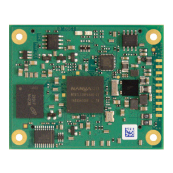
Part I: PCM-049/phyCORE-OMAP44xx System on Module phyCORE-OMAP44xx 1.1.2 View of the phyCORE-OMAP44xx Figure 2: Top view of the phyCORE-OMAP44xx (controller side) © PHYTEC Messtechnik GmbH 2012 L-760e_1... -
Page 27: Figure 3: Bottom View Of The Phycore-Omap44Xx (Connector Side)
Part I: PCM-049/phyCORE-OMAP44xx System on Module Figure 3: Bottom view of the phyCORE-OMAP44xx (connector side) L-760e_1 © PHYTEC Messtechnik GmbH 2012... -
Page 28: 3Minimum Requirements To Operate The Phycore-Omap44Xx
In addition, proper implementation of the phyCORE-OMAP44xx module into a target application also requires connecting all GND pins neighboring signals that are being used in the application circuitry. Please refer to Section 1.4 for more information. © PHYTEC Messtechnik GmbH 2012 L-760e_1... -
Page 29: Pin Description
BSP. To support all features of the phyCORE-OMAP44xx Carrier Board a few changes have been made in the BSP delivered with the module. Table 42 lists all pins with functions different to what is described in Table L-760e_1 © PHYTEC Messtechnik GmbH 2012... -
Page 30: Figure 4: Pin-Out Of The Phycore-Connector (Top View, With Cross Section Insert)
Note: SL is short for Signal Level (V) and is the applicable logic level to interface a given pin. Those pins marked as “N/A” have a range of applicable values that constitute proper operation. © PHYTEC Messtechnik GmbH 2012 L-760e_1... -
Page 31: Table 2: Pin-Out Of The Phycore-Connector X1, Row A
VCC_MMC1 SDMMC1 data bit 1 X_SDMMC1_DAT2 VCC_MMC1 SDMMC1 data bit 2 X_SDMMC1_DAT3 VCC_MMC1 SDMMC1 data bit 3 X_SDMMC1_DAT4 VCC_MMC1 SDMMC1 data bit 4 Ground 0V Table 2: Pin-out of the phyCORE-Connector X1, Row A L-760e_1 © PHYTEC Messtechnik GmbH 2012... - Page 32 VCC_1V8_IO DISPC data bit 12 X_DISPC_DATA10 VCC_1V8_IO DISPC data bit 10 Ground 0V X_DISPC_DATA8 VCC_1V8_IO DISPC data bit 8 X_DISPC_DATA6 VCC_1V8_IO DISPC data bit 6 Table 2: Pin-out of the phyCORE-Connector X1, Row A © PHYTEC Messtechnik GmbH 2012 L-760e_1...
-
Page 33: Table 3: Pin-Out Of The Phycore-Connector X1, Row B
1.8 V / VCC_1V8_IO Camera sensor reset X_CAM_STROBE VCC_1V8_IO Camera flash activation trigger X_FREF_CLK1_OUT VCC_1V8_IO FREF clock 1 output Ground 0V X_CSI21_DX2 CSI2-A (CSI21) differential data lane positive input 2 Table 3: Pin-out of the phyCORE-Connector X1, Row B L-760e_1 © PHYTEC Messtechnik GmbH 2012... - Page 34 Ground 0V X_McBSP3_FSX 1.8 V / VCC_1V8_IO ABE McBSP3 combined frame synchronization X_McBSP3_DR 1.8 V ABE McBSP3 received serial data X_DISPC_DATA23 VCC_1V8_IO DISPC data bit 23 Table 3: Pin-out of the phyCORE-Connector X1, Row B © PHYTEC Messtechnik GmbH 2012 L-760e_1...
-
Page 35: Table 4: Pin-Out Of The Phycore-Connector X1, Row C
Backup battery input X_nRESET_WARM 1.8 V Warm Reset Input X_PMIC_PWRON 3.3 V PMIC power on input X_UART1_TX VCC_1V8_IO Serial transmit signal UART 1 Ground 0V Table 4: Pin-out of the phyCORE-Connector X1, Row C L-760e_1 © PHYTEC Messtechnik GmbH 2012... - Page 36 HDMI display data 0 differential positive or negative X_HDMI_DATA0Y HDMI HDMI display data 0 differential positive or negative X_HDMI_CLOCKX HDMI HDMI display clock differential positive or negative Table 4: Pin-out of the phyCORE-Connector X1, Row C © PHYTEC Messtechnik GmbH 2012 L-760e_1...
- Page 37 System boot configuration pin 4 Ground 0V Table 4: Pin-out of the phyCORE-Connector X1, Row C Can be configured by setting the appropriate control register. Please refer to the OMAP44xx Reference manual for more information. L-760e_1 © PHYTEC Messtechnik GmbH 2012...
-
Page 38: Table 5: Pin-Out Of The Phycore-Connector X1, Row D
VCC_3V3_S Ethernet receive positive input X_ETH_RX- VCC_3V3_S Ethernet receive negative input X_ETH_LINK VCC_3V3_S Ethernet link indicator (open drain) X_GPIO_WK30 1.8 V / VCC_1V8_IO GPIO WK30 Table 5: Pin-out of the phyCORE-Connector X1, Row D © PHYTEC Messtechnik GmbH 2012 L-760e_1... - Page 39 C3 clock (open drain) X_I2C3_SDA 1.8 V / VCC_1V8_IO I C3 data (open drain) X_PMIC_EXTCHRG_ENZ 1.8 V Output control signal to an external VAC charger Table 5: Pin-out of the phyCORE-Connector X1, Row D L-760e_1 © PHYTEC Messtechnik GmbH 2012...
- Page 40 1.8 V System boot configuration pin 5 Table 5: Pin-out of the phyCORE-Connector X1, Row D Can be configured by setting the appropriate control register. Please refer to the OMAP44xx Reference manual for more information. © PHYTEC Messtechnik GmbH 2012 L-760e_1...
-
Page 41: Jumpers
Please pay special attention to the "TYPE" column to ensure you are using the correct type of jumper (0 Ohms, 10 k Ohms, etc…). The jumpers are 0402 package with a 1/8 W or better power rating, while JN1 is a resistor array (1206). L-760e_1 © PHYTEC Messtechnik GmbH 2012... -
Page 42: Figure 6: Jumper Locations (Top View)
Part I: PCM-049/phyCORE-OMAP44xx System on Module phyCORE-OMAP44xx Figure 6: Jumper Locations (top view) © PHYTEC Messtechnik GmbH 2012 L-760e_1... -
Page 43: Figure 7: Jumper Locations (Bottom View)
Part I: PCM-049/phyCORE-OMAP44xx System on Module Figure 7: Jumper Locations (bottom view) L-760e_1 © PHYTEC Messtechnik GmbH 2012... -
Page 44: Table 6: Phycore-Omap44Xx Jumper Settings
1+2 Pin AH24 (DMTIMER9) of controller U1 is connected to phyCORE-Connector X1, which means that pin X1A43 can be used as PWM output for brightness control 2+3 Pin AG12 (USBB2_ULPITTL_CLK) of controller U2 is connected to phyCORE-Connector X1 Table 6: phyCORE-OMAP44xx Jumper Settings © PHYTEC Messtechnik GmbH 2012 L-760e_1... - Page 45 X1B8 11 + 12 connect pairwise) Table 6: phyCORE-OMAP44xx Jumper Settings This option is intend for applications without display, but the need for the complete set of signals of the second ULPI interface. L-760e_1 © PHYTEC Messtechnik GmbH 2012...
- Page 46 Part I: PCM-049/phyCORE-OMAP44xx System on Module phyCORE-OMAP44xx © PHYTEC Messtechnik GmbH 2012 L-760e_1...
-
Page 47: Power
PMIC which again supplies the RTC and some critical registers if the primary system power (VCC_3V3_IN) is removed. Applications not requiring a backup mode can connect the VBAT pin to the primary system power supply (VCC = 3.3 V), or can leave it open. L-760e_1 © PHYTEC Messtechnik GmbH 2012... -
Page 48: 3Power Management Ic (U5)
X1B18 (switchable between 3 V and 1.8 V via PMIC register, default 3 V) • VCC_3V3_S (3.3 V) RS-232 Transceiver, USB PHY, Ethernet controller, User LEDs, 3V3_S reference voltage at phyCORE-Connector X1D23 (connected to main supply VCC_3V3 through FET Q3, switchable via PMIC REGEN1 output) © PHYTEC Messtechnik GmbH 2012 L-760e_1... -
Page 49: Figure 8: Power Supply Diagram
Part I: PCM-049/phyCORE-OMAP44xx System on Module Figure 8: Power Supply Diagram L-760e_1 © PHYTEC Messtechnik GmbH 2012... -
Page 50: Real Time Clock (Rtc)
C inter- face. At the time of delivery only the generation of the required voltages is implemented . Please refer to the TWL6030 Technical Ref. Man. for more information on how to program the PMIC. © PHYTEC Messtechnik GmbH 2012 L-760e_1... -
Page 51: External Battery Charging
GPADC4. Please consider, because of system measuring errors the determined value doesn't equate exactly to the phyCORE's current consumption (measuring error ± 5%). The GPADCs and the measured values can be read out via the I2C1 bus. L-760e_1 © PHYTEC Messtechnik GmbH 2012... -
Page 52: 4Reference Voltages
Please take care not to load the reference voltage too heavily to avoid any disfunction or damage of the module. The following maximum loads are allowed: • VCC_1V8_IO (1.8 V): 400 mA • VCC_MMC1 (3 V/1.8 V): 150 mA • VCC_3V3_S (3.3 V): 500 mA © PHYTEC Messtechnik GmbH 2012 L-760e_1... -
Page 53: System Configuration And Booting
This mode is selected when sys_boot[5] is tied low. Note: Only permanent booting devices (marked in bold) are put on the booting list in case of a warm reset, as peripheral booting is normally not applicable after a warm reset. L-760e_1 © PHYTEC Messtechnik GmbH 2012... -
Page 54: Table 9: Boot Modes Of The Phycore-Omap44Xx (Memory Type Devices Preferred)
UART MMC1 NAND 011010 UART MMC2 (multi- plexed with MMC5, only dat0-3) 011011 UART MMC1 011100 MMC2 (multi- plexed with MMC5, only dat0-3) Table 10: Boot Modes of the phyCORE-OMAP44xx (peripheral type devices preferred) © PHYTEC Messtechnik GmbH 2012 L-760e_1... -
Page 55: System Memory
SDRAM must be initialized by accessing the appropriate SDRAM configuration registers on the OMAP44xx controller. Refer to the OMAP44xx Reference Manual for accessing and configuring these registers. L-760e_1 © PHYTEC Messtechnik GmbH 2012... -
Page 56: 2Nand Flash Memory (U4)
NAND Flash lock state Block lock commands disabled 1 + 2 or not mounted Block lock commands enabled 2 + 3 Table 12: NAND Flash Lock Control via J4 Defaults are in text bold blue © PHYTEC Messtechnik GmbH 2012 L-760e_1... -
Page 57: 3I2C Eeprom (U2)
EEPROM Write Protection State Write access allowed closed Write protected open Table 14: EEPROM Write Protection States via J5 Defaults are in bold blue text See the manufacturer’s data sheet for interfacing and operation L-760e_1 © PHYTEC Messtechnik GmbH 2012... -
Page 58: 4Memory Model
There is no special address decoding device on the phyCORE-OMAP44xx, which means that the memory model is given according to the memory mapping of the OMAP44xx. Please refer to the OMAP44xx Reference Manual for more information on the memory mapping. © PHYTEC Messtechnik GmbH 2012 L-760e_1... -
Page 59: Sd / Mmc Card Interfaces
SDMMC1 data bit 6 X1A30 X_SDMMC1_DAT7 VCC_MMC1 SDMMC1 data bit 7 X1B27 X_PMIC_MMC1_CD I 1.8 V SDMMC1 card insertion and extraction detection X1B18 VCC_MMC1 SDMMC1 reference voltage Table 15: Location of SD/ MMC Card Interface Signals (SDMMC1) L-760e_1 © PHYTEC Messtechnik GmbH 2012... -
Page 60: Table 16: Location Of Sd/ Mmc Card Interface Signals (Sdmmc5)
VCC_1V8_IO (X1B30) at one of the supply rails. Please take care to not load the reference voltage VCC_1V8_IO too heavily to avoid any disfunction or damage of the module. The maximum load is 400 mA. © PHYTEC Messtechnik GmbH 2012 L-760e_1... -
Page 61: Serial Interfaces
VCC_1V8_IO (X1B30) at one of the supply rails should be used. Please take care to not load the reference voltage VCC_1V8_IO too heavily to avoid any disfunction or damage of the module. The maximum load is 400 mA. L-760e_1 © PHYTEC Messtechnik GmbH 2012... -
Page 62: 1Universal Asynchronous Interface
X1C15 X_UART2_RTS VCC_1V8_IO Serial request to send UART 2 X1D16 X_UART4_TX VCC_1V8_IO Serial transmit signal UART 4 X1D17 X_UART4_RX 1.8 V Serial data receive signal UART 4 Table 17: Location of the UART Signals © PHYTEC Messtechnik GmbH 2012 L-760e_1... -
Page 63: 2Usb Otg Interface
(refer to the USB3320 datasheet for more information). Removing R34 and mounting Q5 and R21 allows to also generate this signal by GPIO 119 of the OMAP44xx if needed. Please contact our sales team for more details. L-760e_1 © PHYTEC Messtechnik GmbH 2012... -
Page 64: 4Full-Speed Ic Usb Host Interface
The Ethernet controller's integrated PHY supports HP Auto-MDIX technology, eliminating the need for the consideration of a direct connect LAN cable, or a cross-over patch cable. It detects the TX and RX pins of the © PHYTEC Messtechnik GmbH 2012 L-760e_1... -
Page 65: Mac Address Eeprom (U13)
The Ethernet controller is connected to chip select CS5 of the General-Purpose Memory Controller (GPMC). The start address for CS5 is configurable (e.g. for the Phytec Linux BSP the start address is set to 0x2C00 0000). Please refer to the OMAP44xx Reference Manual for more information on how to configure the address space for CS5 etc. -
Page 66: 6I2C Interface
Section 1.6.3.1 for alternative address settings. C Interface Connected Devices C Address Maximum Speed (standard)(7 MSB) I2C1 EEPROM 0x50 400 kHz I2C1 PMIC 0x48, 0x49, 0x4A 400 kHz Table 23: I C Addresses in Use © PHYTEC Messtechnik GmbH 2012 L-760e_1... -
Page 67: 7Spi Interface
1.8 V / VCC_1V8_IO ABE McBSP3 transmitted serial data X1B41 X_McBSP3_FSX 1.8 V / VCC_1V8_IO ABE McBSP3 combined frame synchronization X1B42 X_McBSP3_DR 1.8 V ABE McBSP3 received serial data Table 25: McBSP Signal Location L-760e_1 © PHYTEC Messtechnik GmbH 2012... -
Page 68: 9Multichannel Audio Serial Port (Mcasp)
X1B38 X_McASP_AMUTE VCC_1V8_IO ABE McASP auto mute output X1A39 X_McASP_AMUTEIN 1.8 V ABE McASP auto mute input X1A41 X_McASP_ACLKX VCC_1V8_IO ABE McASP clock transmit Table 26: Multichannel Audio Serial Port (McASP) Signal Location © PHYTEC Messtechnik GmbH 2012 L-760e_1... -
Page 69: General Purpose I/Os
To support all features of the phyCORE-OMAP44xx Carrier Board special functions have been assigned to the GPIOs in the BSP delivered with the module. In order to otherwise utilize the GPIOs the software must be changed. Table 42 lists the functions assigned to the GPIO pins. L-760e_1 © PHYTEC Messtechnik GmbH 2012... - Page 70 Part I: PCM-049/phyCORE-OMAP44xx System on Module phyCORE-OMAP44xx © PHYTEC Messtechnik GmbH 2012 L-760e_1...
-
Page 71: Debug Interface (X7)
X1 is shown in Table PHYTEC offers a JTAG-Emulator adapter (order code JA-002) for connecting the phyCORE-OMAP44xx to a standard emulator. The JTAG-Emulator adapter extends the signals of the module's JTAG connector to a standard ARM connector with 2 mm pin pitch. The JA-002 therefore functions as an adapter for connecting the module's non-ARM-compatible JTAG connector X7 to standard Emulator connectors. -
Page 72: Table 29: Location Of The Jtag Signals On The Phycore-Connector X1
JTAG ARM clock emulation X1C33 X_DPM_EMU1 1.8 V / VCC_1V8_IO Debug pin manager pin 1 X1D33 X_DPM_EMU0 1.8 V / VCC_1V8_IO Debug pin manager pin 0 Table 29: Location of the JTAG Signals on the phyCORE-Connector X1 © PHYTEC Messtechnik GmbH 2012 L-760e_1... -
Page 73: Figure 9: Jtag Interface At X7 (Top View)
Part I: PCM-049/phyCORE-OMAP44xx System on Module Figure 9: JTAG Interface at X7 (top view) L-760e_1 © PHYTEC Messtechnik GmbH 2012... -
Page 74: Figure 10: Jtag Interface At X7 (Bottom View)
Part I: PCM-049/phyCORE-OMAP44xx System on Module phyCORE-OMAP44xx Figure 10: JTAG Interface at X7 (bottom view) © PHYTEC Messtechnik GmbH 2012 L-760e_1... -
Page 75: Display Interfaces
Part I: PCM-049/phyCORE-OMAP44xx System on Module 1.11 Display Interfaces The phyCORE-OMAP44xx provides three different display interfaces: 1. Parallel Display Interface 2. MIPI® Display Serial Interface (DSI) 3. High-Definition Multimedia Interface (HDMI) L-760e_1 © PHYTEC Messtechnik GmbH 2012... -
Page 76: 1Parallel Display Interface
DISPC data bit 0 X1B58 X_DISPC_HSYNC VCC_1V8_IO DISPC horizontal synchronization X1A59 X_DISPC_PCLK VCC_1V8_IO DISPC LCD pixel clock X1B59 X_DISPC_VSYNC VCC_1V8_IO DISPC vertical synchronization X1A60 X_DISPC_DE VCC_1V8_IO DISPC data enable Table 30: Parallel Display Interface Signal Location © PHYTEC Messtechnik GmbH 2012 L-760e_1... -
Page 77: 2Mipi Display Serial Interface (Dsi)
X1C52 X_DSI1_DY4 DSI1 display lane 4 differential positive or negative Table 31: DSI Signal Location Can be configured by setting the appropriate control register. Please refer to the OMAP44xx Reference manual for more information. L-760e_1 © PHYTEC Messtechnik GmbH 2012... -
Page 78: 3High-Definition Multimedia Interface (Hdmi)
X1C40 X_HDMI_CLOCKY HDMI HDMI display clock differential positive or negative Table 32: HDMI Signal Location Can be configured by setting the appropriate control register. Please refer to the OMAP44xx Reference manual for more information. © PHYTEC Messtechnik GmbH 2012 L-760e_1... -
Page 79: Camera Interfaces
Pin # Signal Description X1B10 X_CAM_SHUTTER VCC_1V8_IO Mechanical shutter control signal X1B11 X_CAM_GLOBAL_RESET 1.8 V / VCC_1V8_IO Camera sensor reset X1B12 X_CAM_STROBE VCC_1V8_IO Camera flash activation trigger Table 33: Camera Interface Control Signal Location L-760e_1 © PHYTEC Messtechnik GmbH 2012... -
Page 80: 1Primary Camera Interface (Csi2-A/Csi21)
In order to use lanes 3 and 4 of the primary camera interface JN1 must be set to position 2. Please refer to Figure 6 to see where JN1 is located. © PHYTEC Messtechnik GmbH 2012 L-760e_1... -
Page 81: 2Secondary Camera Interface (Csi2-B/Csi22)
X_CSI22_DY0 CSI2-B (CSI22) differential clock lane negative input X1A10 X_CSI22_DX1 CSI2-B (CSI22) differential data lane positive input X1A11 X_CSI22_DY1 CSI2-B (CSI22) differential data lane negative input Table 35: Secondary Camera Interface (CSI2-B/CSI22) Signal Location L-760e_1 © PHYTEC Messtechnik GmbH 2012... -
Page 82: Keyboard Interface
3 and 4 of the primary camera interface. The resistor array JN1 allows to choose which signals are brought out at these pins. The default setting of JN1 at position 1 allows to use the keyboard interface without changes. Please refer to Table 6 for more information on JN1. © PHYTEC Messtechnik GmbH 2012 L-760e_1... -
Page 83: User Leds
The phyCORE-OMAP44xx provides two user LEDs on board, a red (D2) and a green (D3). The LEDs can be controlled by setting GPIO 152 (D2) and GPIO 153 (D3) to the desired output level. A high-level turns the LED on, a low-level turns it off. L-760e_1 © PHYTEC Messtechnik GmbH 2012... - Page 84 Part I: PCM-049/phyCORE-OMAP44xx System on Module phyCORE-OMAP44xx © PHYTEC Messtechnik GmbH 2012 L-760e_1...
-
Page 85: Technical Specifications
2.0 mm on the top (microcontroller) side. The board itself is approximately 1.5 mm thick. Figure 11: Physical Dimensions Note: To facilitate the integration of the phyCORE-OMAP44xx into your design, the footprint of the phyCORE- OMAP44xx is available (see also Section 1.16.1). L-760e_1 © PHYTEC Messtechnik GmbH 2012... - Page 86 120 (2 Rows of 60 pins each) Samtec part number (lead free) BTH-060-01-L-D-A (header) PHYTEC part number (lead free) VM240 Different heights are offered for the receptacle sockets that correspond to the connectors populating the underside of the phyCORE-OMAP44xx. The connector height given above indicates the distance between the two connected PCBs when the module is mounted on the corresponding carrier board.
-
Page 87: Hints For Integrating And Handling The Phycore-Omap44Xx
• the design of the standard phyCORE Carrier Board can be used as a reference for any customer application. • many answers to common questions can be found at http://www.phytec.de/de/support/faq/faq-phyCORE- OMAP44xx.html, or http://www.phytec.eu/europe/support/faq/faq-phyCORE-OMAP44xx.html. • the link "Carrier Board" within the category Dimensional Drawing leads to the layout data as shown in Figure 12 . -
Page 88: Figure 12: Footprint Of The Phycore-Omap44X
Part I: PCM-049/phyCORE-OMAP44xx System on Module phyCORE-OMAP44xx Figure 12: Footprint of the phyCORE-OMAP44x © PHYTEC Messtechnik GmbH 2012 L-760e_1... -
Page 89: Component Placement Diagram
Part I: PCM-049/phyCORE-OMAP44xx System on Module 1.17 Component Placement Diagram Figure 13: phyCORE-OMAP44xx Component Placement (top view) L-760e_1 © PHYTEC Messtechnik GmbH 2012... -
Page 90: Figure 14: Phycore-Omap44Xx Component Placement (Bottom View)
Part I: PCM-049/phyCORE-OMAP44xx System on Module phyCORE-OMAP44xx Figure 14: phyCORE-OMAP44xx Component Placement (bottom view) © PHYTEC Messtechnik GmbH 2012 L-760e_1... -
Page 91: Part Ii: Pcm-959/Phycore-Omap44Xx Carrier Board
SOM is deployed. Carrier Board schematics with BoM are available under a Non Disclosure Agreement (NDA). Re-use of carrier board circuitry likewise enables users of PHYTEC SOMs to shorten time-to-market, reduce development costs, and avoid substantial design issues and risks. - Page 92 Part II: PCM-959/phyCORE-OMAP44xx Carrier Board phyCORE-OMAP44xx © PHYTEC Messtechnik GmbH 2012 L-760e_1...
-
Page 93: Introduction
PHYTEC System on Module (SOM) modules. phyCORE-OMAP44xx Carrier Boards are designed for evaluation, testing and prototyping of PHYTEC System on Modules in laboratory environments prior to their use in customer designed applications. -
Page 94: 1Concept Of The Phycore-Omap44Xx Carrier Board
DB-9, USB and Ethernet allowing for use of the SOM's interfaces with standard cable. The following sections contain specific information relevant to the operation of the phyCORE-OMAP44xx mounted on the phyCORE-OMAP44xx Carrier Board. © PHYTEC Messtechnik GmbH 2012 L-760e_1... -
Page 95: 2Overview Of The Phycore-Omap44Xx Carrier Board Peripherals
Figure 15 Figure 16 highlight the location of each peripheral for easy identification. Figure 15: phyCORE-OMAP44xx Carrier Board Overview of Connectors, LEDs and Buttons (top view) L-760e_1 © PHYTEC Messtechnik GmbH 2012... -
Page 96: Figure 16: Phycore-Omap44Xx Carrier Board Overview Of Connectors, Leds And Buttons (Bottom View)
Part II: PCM-959/phyCORE-OMAP44xx Carrier Board phyCORE-OMAP44xx Figure 16: phyCORE-OMAP44xx Carrier Board Overview of Connectors, LEDs and Buttons (bottom view) © PHYTEC Messtechnik GmbH 2012 L-760e_1... -
Page 97: Connectors And Pin Header
HDMI-DVI connector Section 2.1.3.8 Serial Interfaces, 2 x DB-9 female Section 2.1.3.3 BAT1 Battery holder for standard CR 2032 lithium coin cell Section 2.1.3.18 Table 37: phyCORE-OMAP44xx Carrier Board Connectors and Pin Headers L-760e_1 © PHYTEC Messtechnik GmbH 2012... -
Page 98: Switches
1st: NAND, 2nd: USB, 3rd: UART, 4th: MMC1 (please refer to Section 2.1.3.17 for more information). Button Description See Chapter Configuration of pins X_BOOT[0] and X_BOOT[1] Section 2.1.3.17 Configuration of pins X_BOOT[2:5] Table 39: phyCORE-OMAP44xx Carrier Board DIP-Switch Descriptions © PHYTEC Messtechnik GmbH 2012 L-760e_1... -
Page 99: Leds
User LED 2 yellow User LED 3 User LED 4 Table 40: phyCORE-OMAP44xx Carrier Board LEDs Descriptions Note: Detailed descriptions of the assembled connectors, jumpers and switches can be found in the following chapters. L-760e_1 © PHYTEC Messtechnik GmbH 2012... -
Page 100: Jumpers
Carefully heat neighboring connections in pairs. After a few alternations, components can be removed with the solder-iron tip. Alternatively, a hot air gun can be used to heat and loosen the bonds. © PHYTEC Messtechnik GmbH 2012 L-760e_1... -
Page 101: Figure 18: Phycore-Omap44Xx Carrier Board Jumper Locations (Top View)
Part II: PCM-959/phyCORE-OMAP44xx Carrier Board Figure 18: phyCORE-OMAP44xx Carrier Board Jumper Locations (top view) L-760e_1 © PHYTEC Messtechnik GmbH 2012... -
Page 102: Figure 19: Phycore-Omap44Xx Carrier Board Jumper Locations (Bottom View)
Part II: PCM-959/phyCORE-OMAP44xx Carrier Board phyCORE-OMAP44xx Figure 19: phyCORE-OMAP44xx Carrier Board Jumper Locations (bottom view) © PHYTEC Messtechnik GmbH 2012 L-760e_1... - Page 103 X20. the phyCORE- OMAP44xx ! open VCC_CAM-1 not connected; first phyCAM-P interface Camera_1 not available closed Supply voltage VCC_CAM-1 connected; first phyCAM-P interface Camera_1 can be used Table 41: phyCORE-OMAP44xx Carrier Board Jumper Settings L-760e_1 © PHYTEC Messtechnik GmbH 2012...
- Page 104 Jumper JP13 selects either the parallel, or the DSI display Section 2.1.3.7.1 interface of the phyCORE-OMAP44xx as source for the PHYTEC Display -Interface (PDI) at connector X12 open Data of the parallel display interface of the phyCORE- OMAP44xx brought out at PDI-Connector X12...
- Page 105 USB_OTG_OC to pin X1D42 (X_SYS_NIRQ2) of the phyCORE- OMAP44xx which connects to GPIO 183 of the OMAP44xx open disconnected closed USB_OTG_OC can be evaluated at GPIO 183 of the OMAP44xx Table 41: phyCORE-OMAP44xx Carrier Board Jumper Settings L-760e_1 © PHYTEC Messtechnik GmbH 2012...
- Page 106 OMAP44xx's camera sensor reset signal X_CAM_GLOBAL_RESET Camera reset is triggered by the PMIC's system reset signal X_nRESET_PWRON The camera sensor reset signal X_CAM_GLOBAL_RESET resets a camera connected to X4 Table 41: phyCORE-OMAP44xx Carrier Board Jumper Settings © PHYTEC Messtechnik GmbH 2012 L-760e_1...
-
Page 107: Table 41: Phycore-Omap44Xx Carrier Board Jumper Settings
1+2 (10 k Rising edge strobe used for the LVDS display signals resistor) Falling edge strobe used for the LVDS display signals Table 41: phyCORE-OMAP44xx Carrier Board Jumper Settings Default settings are in bold blue text L-760e_1 © PHYTEC Messtechnik GmbH 2012... -
Page 108: 3Functional Components On The Phycore-Omap44Xx Carrier Board
Samtec connectors guarantee optimal connection and proper insertion of the phyCORE-OMAP44xx. Please make sure that the phyCORE-OMAP44xx is fully plugged into the matting connectors of the carrier board. Otherwise individual signals may have a bad, or no contact. © PHYTEC Messtechnik GmbH 2012 L-760e_1... -
Page 109: Table 42: Specifically Used Pins On The Phycore-Connector
BSP utilizing GPIO 183 of the OMAP44xx. Table 42: Specifically used Pins on the phyCORE-Connector Can be disconnected by changing jumper J13 Opening jumper J5 disconnects USB_OTG_OC from the phyCORE-Connector L-760e_1 © PHYTEC Messtechnik GmbH 2012... -
Page 110: Power
5 V voltage domain to supply the 1.8 V and 1.2 V regulators VCC_1V8 1.8 V voltage domain supplying some peripherals (e.g. audio codec, etc.) VCC_1V2 1.2 V voltage domain to supply DSI2LVDS Bridge Chip only Table 43: Voltage Domains on the Carrier Board © PHYTEC Messtechnik GmbH 2012 L-760e_1... -
Page 111: Wall Adapter Input (X6)
An adapter with a minimum supply of 2.0 A is recommended. Figure 22: Power Connector Corresponding to Wall Adapter Input X6 It is necessary to ensure that jumper JP5 is open in order to supply power to the phyCORE module! L-760e_1 © PHYTEC Messtechnik GmbH 2012... -
Page 112: Power Over Ethernet (Poe)
3. To restart the system press button S3 for a maximum time of 1000 ms. » All power LEDs should light up again and the phyCORE sends serial data from UART3 to the top DB-9 sub-connector of connector P1. © PHYTEC Messtechnik GmbH 2012 L-760e_1... -
Page 113: Power Management
C interface. At the time of delivery only the generation of the required voltages is implemented . Please refer to the TWL6030 Technical Ref. Man. for more information on how to program the PMIC. L-760e_1 © PHYTEC Messtechnik GmbH 2012... -
Page 114: Connectivity To Universal Asynchronous Interfaces (P1 + X5)
P1 at RS-232 level, whereas the signals of UART1 are brought out on the expansion connector X5 at TTL level. Figure 24 shows the signal mapping of the two female DB-9 connectors at connector P1. Figure 24: RS-232 connector P1 Signal Mapping © PHYTEC Messtechnik GmbH 2012 L-760e_1... -
Page 115: Connectivity To Uart 1 (Ttl)
The RS-232 transceiver on the phyCORE-OMAP44xx is configured to operate in AutoShutdown mode, which means that it shuts down if invalid signals are detected (Please refer to Section 1.8.1 and the datasheet of the MAX3380E/MAX3381E for more information). L-760e_1 © PHYTEC Messtechnik GmbH 2012... -
Page 116: Table 48: Operation States Of The Rs-232 Transceiver Max3380
(shutdown after 30 s without receive, or transmit signal, or if signal is invalid) Normal Operation not mounted not mounted mounted mounted (AutoShutdown, shutdown if signal is invalid) Table 49: Possible Configurations of the MAX3380 RS-232 Transceiver © PHYTEC Messtechnik GmbH 2012 L-760e_1... -
Page 117: Ethernet Connectivity (X9)
Ethernet controller's supply voltage VCC_3V3_S is turned off by the power management on the phyCORE- OMAP44xx. Please refer to Section 1.8.5.1 for more information. The Ethernet interface also supports Power over Ethernet (PoE). Please refer to Section 2.1.3.2.2 for more information. L-760e_1 © PHYTEC Messtechnik GmbH 2012... -
Page 118: Usb Host Connectivity (X8, X12,X18,X19)
Table 50 shows the distribution of the seven downstream facing ports to the different connectors. please refer to Table 51 to locate the signals on the display data connectors X12 please see Section 2.1.3.15 © PHYTEC Messtechnik GmbH 2012 L-760e_1... -
Page 119: Table 50: Distribution Of The Usb Hub's (U7) Ports
USB3 20 pin header Row (pins 19 (D-) and 20 (D+)) USB2 20 pin header Row (pins 19 (D-) and 20 (D+)) USB1 USB A Table 50: Distribution of the USB Hub's (U7) Ports L-760e_1 © PHYTEC Messtechnik GmbH 2012... -
Page 120: Usb Otg Connectivity (X7)
USB OTG cable. However, given the limited number of OTG enabled devices in the embedded market this jumper is provided to either simulate an OTG cable, or force the OTG interface into Host mode when OTG operation is not required. LED D27 signals VBUS power output. © PHYTEC Messtechnik GmbH 2012 L-760e_1... -
Page 121: Display / Touch Connectivity (X12, X13)
Part II: PCM-959/phyCORE-OMAP44xx Carrier Board 2.1.3.7 Display / Touch Connectivity (X12, X13) Figure 28: Display / Touch Connectivity (X12, X13)(top view) Figure 29: Display / Touch Connectivity (X12, X13)(bottom view) L-760e_1 © PHYTEC Messtechnik GmbH 2012... -
Page 122: Pdi Data Connector (X12)
The parallel display interface and the DSI interface signals are converted into LVDS and are available at the PHYTEC Display -Interface (PDI) which is described in the following paragraph. In addition, the parallel display interface is available at expansion connector X5. -
Page 123: Table 51: Pdi Display Data Connector X12 Signal Description
USB hub at U7) USB1DN_DM4 3.3 V USB data - (port 4 of the USB hub at U7)2 Ground DISP_LVDS_0- 3.3 V LVDS data channel 0 negative output Table 51: PDI Display Data Connector X12 Signal Description L-760e_1 © PHYTEC Messtechnik GmbH 2012... - Page 124 Light sensor analog input Table 51: PDI Display Data Connector X12 Signal Description Provided to supply any logic on the display adapter. Max. draw 100 mA LED D22 signals use of this USB interface © PHYTEC Messtechnik GmbH 2012 L-760e_1...
-
Page 125: Table 52: Auxiliary Interfaces At Pdi Data Connector X12
0 V to V (VCC_3V3AD). Table 52: Auxiliary Interfaces at PDI Data Connector X12 Jumper J6 on the phyCORE-OMAP44xx must be configured at 1+2 to have this signal available (see Table L-760e_1 © PHYTEC Messtechnik GmbH 2012... -
Page 126: Pdi Power Connector (X13)
C bus I2C4 at address 0x41. By changing jumper J9 the address can be set to 0x44 if needed (refer to Table 41). An additional interrupt output is connected to GPIO 117 (X1A39 on the phyCORE-Connector) of the OMAP44xx. © PHYTEC Messtechnik GmbH 2012 L-760e_1... -
Page 127: Hdmi - Dvi Connectivity (X23)
(HPD) signal. Level shifters shift the I C interface signals and the hot plug detect signal from the IO voltage (VCC_1V8IO) to 5 V, while the data and clock signals extend directly from the phyCORE-Connector to the DVI receptacle. L-760e_1 © PHYTEC Messtechnik GmbH 2012... -
Page 128: Table 54: Dvi Connector X23
Ground not connected not connected Ground X_HDMI_CLOCKY HDMI HDMI clock positive output X_HDMI_CLOCKX HDMI HDMI clock negative output not connected not connected not connected not connected not connected Table 54: DVI Connector X23 © PHYTEC Messtechnik GmbH 2012 L-760e_1... - Page 129 Part II: PCM-959/phyCORE-OMAP44xx Carrier Board Pin # Signal Description Earth Earth Earth Earth Earth Earth Table 54: DVI Connector X23 L-760e_1 © PHYTEC Messtechnik GmbH 2012...
-
Page 130: Camera Interfaces (X4, X5)
Part II: PCM-959/phyCORE-OMAP44xx Carrier Board phyCORE-OMAP44xx 2.1.3.9 Camera Interfaces (X4, X5) Figure 31: Camera Interfaces (top view) Figure 32: Camera Interfaces (bottom view) © PHYTEC Messtechnik GmbH 2012 L-760e_1... -
Page 131: Primary Camera Interface Csi2-A/Csi21 (X5)
4 (see note below) X5C27 X_KPD_ROW5_CSI21_DY4 1.8 V / CSI Keyboard row 5 / CSI2-A (CSI21) differential data lane negative input 4 (see note below) Table 55: Primary Camera Interface CSI2-A/CSI21 at Expansion Connector X5 L-760e_1 © PHYTEC Messtechnik GmbH 2012... -
Page 132: Secondary Camera Interface Csi2-B/Csi22 (X4)
The secondary camera interface (CSI2-B/CSI22 ) of the phyCORE-OMAP44xx is available at FFC connector X4 (Camera_2 interface of the phyCORE-OMAP44xx carrier board), which is compatible to PHYTEC's phyCAM-P camera interface standard. It provides connectivity to an 8-bit parallel camera interface. The camera serializer at U1 (SN65LVDS315RGER) converts the 8-bit parallel camera data to MIPI-CSI1 compliant serial data. -
Page 133: Table 57: Secondary Camera Interface Csi-B/Csi22 At Camera Connector X4
C data line Ground CAM-2_RST VCC_CAM-2 Camera_2 reset VCC_CAM-2 1.8 V - 3.3 V Camera_2 supply voltage VCC_CAM-2 1.8 V - 3.3 V Camera_2 supply voltage Table 57: Secondary Camera Interface CSI-B/CSI22 at Camera Connector X4 L-760e_1 © PHYTEC Messtechnik GmbH 2012... -
Page 134: Camera Auxiliary Connector (X2)
Reserved for future use CAM-1_VS VCC_CAM-1 Reserved for future use CAM-1_HS VCC_CAM-1 Reserved for future use Ground Table 58: Camera Auxiliary Connector X2 JP6 must be closed to have VCC_CAM_1 available at the camera auxiliary connector X2 © PHYTEC Messtechnik GmbH 2012 L-760e_1... - Page 135 Reserved for future use CAM-1_DD0 VCC_CAM-1 Reserved for future use Ground CAM-1_PCLK VCC_CAM-1 Reserved for future use Ground CAM-1_MCLK VCC_CAM-1 Reserved for future use Ground CAM-1_VSET Camera supply voltage configuration Table 58: Camera Auxiliary Connector X2 L-760e_1 © PHYTEC Messtechnik GmbH 2012...
-
Page 136: 10Audio Connectivity (X5, X14, X15, X17)
2.1.3.10 Audio Connectivity (X5, X14, X15, X17) Figure 33: Components supporting the Audio Interface at connectors X5, X14, X15 and X17 (top view) Figure 34: Components supporting the Audio Interface at connectors X5, X14, X15 and X17 (bottom view) © PHYTEC Messtechnik GmbH 2012 L-760e_1... - Page 137 GND. In this configuration jack detection is disabled. Connecting the shield contact to the HPCOM output driver of the stereo audio codec at U43 (J11 at 1 + 2) allows to use the jack detection function. L-760e_1 © PHYTEC Messtechnik GmbH 2012...
-
Page 138: 11I2C Connectivity
Part II: PCM-959/phyCORE-OMAP44xx Carrier Board phyCORE-OMAP44xx 2.1.3.11 I C Connectivity Figure 35: I C Connectivity (top view) Figure 36: I C Connectivity (bottom view) © PHYTEC Messtechnik GmbH 2012 L-760e_1... - Page 139 C devices to the phyCORE-OMAP44xx Carrier Board the addresses of the on-board I C devices must be considered. Some of the addresses can be configured by jumper. Table 60 lists the addresses already in use. It shows only the default address. L-760e_1 © PHYTEC Messtechnik GmbH 2012...
-
Page 140: Table 60: I2C Addresses In Use
Device on the Carrier Board C Address Maximum Speed (standard)(7 MSB) I2C3 X18 - PEB2 Interface Depends on the PHYTEC Extension Board (PEB) connected to this interface. Please refer to the corresponding hardware manual of the PEB I2C4 U8 - TC358764 (DSI2LVDS) 0x0F... -
Page 141: 12Spi Connectivity
OMAP44xx's SPI1 interface which is Master/Slave configurable and supports up to four peripherals (refer to Section 1.8.7 for details). This interface is available at the PHYTEC Extension Board (PEB) connectors X18 and X19, as well as at the display data connector X12 and the expansion connector X5. -
Page 142: 13User Programmable Gpios
42). Signals not used extend from the phyCORE-Connector (X22) directly to the expansion connector X5. The following table lists all signals available as GPIOs. In order to use the GPIOs the software must be changed. © PHYTEC Messtechnik GmbH 2012 L-760e_1... - Page 143 Table 62: Signals freely available as GPIO To avoid mismatch of different voltage levels the signal level (SL) shown in the table must be taken into account when connecting external devices to these pins. L-760e_1 © PHYTEC Messtechnik GmbH 2012...
-
Page 144: 14User Programmable Leds
User LED 2 (LED driver 1 of the PCA9533) yellow User LED 3 (LED driver 2 of the PCA9533) green User LED 4 (LED driver 3 of the PCA9533) Table 63: User Programmable LEDs © PHYTEC Messtechnik GmbH 2012 L-760e_1... -
Page 145: 15Extension Connectors (X18, X19)
Chip Select 0 of the SPI 1 interface SPI1_CS1_3V3 Chip Select 1 of the SPI 1 interface X_UART4_RX_GPIO_155 The SLOT0_IRQ of PEB X_UART4_TX_GPIO_155 The SLOT1_IRQ of PEB Table 64: Signal Assignment to Extension Connector L-760e_1 © PHYTEC Messtechnik GmbH 2012... -
Page 146: Table 65: Phytec Extension Connectors X18, X19
X18 Interrupt input extension port 1 Ground Ground USB1DN_DM2 X19 USB1 Data DM2 USB1DN_DM3 X18 USB1 Data DM3 USB1DN_DP2 X19 USB1 Data DP2 USB1DN_DP3 X18 USB1 Data DP3 Table 65: PHYTEC Extension Connectors X18, X19 © PHYTEC Messtechnik GmbH 2012 L-760e_1... - Page 147 Figure 41: Components supporting the SD / MM Card interfaces at connector X10 and X11 (top view) Figure 42: Components supporting the SD / MM Card interfaces at connector X10 and X11 (bottom view) L-760e_1 © PHYTEC Messtechnik GmbH 2012...
- Page 148 The SDMMC5 Bus on connector X10 doesn't have the full supported MMC bus speed of the phyCORE-OMAP44xx. The reason is the level-shifter U37, which limits the speed on 60 Mbps by 3V3 MMC- \ SD cards and 40 Mbps by 1V8 MMC- \ SD cards. © PHYTEC Messtechnik GmbH 2012 L-760e_1...
-
Page 149: Figure 43: Boot Mode Selection Switches S1 And S2
S1_1 and S1_2 as an example, while table Table 67 outlines the relation between the switches and the X_BOOT pin of the phyCORE-OMAP44xx and the corresponding sys_boot configuration pin of the OMAP44xx. L-760e_1 © PHYTEC Messtechnik GmbH 2012... -
Page 150: Table 66: Possible Configurations Of The Dip-Switches
By default the boot mode DIP-switches S1 and S2 are off, configuring the phyCORE-OMAP44xx for booting from 1st: NAND, 2nd: USB, 3rd: UART, 4th: MMC1. Please refer to chapter Section 1.5 for more information about the possible configurations. © PHYTEC Messtechnik GmbH 2012 L-760e_1... -
Page 151: Figure 44: System Reset Button S7
RTC and some critical registers of the PMIC on the SOM are supplied by the Lithium-Ion Battery in case of a power loss." "If the Lithium-Ion Battery (BAT1) is not assembled and VCC_3V3 falls below 2.9 V, then the reset device (U23) triggers a system reset by pulling X_nRESET_PWRON low." L-760e_1 © PHYTEC Messtechnik GmbH 2012... -
Page 152: Figure 45: Phycore Jtag Connectivity X1
JTAG specification IEEE 1149.1 or IEEE 1149.7. No jumper settings are necessary for using the JTAG port. The following table describes the signal configuration at X1. When referencing contact numbers note that pin 1 is located at the angled corner. Pins towards the labeling "JTAG" are even numbered. © PHYTEC Messtechnik GmbH 2012 L-760e_1... -
Page 153: Table 68: Jtag Connector X1 Pin Descriptions
JTAG Chain Return Test Clock signal X_JTAG_TDO 1.8 V JTAG Chain Test Data Output X_nRESET_WARM 1.8 V System Reset X_DPM_EMU0 1.8 V Debug Request X_DPM_EMU1 1.8 V Debug Acknowledge Table 68: JTAG Connector X1 Pin Descriptions L-760e_1 © PHYTEC Messtechnik GmbH 2012... -
Page 154: Table 69: Keypad Connector (X21) Signal Mapping
1.8 V IO reference voltage VCC_3V3 VCC_3V3 3.3 V supply voltage X_KPD_COL0 VCC_1V8_IO Keyboard column 0 (open drain) X_KPD_ROW0 1.8 V Keyboard row 0 X_KPD_COL1 VCC_1V8_IO Keyboard column 1 (open drain) Table 69: Keypad Connector (X21) Signal Mapping © PHYTEC Messtechnik GmbH 2012 L-760e_1... - Page 155 (e.g. by connecting the corresponding pins to contact 1 (VCC_1V8_IO) of connector X21) to prevent disturbing the scanning process. Normally, all rows must be pulled up internally at the I/O cells of the device. L-760e_1 © PHYTEC Messtechnik GmbH 2012...
-
Page 156: Figure 47: Expansion Connector X5
Part II: PCM-959/phyCORE-OMAP44xx Carrier Board phyCORE-OMAP44xx 2.1.3.21 Expansion Connector (X5) Figure 47: Expansion Connector X5 Unused signals or functions of the phyCORE-OMAP44xx or the carrier board are partial on the expansion connector X5. © PHYTEC Messtechnik GmbH 2012 L-760e_1... -
Page 157: Table 70: Parallel Display Interface (Dispc) Signal Mapping
1.8 V parallel display enable X_DISPC_HSYNC X5B11 1.8 V parallel display HSYNC X_DISPC_VSYNC X5B12 1.8 V parallel display VSYNC X_DISPC_PCLK X5B13 1.8 V parallel display pixel clock Table 70: Parallel Display Interface (DISPC) Signal Mapping L-760e_1 © PHYTEC Messtechnik GmbH 2012... -
Page 158: Usbb2 Signal Mapping
Table Note: Jumper JP14 should be closed at position 2+3 in order to shut down the FlatLink™ transmitter which also connects to these signals. This allows to avoid signal conflicts and to reduce disturbances. © PHYTEC Messtechnik GmbH 2012 L-760e_1... -
Page 159: I2C Signal Mapping
CSI2-A (CSI21) differential data lane positive input 1 X_CSI21_DY1 X5C21 CSI2-A (CSI21) differential data lane negative input 1 X_CSI21_DX2 X5C22 CSI2-A (CSI21) differential data lane positive input 2 Table 73: CSI21 Camera Signal Mapping L-760e_1 © PHYTEC Messtechnik GmbH 2012... -
Page 160: Spi1 Signal Mapping
3.3 V SPI1 clock SPI1_MISO_3V3 X5C30 3.3 V SPI1 MISO SPI1_MOSI_3V3 X5C31 3.3 V SPI1 MOSI SPI1_CS3_3V3 X5C32 3.3 V SPI1 Chip Select 3 /SPI1_RDY_3V3 X5C33 3.3 V SPI1 Ready Table 74: SPI1 Signal Mapping © PHYTEC Messtechnik GmbH 2012 L-760e_1... -
Page 161: Table 75: Spi2 (Mcasp) Signal Mapping
2.1.3.21.7 UART1 Signal Mapping The expansion connector X5 provides the UART1 Interface of the phyCORE-OMAP44xx. Signal Extension Bus Description X_UART1_TX X5C35 1.8 V UART1 transmit X_UART1_RX X5C36 1.8 V UART1 receive Table 76: UART1 Signal Mapping L-760e_1 © PHYTEC Messtechnik GmbH 2012... -
Page 162: Pmic Signal Mapping
The expansion connector X5 provides the control signals of the phyCORE-OMAP44xx. Signal Pin # Description X_nRESET_WARM X5D39 1.8 V WARM Reset Signal X_nRESET_PWRON X5D40 1.8 V Power On Reset Signal X_nRESET_PER X5D41 1.8 V PER Reset Signal Table 80: System Signal Mapping © PHYTEC Messtechnik GmbH 2012 L-760e_1... -
Page 163: Power Signal Mapping
X_UART1_RX X5C36 1.8 V GPIO 128, or UART1 receive X_SDMMC1_DAT4 X5D1 VCC_MMC1 GPIO 106, or SD/MMC1 Data 4 X_SDMMC1_DAT5 X5D2 VCC_MMC1 GPIO 107, or SD/MMC1 Data 5 Table 82: Signals freely available as GPIO L-760e_1 © PHYTEC Messtechnik GmbH 2012... - Page 164 Connector X2 allows to connect them either to GND, or VCC-CAM-1, or any other signal needed. Please refer to the hardware manual delivered with your camera board for precise information on theses signals and their function. © PHYTEC Messtechnik GmbH 2012 L-760e_1...
-
Page 165: Figure 48: Carrier Board Physical Dimensions
Part II: PCM-959/phyCORE-OMAP44xx Carrier Board 2.1.3.22 Carrier Board Physical Dimensions Figure 48: Carrier board physical dimensions Please contact us if a more detailed dimensioned drawing is needed to integrate the phyCORE-OMAP44xx Carrier Board into a customer application. L-760e_1 © PHYTEC Messtechnik GmbH 2012... - Page 166 Part II: PCM-959/phyCORE-OMAP44xx Carrier Board phyCORE-OMAP44xx © PHYTEC Messtechnik GmbH 2012 L-760e_1...
- Page 167 01-07-2011 Manual L-760e_0 First draft, Preliminary documentation. Describes the phyCORE-OMAP44xx with phyCORE- OMAP44xx Carrier Board. 20-03-2012 Manual L-760e_1 Final documentation. Describes the phyCORE-OMAP44xx with phyCORE- OMAP44xx Carrier Board PCB-Numbers 1347.1 (SOM) and 1348.2 (CB). L-760e_1 © PHYTEC Messtechnik GmbH 2012...
- Page 168 Revision History phyCORE-OMAP44xx © PHYTEC Messtechnik GmbH 2012 L-760e_1...
Need help?
Do you have a question about the phyCORE-OMAP44 Series and is the answer not in the manual?
Questions and answers