
Subscribe to Our Youtube Channel
Related Manuals for Phytec phyBoard Wega AM335x


Summary of Contents for Phytec phyBoard Wega AM335x
- Page 1 ® phyBOARD -Wega AM335x Application Guide Document No.: L-792e_1 SBC Prod. No..: PB-00802-xxx CB PCB No.: 1405.1, 1405.2 SOM PCB No.: 1397.1 Edition: August 2015 A product of a PHYTEC Technology Holding company...
- Page 2 GmbH neither gives any guarantee nor accepts any liability whatsoever for consequential damages resulting from the use of this manual or its associated product. PHYTEC Messtechnik GmbH reserves the right to alter the information contained herein without prior notification and accepts no responsibility for any damages that might result.
-
Page 3: Table Of Contents
2.2.6.2 Using the integrated Qt Creator Debugger.........46 Accessing the phyBOARD-Wega Features .............. 51 3.1 Overview of the phyBOARD-Wega Peripherals.............51 3.1.1 Connectors and Pin Header ..............51 3.1.2 LEDs....................52 3.1.3 Switches ..................52 3.1.4 Jumpers..................53 3.2 Functional Components on the phyBOARD-Wega SBC ..........54 © PHYTEC Messtechnik GmbH 2014 L-792e_1... - Page 4 4.5.1.4 Build the Board Support Package and Install the SDK ....85 4.5.1.5 Setting up Eclipse and Integrate Plug-ins......... 86 4.5.1.6 Install and Setup Qt Creator........... 89 4.5.1.7 Setting up a TFTP server............94 4.5.2 Optional Settings................95 © PHYTEC Messtechnik GmbH 2014 L-792e_1...
- Page 5 4.6.4.1 Software Implementation ............ 107 4.6.4.1.1 UART Connectivity ..........107 4.6.4.1.2 USB Connectivity ..........107 4.6.4.1.3 SPI Connectivity..........107 4.6.4.1.4 I C Connectivity ..........108 4.6.4.1.5 User programmable GPIOs........108 Revision History ..................... 110 Index........................111 © PHYTEC Messtechnik GmbH 2014 L-792e_1...
- Page 6 Figure 11: SD / MM Card interface at connector( X11) ............. 67 Figure 12: Boot Switch (S4)..................68 Figure 13: System Reset Button (S2) ................69 Figure 14: Audio/Video Connectors (X70 and X71) ............99 Figure 15: Expansion Connector (X69) ................104 © PHYTEC Messtechnik GmbH 2014 L-792e_1...
-
Page 7: List Of Tables
Table 15: C Connectivity ..................97 Table 16: C Addresses in Use ...................98 Table 17: Pin Assignment of PHYTEC A/V connector X70 ..........101 Table 18: Pin Assignment of PHYTEC A/V connector X71 ..........101 Table 19: A/V Jumper Configuration J77..............101 Table 20: GPIOs available at A/V Connector X71............ -
Page 8: Conventions, Abbreviations And Acronyms
(command, program execution, etc.) Abbreviations and Acronyms Many acronyms and abbreviations are used throughout this manual. Use the table below to navigate unfamiliar terms used in this document. © PHYTEC Messtechnik GmbH 2014 L-792e_1... -
Page 9: Table 1: Abbreviations And Acronyms Used In This Manual
Solderless jumper; these types of jumpers can be removed and placed by hand with no special tools Not Connected Not Mounted Not Specified Printed circuit board PHYTEC Display Interface; defined to connect PHYTEC display adapter boards, or custom adapters PHYTEC Expansion Board PMIC Power management IC Power over Ethernet... - Page 10 From BSP version AM335x-PD14.1-rc1 on it is possible to configure the BSP in regard to the hardware configuration. This allows to easily adapt the BSP if an expansion board is attached, removed, or exchanged. viii © PHYTEC Messtechnik GmbH 2014 L-792e_1...
-
Page 11: Preface
® As a member of PHYTEC's new phyBOARD product family the phyBOARD-Wega AM335x is one of a series of PHYTEC System on Modules (SBCs) that offer off-the-shelf solutions for a ® huge variety of industrial applications. The new phyBOARD product family consists of a series of extremely compact embedded control engines featuring various processing performance classes. - Page 12 SBC lies in its layout and test. Software Support Production-ready Board Support Packages (BSPs) and Design Services for our hardware will further reduce your development time and risk and allow you to focus on your product expertise. © PHYTEC Messtechnik GmbH 2014 L-792e_1...
- Page 13 OEM modules, which can be embedded directly into the user’s peripheral hardware design. Take advantage of PHYTEC products to shorten time-to-market, reduce development costs, and avoid substantial design issues and risks. With this new innovative full system solution you will be able to bring your new ideas to market in the most timely and cost-efficient manner.
- Page 14 Caution! PHYTEC products lacking protective enclosures are subject to damage by ESD and, hence, may only be unpacked, handled or operated in environments in which sufficient precautionary measures have been taken in respect to ESD-dangers. It is also necessary that only appropriately trained personnel (such as electricians, technicians and engineers) handle and/or operate these products.
- Page 15 Product Change Management and information in this manual on parts populated on the SOM / SBC When buying a PHYTEC SOM / SBC, you will, in addition to our HW and SW offerings, receive a free obsolescence maintenance service for the HW we provide.
- Page 16 AM335x [PB-00802-xxx] © PHYTEC Messtechnik GmbH 2014 L-792e_1...
-
Page 17: Introduction
PCM-051/phyCORE-AM335x SOM. Unlike traditional PHYTEC SOM products that support high density connectors, the PCL-051 SOM is directly soldered down to the phyBOARD-Wega using PHYTEC's Direct Solder Connect technology. This solution offers an ultra-low cost Single Board Computer for the AM335x processor, while maintaining most of the advantages of the SOM concept. -
Page 18: Block Diagram
• Audio/Video (A/V) connectors • Expansion connector with different interfaces • Backup battery supply for RTC with Gold cap (lasts approx. 17 ½ days) 1.1.2 Block Diagram Figure 1: Block Diagram of the phyBOARD-Wega AM335x © PHYTEC Messtechnik GmbH 2014 L-792e_1... -
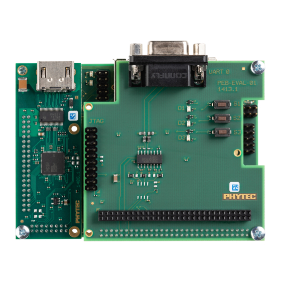
Page 19: View Of The Phyboard-Wega Am335X
Introduction 1.1.3 View of the phyBOARD-Wega AM335x Figure 2: View of the phyBOARD-Wega AM335x © PHYTEC Messtechnik GmbH 2014 L-792e_1... -
Page 20: Software Overview
The Yocto Project is an open source collaboration to create custom Linux-based systems for embedded products regardless of the hardware architecture. We use the Yocto Project to create the Board Support Package (BSP) for our hardware. © PHYTEC Messtechnik GmbH 2014 L-792e_1... -
Page 21: Application Programming
After that, you will copy and execute the newly created program on the target. 2.1.1.1 Work with the Demo Project Click the Eclipse icon to start the application. You can find this icon on your desktop. © PHYTEC Messtechnik GmbH 2014 L-792e_1... - Page 22 AM335x [PB-00802-xxx] Confirm the workspace directory with OK. Now you can see the Eclipse workbench. © PHYTEC Messtechnik GmbH 2014 L-792e_1...
- Page 23 Getting Started First we will import an existing project. Select File ► Import from the menu bar. Expand General and select Existing Projects into Workspace. Click Next. © PHYTEC Messtechnik GmbH 2014 L-792e_1...
- Page 24 AM335x [PB-00802-xxx] Select Browse. Double-click the HelloWorld directory under /opt/prj_workspace/Eclipse/. Click OK. © PHYTEC Messtechnik GmbH 2014 L-792e_1...
- Page 25 The HelloWorld program will be compiled and the HelloWorld executable is built for the target. Then the HelloWorld file is copied to the target using secure copy. After the file has been copied to the target, the program is executed on the target using SSH. © PHYTEC Messtechnik GmbH 2014 L-792e_1...
- Page 26 You have successfully passed the first steps with the Eclipse IDE. You are now able to import existing projects into the Eclipse workspace. You can compile an existing project and execute the program on the target. © PHYTEC Messtechnik GmbH 2014 L-792e_1...
-
Page 27: Creating A New Project
GNU C/C++ cross development toolchain. Open Eclipse if it is not already opened. Select File ► New ► Project from the menu bar. A new dialog opens. Select C Project and click Next. © PHYTEC Messtechnik GmbH 2014 L-792e_1... - Page 28 AM335x [PB-00802-xxx] Enter the project name and click Next. myHelloWorld Click Finish. © PHYTEC Messtechnik GmbH 2014 L-792e_1...
- Page 29 To compile your project for the phyCORE-AM335x instead, you will have to use the GNU C/C++ cross compiler. Right-click the myHelloWorld project and choose Properties. The Properties dialog appears. Select C/C++ Build ► Settings. Select GCC C Compiler. Enter into the Command input field. ${CC} © PHYTEC Messtechnik GmbH 2014 L-792e_1...
- Page 30 AM335x [PB-00802-xxx] Select GCC C Linker. Enter into the Command input field and add in the Command line ${CC} ${LDFLAGS} pattern after ${COMMAND}. © PHYTEC Messtechnik GmbH 2014 L-792e_1...
- Page 31 Getting Started Select GCC Assembler. Change the Command input field to ${AS} Click Apply. Select the Build Steps tab. © PHYTEC Messtechnik GmbH 2014 L-792e_1...
- Page 32 Be sure to enter the semicolon before the ssh command. Ensure that the file myHelloWorld on the target will have execution rights, because otherwise ssh will fail. Click Apply. Click OK. Select Project ► Clean from the menu bar. © PHYTEC Messtechnik GmbH 2014 L-792e_1...
- Page 33 If no errors occur while building the project, you will see a similar output: You have successfully created your first own project with the Eclipse IDE. You have configured the project to create an application for your target platform. © PHYTEC Messtechnik GmbH 2014 L-792e_1...
-
Page 34: Modifying The Demo Application
out = open ("/dev/console", O_RDWR); write(out, buffer, count); close(out); } Enter the following two lines in the main() function to declare the buffer and call the write_tty() function: char buf [] = { "Welcome to the World of PHYTEC! (serial)\n" }; write_tty(buf, sizeof (buf) ‐ 1); In the next screenshot you can see the complete program. © PHYTEC Messtechnik GmbH 2014 L-792e_1... - Page 35 Getting Started Save your program after changing the code. The application will be compiled, built, copied to the target and executed. Click the Microcom icon on the desktop. © PHYTEC Messtechnik GmbH 2014 L-792e_1...
- Page 36 Type to start the application. ./myHelloWorld You will see the following output: .Welcome to the World of PHYTEC! (serial). .Welcome to the World of PHYTEC!... Close Microcom. When you start the application via an SSH session, you only see one output line. When you execute the program with Microcom, you see two output lines.
-
Page 37: Starting A Program Out Of Eclipse On The Target
Select Run ► External Tools ► External Tools Configurations from the menu bar. Double-Click Program a new program configuration will be opened. © PHYTEC Messtechnik GmbH 2014 L-792e_1... - Page 38 AM335x [PB-00802-xxx] In the Name input field, enter: myHelloWorld Target Enter in the Location input field. /usr/bin/ssh Enter into the Arguments field. root@192.168.3.11 ./myHelloWorld Select Apply. © PHYTEC Messtechnik GmbH 2014 L-792e_1...
-
Page 39: Debugging An Example Project
GDB client and GDB server can communicate over a TCP/IP network connection as well as via a serial interface. In this Application Guide we will only describe debugging via TCP/IP. © PHYTEC Messtechnik GmbH 2014 L-792e_1... -
Page 40: Starting The Gdb Server On The Target
GDB server on the target. Start Eclipse if the application is not started yet. Right-click on the myHelloWorld project in the Navigator window. Select Debug As ► Debug Configurations. A dialog to create, manage and run applications appears. © PHYTEC Messtechnik GmbH 2014 L-792e_1... - Page 41 Getting Started Select myHelloWorld under C/C++ Application (to expand it double click on it). Select the Debugger tab. © PHYTEC Messtechnik GmbH 2014 L-792e_1...
- Page 42 AM335x [PB-00802-xxx] Select gdbserver Debugger from the Debugger drop-down box. Enter in the GDB Debugger field ${GDB} Keep the GDB command file field empty. © PHYTEC Messtechnik GmbH 2014 L-792e_1...
- Page 43 (the target's IP address) in the Host name input field. 192.168.3.11 The host's GDB will connect to this IP address to communicate with the target's GDB server. Click Apply. Click Debug. A new dialog appears. •Select Yes to switch to the Debug perspective. © PHYTEC Messtechnik GmbH 2014 L-792e_1...
- Page 44 You have configured your project for remote debugging. You have started the GNU debugger in Eclipse and connected the host's GDB with the target's GDB server. You can now start to debug the project. © PHYTEC Messtechnik GmbH 2014 L-792e_1...
-
Page 45: Setting A Breakpoint
If you resume the application, the debugger will stop at this line. Select the last line in main(). Right-click into the small grey border on the left-hand side and select Toggle Breakpoint to set a new breakpoint. © PHYTEC Messtechnik GmbH 2014 L-792e_1... -
Page 46: Stepping Through And Watching Variable Contents
Expand buf in the Variables window. Click the Step Over button in the Debug window to step to the next line. You will see the content of the buf variable in the Variables window. © PHYTEC Messtechnik GmbH 2014 L-792e_1... - Page 47 Getting Started Click on the variable buf. Then click the button Step into to enter the function write_tty(). The debugger stops in write_tty(). You will see the following variable window: © PHYTEC Messtechnik GmbH 2014 L-792e_1...
-
Page 48: Stepping Through And Changing Variable Contents
Open Microcom if the application is not already opened. Go back to Eclipse. Click the Step Over button twice. Switch to Microcom. Because we changed the count variable to 7 only the first seven characters (Welcome) are displayed in the Microcom console. © PHYTEC Messtechnik GmbH 2014 L-792e_1... -
Page 49: Using The Memory Monitor
Click + Add Memory Monitor. Enter the address of the buffer and click OK. Remember that the variable's address might be different on your system. Change the size of the window. Click Add Rendering. © PHYTEC Messtechnik GmbH 2014 L-792e_1... - Page 50 You can see the contents of the variable buffer at address 0xbef9ec47 (or at the specific address used on your system). Now click the Resume button from the menu bar. The debugger stops at the breakpoint in the last line of main(). © PHYTEC Messtechnik GmbH 2014 L-792e_1...
- Page 51 Eclipse for remote debugging. You can step through a project, watch and change the content of variables, and you can use the memory monitor to view the content at a memory address. © PHYTEC Messtechnik GmbH 2014 L-792e_1...
-
Page 52: Working With Qt Creator
We start with opening the Qt Creator in a terminal, because otherwise the correct environment of the toolchain is not set. Open a terminal. Enter the following command in the terminal to start Qt Creator /usr/bin/qtcreator.sh & © PHYTEC Messtechnik GmbH 2014 L-792e_1... - Page 53 The user interface of Qt Creator appears: Now we import the example project by clicking Open Project. This opens a dialog in which the path to /opt/prj_workspace/Qt is set automatically. Double-click on the HelloWidget folder. Select HelloWidget.pro and click Open. © PHYTEC Messtechnik GmbH 2014 L-792e_1...
-
Page 54: Work With The Demo Application
Our example project is a simple Qt Widget Application. First we take a look at the user interface of our example: Expand the folder Forms under the project sidebar on the left side and double-click mainwindow.ui. © PHYTEC Messtechnik GmbH 2014 L-792e_1... - Page 55 Qt Creator opens the design mode and you can see the design of our project, which has a menu bar with an exit action under the menu item miniQT, one label and three buttons including one with the PHYTEC logo inside. Right-click the “Hide Logo” button and select Go to slot … from the context menu.
- Page 56 Now Qt Creator jumps into the mainwindow.cpp where you can find the definition of the function on_btn_hideLogo_clicked(). You see that clicking this button changes the status of the btn_Logo button from visible to hidden. Next we build and run the example. © PHYTEC Messtechnik GmbH 2014 L-792e_1...
-
Page 57: Compile And Run The Demo Application On The Target
Qt applications on the target. With only one click the project will be built, deployed to the target and executed. Click the green filled triangle near the bottom of the gray bar on the left. © PHYTEC Messtechnik GmbH 2014 L-792e_1... - Page 58 On the connected display you will see the HelloWidget application. Click the big button with the PHYTEC logo to enable and disable the Welcome label. To see the different build steps click Compile output which can be found in the bottom menu bar.
-
Page 59: Compile And Run The Demo Application On The Host
To change the target for downloading and running the application do the following steps: In the gray bar on the left click the button with the small phyBOARD-Wega picture. In the opened context menu select Desktop as Kit and Release as Build. © PHYTEC Messtechnik GmbH 2014 L-792e_1... -
Page 60: Debugging The Demo Application
To make use of the QDebug functions QDebug is already included in the header of the file mainwindow.cpp. In this file you will also see two out-commented lines in the function on_btn_showLogo_clicked() which start with a qDebug() command. This is an example how to make use of qDebug(). © PHYTEC Messtechnik GmbH 2014 L-792e_1... - Page 61 Now the logo was hidden before we pressed the Show Logo button again and we see the appropriate message from qDebug() in the Application Output. QDebug is a simple way to generate debug information. In the next chapter we use the debugger integrated in Qt Creator. © PHYTEC Messtechnik GmbH 2014 L-792e_1...
-
Page 62: Using The Integrated Qt Creator Debugger
The next step is to change the build configuration from Release to Debug. In the gray bar on the left click the button with the small Desktop icon. In the opened context menu select phyBOARD-Wega as Kit and Debug as Build. © PHYTEC Messtechnik GmbH 2014 L-792e_1... - Page 63 Start Debugging by clicking on the green filled triangle with the small magnifier. The debugger starts and Qt Creator changes his view to the Debug mode. The demo application is shown on the connected display. In the running demo application click on the Hide Logo button. © PHYTEC Messtechnik GmbH 2014 L-792e_1...
- Page 64 When the button is pressed the debugger stops at the created breakpoint, because the function is called. You can now watch the stack or the Locals and Expressions. Step into the setVisible function by pressing the Step Into button. Now the definition of this function is opened. © PHYTEC Messtechnik GmbH 2014 L-792e_1...
- Page 65 Continue the stopped application by clicking on Continue. Now the demo application is continued and waiting for user interactions. Stop the Debugger by pressing Stop Debugger. You have successfully finished our short introduction to the Debugger from Qt Creator. © PHYTEC Messtechnik GmbH 2014 L-792e_1...
- Page 66 If your project is more complex, or if you crave more information about working with the BSP, continue with chapter Chapter 4ff includes step by step instructions on how to modify and download the BSP using Yocto. They also include system level information phyBOARD-Wega AM335x. © PHYTEC Messtechnik GmbH 2014 L-792e_1...
-
Page 67: Accessing The Phyboard-Wega Features
Accessing the phyBOARD-Wega Interfaces Accessing the phyBOARD-Wega Features PHYTEC phyBOARD-Wega is fully equipped with all mechanical and electrical components necessary for the speedy and secure start-up. 3.1 Overview of the phyBOARD-Wega Peripherals The phyBOARD-Wega is depicted in Figure 2. It features many different interfaces and is... -
Page 68: Leds
Figure 2 shows the location of the switches. Their function is listed in the table below: Switch Description Section Reset Button 3.2.9 Boot Switch 3.2.8 Table 4: phyBOARD-Wega Switches Description © PHYTEC Messtechnik GmbH 2014 L-792e_1... -
Page 69: Jumpers
Figure 2 shows the location of jumper JP3. Switch Description Section CAN Termination 3.2.6 Table 5: phyBOARD-Wega Jumper Description Detailed descriptions of the assembled connectors, jumpers and switches can be found in the following chapters. © PHYTEC Messtechnik GmbH 2014 L-792e_1... -
Page 70: Functional Components On The Phyboard-Wega Sbc
WAGO male header 6-pole PHOENIX MINI COMBICON base strip Figure 3: Power Supply Connectors © PHYTEC Messtechnik GmbH 2014 L-792e_1... -
Page 71: Phoenix 2-Pole Mini Combicon Base Strip (X67)
Higher and wider operate range of the input voltage • External scaling potential to optimize the electrical output current, by use of customized power modules which match the requirements • 5 V, 3.3 V and backlight power supply © PHYTEC Messtechnik GmbH 2014 L-792e_1... -
Page 72: Power Led D58
VBAT_IN_4RTC (A2) of the phyCORE-AM335x and supplies the RTC and some critical registers of the Power Management IC when the primary system power, VCC5V_IN, is removed. The backup supply lasts approximately 17 ½ days. © PHYTEC Messtechnik GmbH 2014 L-792e_1... -
Page 73: Uart Connectivity (X66 And X69)
Table 8 shows the signal mapping of the RS-232 level signals at connector X66. Figure 4: RS-232 Interface Connector (X66) Signal Signal UART1_RXD_RS232 UART1_RTS_RS232 UART1_TXD_RS232 UART1_CTS_RS232 Table 8: Pin Assignment of RS-232 Interface Connector X66 © PHYTEC Messtechnik GmbH 2014 L-792e_1... -
Page 74: Software Implementation
Only /dev/ttyO0 for UART0 and /dev/ttyO1 for UART1 have been implemented within the BSP. The standard console UART0 is accessible as /dev/ttyO0 and is mainly used for debugging and control of software updates. UART1 can be accessed as /dev/ttyO1. It is intended for user applications. © PHYTEC Messtechnik GmbH 2014 L-792e_1... -
Page 75: Ethernet Connectivity (X16 And X17)
HP Auto-MDIX, eliminating the need for the consideration of a direct connect LAN cable, or a cross-over path cable. They detect the TX and RX pins of the connected device and automatically configure the PHY TX and RX pins accordingly. © PHYTEC Messtechnik GmbH 2014 L-792e_1... -
Page 76: Software Implementation
LED D8 displays the status of USB0_VBUS and LED D7 the status of USB1_VBUS. Numerous jumpers allow to configure the USB interfaces according to your needs. Please refer to section 4.6.1 for more information. © PHYTEC Messtechnik GmbH 2014 L-792e_1... -
Page 77: Software Implementation
(replace sdc1 by the device the computer really shows): sudo mkfs.vfat /dev/sdc1 Using USB OTG as host is supported by the BSP with the module g_zero, but the BSP does not provide support for using USB OTG as host. © PHYTEC Messtechnik GmbH 2014 L-792e_1... -
Page 78: Audio Interface (X55 And X73)
X_MCASP0_AHCLKX, X_I2S_CLK, X_I2S_FRM, X_I2S_ADC and X_I2S_DAC are routed to the A/V connector X71 (please refer to section 4.6.2 for additional information on the A/V connector). Please refer to the audio codec’s reference manual for additional information regarding the special interface specification. © PHYTEC Messtechnik GmbH 2014 L-792e_1... -
Page 79: Software Implementation
You have either mono or stereo gain controls for all the mix points. "MM" means the feature is muted, which can be toggled by hitting m. © PHYTEC Messtechnik GmbH 2014 L-792e_1... -
Page 80: Can Connectivity (X65, Jp3)
Figure 9: Components supporting the CAN Interface Table 11 below shows the signal mapping of the CAN1 signals at connector X65. Signal Signal X_CANL X_CANH Shield Table 11: Pin Assignment of CAN Connector X65 © PHYTEC Messtechnik GmbH 2014 L-792e_1... -
Page 81: Software Implementation
MAC and IP addresses are arbitrary and obsolete. configuration done with systemd configuration file /lib/systemd/system/can0.service. For a persistent change of the default bitrates change the configuration in meta-yogurt/recipes-core/systemd/systemd/can0.service instead and rebuild the root filesystem. © PHYTEC Messtechnik GmbH 2014 L-792e_1... - Page 82 Number of Received Bytes TX bytes Number of Transmitted Bytes errors... Bus Error Statistics You can send messages with cansend or receive messages with candump: cansend can0 123#45.67 candump can0 messages for further information about using cansend ‐‐help candump ‐‐help and options. © PHYTEC Messtechnik GmbH 2014 L-792e_1...
-
Page 83: Secure Digital Memory Card/ Multimedia Card (X11)
(”hard disk” like handling). If it does not contain one, the whole device can be used for a file system (”floppy” like handling). In this case /dev/mmcblk0 must be used for formatting and mounting. © PHYTEC Messtechnik GmbH 2014 L-792e_1... -
Page 84: Boot Mode (S4)
SYSBOOT[4:0] = 10011b → NAND, NANDI2C, MMC0, UART0 Boot mode 1 (S4 = OFF) SYSBOOT[4:0] = 10111b → MMC0, SPI0, UART0, USB Boot mode 2 (S4 = ON) Table 12: Boot Switch Configuration (S4) © PHYTEC Messtechnik GmbH 2014 L-792e_1... -
Page 85: System Reset Button (S2)
For further information of the expansion connector and the pinout see chapter 4.6.4. Information on the expansion boards available for the expansion connector can be found in the Application Guide for phyBOARD-Wega Expansion Boards (L-793e). © PHYTEC Messtechnik GmbH 2014 L-792e_1... -
Page 86: Addressing The Rtc
Asking for the current frequency is done with: cat /sys/devices/system/cpu/cpu0/cpufreq/scaling_cur_freq So called governors are selecting one of these frequencies in accordance to their goals, automatically. The governors available can be listed with the following command: cat /sys/devices/system/cpu/cpu0/cpufreq/scaling_available_governors © PHYTEC Messtechnik GmbH 2014 L-792e_1... - Page 87 In order to ask for the current governor, type cat /sys/devices/system/cpu/cpu0/cpufreq/scaling_governor and you will normally get: ondemand. Switching over to another governor (e.g. userspace) is done with: echo userspace > /sys/devices/system/cpu/cpu0/cpufreq/scaling_governor For more detailed information about the govenors refer to the Linux kernel documentation Documentation/cpu-freq/governors.txt. © PHYTEC Messtechnik GmbH 2014 L-792e_1...
-
Page 88: Using The Pre-Installed Qt Demo Applications
HDMI monitor requires an USB mouse connected to the board in order to test the demos. By default the demo will be started automatically after booting (see section 2.2.1 information how to stop the demo, or how to remove it from the autostart). © PHYTEC Messtechnik GmbH 2014 L-792e_1... -
Page 89: System Level Customizing
In this chapter of the Application Guide we describe only the basic Yocto usage. For in-depth explanations refer to the Yocto Reference Manual. In this part you will learn how to use the Yocto Project and the Phytec BSP. You can find the pre-build BSP in the virtual machine under /opt/PHYTEC_BSPs/phyBOARD-WEGA/. All necessary tools and programs are already pre-installed to directly start with Yocto. - Page 90 Before we add the package we check if the right configuration is set. Open the configuration file with any editor, e.g. VI, with the following command: vi conf/local.conf Check the MACHINE variable in this file. © PHYTEC Messtechnik GmbH 2014 L-792e_1...
- Page 91 In the same file we can add nano by adding the following line at the end of the file (as shown in the previous picture): IMAGE_INSTALL_append = “ nano” Save the changes and close the file with :x and Enter. © PHYTEC Messtechnik GmbH 2014 L-792e_1...
- Page 92 If the package is also missing on our ftp-server, please send an email to support@phytec.de. We will then take it from our build-server and upload it onto our ftp-server for you. Among other images you will find the kernel named zImage, the device tree named zImage- am335x-wega-rdk.dtb and the root file system named phytec-qt5demo-image-phyboard-...
-
Page 93: Writing The Root Filesystem Into The Target's Flash
First open a new terminal window if it is not opened yet. Then change to the directory /opt/PHYTEC_BSPs/phyBOARD-WEGA/build/deploy/images/phyboard-wega-am335x-1/ Open Microcom and press the RESET button on the target. You will see the output .Hit any key to stop autoboot.. Press any key to stop autoboot. © PHYTEC Messtechnik GmbH 2014 L-792e_1... - Page 94 After the target has successfully finished booting, type to log in. root Now we can test the newly installed editor nano by trying to open a file with it. © PHYTEC Messtechnik GmbH 2014 L-792e_1...
- Page 95 In this section you learned how to prepare the partition of the root filesystem and how to download the root filesystem from a TFTP server into the flash of the target. © PHYTEC Messtechnik GmbH 2014 L-792e_1...
-
Page 96: Updating The Software Using An Sd Card
Get the correct device name with or from the last outputs of sudo fdisk –l dmesg after inserting the SD card. Now use the following command to create your bootable SD card: sudo dd if=phytec‐qt5demo‐image‐phywega‐am335x‐*.sdcard of=/dev/<DEVICE> © PHYTEC Messtechnik GmbH 2014 L-792e_1... -
Page 97: Flashing The Bootloader
4.4.3 Writing the Kernel / Root File System into Flash Flash the Linux kernel by typing: erase /dev/nand0.kernel.bb cp /boot/linuximage /dev/nand0.kernel.bb Flash the Oftree by typing: erase /dev/nand0.oftree.bb cp /boot/oftree /dev/nand0.oftree.bb Write the root file system into the Flash by typing: ubiformat /dev/nand0.root ubiattach /dev/nand0.root ubimkvol /dev/ubi0 root 0 cp /boot/root.ubifs /dev/ubi0.root © PHYTEC Messtechnik GmbH 2014 L-792e_1... -
Page 98: Setup Your Own Linux Host Pc
14.04.2 64-bit, which we use, can be downloaded from www.ubuntu.com We recommend to have at least 80 GB of free disk space available to install all required packages. Boot Ubuntu from the created bootable medium. Select Install Ubuntu in the first Welcome window. © PHYTEC Messtechnik GmbH 2014 L-792e_1... - Page 99 Advanced Information The Preparing to install Ubuntu… window appears. From Ubuntu it is advised that you select Download updates while installing and Install this third-party software now. © PHYTEC Messtechnik GmbH 2014 L-792e_1...
-
Page 100: Installation Of Software Packages
The first preparations are completed. In the next sections you will proceed with building the Board Support Package installation of Eclipse and Qt Creator and the set up of the TFTP server. © PHYTEC Messtechnik GmbH 2014 L-792e_1... -
Page 101: Set The Git Configuration
The phyLinux script is a basic management tool for PHYTEC Yocto BSP releases. It is mainly a tool to get started with the BSP structure. You can get all the BSP sources without the need of interacting with repo or git. -
Page 102: Setting Up Eclipse And Integrate Plug-Ins
First of all you have to create a workspace folder, in which you can save your Eclipse projects. In this example we create the workspace in the /opt/ directory as it is in the virtual machine: mkdir –p /opt/prj_workspace/Eclipse © PHYTEC Messtechnik GmbH 2014 L-792e_1... - Page 103 Enter the path to the workspace created: /opt/prj_workspace/Eclipse After Eclipse has started click Help in the menu bar and then Install new Software. A window opens to add a plug-in to Eclipse. © PHYTEC Messtechnik GmbH 2014 L-792e_1...
- Page 104 AM335x [PB-00802-xxx] In the drop-down menu Work with select Indigo Update Site. The available plug-ins appear in the selection area below now. Expand Programming Languages and check C/C++ Development Tools. Click Next. © PHYTEC Messtechnik GmbH 2014 L-792e_1...
-
Page 105: Install And Setup Qt Creator
Set execute priviliges: sudo chmod +x qt‐opensource‐linux‐x64‐5.3.2.run Run the QtCreator installation routine ./qt‐opensource‐linux‐x64‐5.3.2.run This opens a window for the installation. Step trough the installation and if you are asked set following installation directory: /opt/x64_Qt5.3.2 © PHYTEC Messtechnik GmbH 2014 L-792e_1... - Page 106 In the Select Components window keep the default selection of the components and click Next. Proceed trough the license agreement and start the installation. After the installation is finished make a symbolic link to easy start Qt Creator: sudo ln ‐s /opt/x64_Qt5.3.2/Tools/QtCreator/bin/qtcreator.sh /usr/bin/qtcreator.sh © PHYTEC Messtechnik GmbH 2014 L-792e_1...
- Page 107 Start Qt Creator with the following command in a terminal: /usr/bin/qtcreator.sh Add the phyBOARD-Wega as device with following inputs by opening Tools --> Options --> Devices --> Add--> Generic Linux Device: Name: phyBOARD-Wega 192.168.3.11 Username: root Keep the password empty © PHYTEC Messtechnik GmbH 2014 L-792e_1...
- Page 108 Set the project directory and build directory Tools --> Options --> Build & Run --> General. Projects Directory ‐‐> Directory: /opt/prj_workspace/Qt Change the beginning of the Default build directory: ../build/%{CurrentProject:Name} Select tab Qt Versions and click Add… to add a new one. Name: AM335x_Qt5.3.2 qmake Location: /opt/yogurt/AM335x‐PD15.1.1/sysroots/x86_64‐yogurtsdk‐ linux/usr/bin/qt5/qmake © PHYTEC Messtechnik GmbH 2014 L-792e_1...
- Page 109 Advanced Information Select tab Compilers and click on Add select GCC Name: arm‐gcc Path:/opt/yogurt/AM335x‐PD15.1.1/sysroots/x86_64‐yogurtsdk‐ linux/usr/bin/arm‐phytec‐linux‐gnueabi/arm‐phytec‐linux‐gnueabi‐gcc Select tab Debuggers an click on Add Name: arm‐gdb Path: :/opt/yogurt/AM335x‐PD15.1.1/sysroots/x86_64‐yogurtsdk‐ linux/usr/bin/arm‐phytec‐linux‐gnueabi/arm‐phytec‐linux‐gnueabi‐gdb © PHYTEC Messtechnik GmbH 2014 L-792e_1...
-
Page 110: Setting Up A Tftp Server
First change the file /etc/default/tftp-hpa as follows: TFTP_USERNAME="tftp" TFTP_DIRECTORY="/tftpboot" TFTP_ADDRESS="0.0.0.0:69" TFTP_OPTIONS="‐‐secure" Then create a folder called /tftpboot. The TFTP server will access this folder later. mkdir /tftpboot Finally we have to set the right permissions: chmod 777 /tftpboot © PHYTEC Messtechnik GmbH 2014 L-792e_1... -
Page 111: Optional Settings
Also there are some scripts that will be executed at the first start after the installation. These scripts ensure that the right permissions are set for the created user. Congratulations! You have successfully configured your Ubuntu to work with. © PHYTEC Messtechnik GmbH 2014 L-792e_1... -
Page 112: System Level Hardware Information
Separate OC signals for USB1 (nUSB1_OC_GPIO3_18) and USB0 (nUSB0_OC_GPIO3_19) One OC signal (nUSB1_OC_GPIO3_18)for both USB interfaces Table 13: USBOC Configuration If J78 is set to 1+2, J77 also has to be set to 1+2. 4.6.1.2 © PHYTEC Messtechnik GmbH 2014 L-792e_1... -
Page 113: Rerouting The Usb Interfaces To Different Connectors (J72 - J75, J79 And J80)
Caution! The voltage level of the USB ID signal X_USB_ID_EXP, is 1.8 V. Steady state voltages above 2.1 V applied to this signal may damage the AM335x. Note: The ID pin of USB1 is hardwired. To use the function at the expansion connector R399 must be removed, too. © PHYTEC Messtechnik GmbH 2014 L-792e_1... -
Page 114: Software Implementation
To program the character devices i2cset i2cdump /dev/i2c-* directly see the kernel documentation in Documentation/i2c/dev-interface. 4.6.2.1.1 EEPROM It is possible to read/write directly to the device: /sys/class/i2c‐adapter/i2c‐0/0‐0052/eeprom e.g.: Fill with zeros dd if=/dev/zero of=/sys/class/i2c‐adapter/i2c‐0/0‐0052/eeprom bs=4096 count=1 © PHYTEC Messtechnik GmbH 2014 L-792e_1... -
Page 115: Audio/Video Connectors (X70 And X71)
The A/V connector is intended for use with phyBOARD Expansion Boards , and to add specific audio/video connectivity with custom expansion boards. Figure 14: Audio/Video Connectors (X70 and X71) Please find additional information on phyBOARD-Wega AM335x Expansion Boards in the corresponding application guide (L-793e). © PHYTEC Messtechnik GmbH 2014 L-792e_1... - Page 116 X_LCD_D14 3.3 V LCD D14 X_LCD_D15 3.3 V LCD D15 Ground X_LCD_PCLK 3.3 V LCD Pixel Clock X_LCD_BIAS_EN 3.3 V LCD BIAS X_LCD_HSYNC 3.3 V LCD Horizontal Synchronization X_LCD_VSYNC 3.3 V LCD Vertical Synchronization © PHYTEC Messtechnik GmbH 2014 L-792e_1...
-
Page 117: Table 17: Pin Assignment Of Phytec A/V Connector X70
X_PWM1_OUT 3.3 V Pulse Width Modulation VCC_BL Backlight power supply VCC5V 5.0 V 5 V power supply Table 17: Pin Assignment of PHYTEC A/V connector X70 Pin # Signal Name Type Description X_I2S_CLK 3.3 V I²S Clock X_I2S_FRM 3.3 V I²S Frame I²S Analog-Digital converter... -
Page 118: Software Implementation
If J77 is set to 2+3, J78 also has to be set to 2+3. 4.6.3.1 Software Implementation 4.6.3.1.1 Framebuffer The framebuffer driver gains access to the display via device node /dev/fb0 for PHYTEC display connector. A simple test of the framebuffer feature can then be run with: fbtest ... -
Page 119: I C Connectivity
Comment Usage GPIO1_30 GPIO3_19 or 115 or selectable with jumper J77 GPIO3_21 Table 20: GPIOs available at A/V Connector X71 Please refer to chapter 4.6.4.1.5 for information on how to use the GPIO pins. © PHYTEC Messtechnik GmbH 2014 L-792e_1... -
Page 120: Expansion Connector (X69)
, and to add specific functions with custom expansion boards The pinout of the expansion connector is shown in the following table. Please find additional information on phyBOARD-Wega AM335x Expansion Boards in the corresponding application guide (L-793e). © PHYTEC Messtechnik GmbH 2014 L-792e_1... - Page 121 3.3 V MMC data 1 Ground X_MMC2_DAT2 3.3 V MMC data 2 X_UART2_RX_GPIO3_9 3.3 V UART 2 receive data; GPIO3_9 X_MMC2_DAT3 3.3 V MMC data 3 X_UART2_TX_GPIO3_10 3.3 V UART 2 transmit data; GPIO3_10 Ground © PHYTEC Messtechnik GmbH 2014 L-792e_1...
-
Page 122: Table 21: Pin Assignment Of Phytec Expansion Connector X69
5.0 V 5 V input supply voltage Table 21: Pin Assignment of PHYTEC Expansion Connector X69 These pins are configured as GPIO pins. To use them as UART interface the pin muxing must be changed and additional software development is required. -
Page 123: Software Implementation
These drivers might be helpful for you even though they are usually not tested. If you really want to access SPI from userland, you can use SPIDEV in the linux kernel. See the kernel documentation in Documentation/spi/spidev. © PHYTEC Messtechnik GmbH 2014 L-792e_1... -
Page 124: I C Connectivity
GPIOs available at Expansion Connector X69 To use the GPIOs switch to the appropriate directory by entering cd /sys/class/gpio Then you must request the GPIO from the kernel and export the control to userspace by typing echo GPIOno > export © PHYTEC Messtechnik GmbH 2014 L-792e_1... -
Page 125: Gpo Pins And Device Path
Pin # Signal Name Path /sys/class/leds/user_led_green GPIO3_9 /sys/class/leds/user_led_red GPIO2_18 /sys/class/leds/user_led_yellow GPIO2_19 Table 23: GPO Pins and Device Path and enter: for a high level at the pin, and echo 255 > brightness for a low level at the pin echo 0 > brightness © PHYTEC Messtechnik GmbH 2014 L-792e_1... -
Page 126: Revision History
Preliminary edition. L-792e_0 Describes the phyBOARD-Wega AM335x SOM (PCB 1397.0) with phyBOARD-Wega- Carrier Board (PCB 1405.0). 12.08.2015 Manual First edition. L-792e_1 Describes the phyBOARD-Wega AM335x SOM (PCB 1397.0) with phyBOARD-Wega- Carrier Board (PCB 1405.1). © PHYTEC Messtechnik GmbH 2014 L-792e_1... -
Page 127: Index
X65........... 64 Jumpers ..........53 X66........... 57 X67........... 54 LEDs ..........52 X69..........57, 69 D58..........56 X70..........69, 99 D7 60 X71..........69, 99 D8 60 X72........... 54 LINK LED..........59 X73........... 62 © PHYTEC Messtechnik GmbH 2014 L-792e_1... - Page 128 AM335x [PB-00802-xxx] © PHYTEC Messtechnik GmbH 2014 L-792e_1...
- Page 129 How would you improve this manual? Did you find any mistakes in this manual? page Submitted by: Customer number Name: Company: Address: Return to: PHYTEC Messtechnik GmbH Postfach 100403 D-55135 Mainz, Germany Fax : +49 (6131) 9221-33 © PHYTEC Messtechnik GmbH 2014 L-792e_1...
- Page 130 Published by © PHYTEC Messtechnik GmbH 2014 Ordering No. L-792e_1 Printed in Germany...
Need help?
Do you have a question about the phyBoard Wega AM335x and is the answer not in the manual?
Questions and answers