Sign In
Upload
Manuals
Brands
Phytec Manuals
Single board computers
phyCORE-OMAP4430
Phytec phyCORE-OMAP4430 System on Module Manuals
Manuals and User Guides for Phytec phyCORE-OMAP4430 System on Module. We have
1
Phytec phyCORE-OMAP4430 System on Module manual available for free PDF download: Hardware Manual
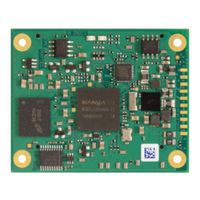
Phytec phyCORE-OMAP4430 Hardware Manual (168 pages)
Brand:
Phytec
| Category:
Single board computers
| Size: 13 MB
Table of Contents
Table of Contents
3
Conventions, Abbreviations and Acronyms
13
Table 1: Abbreviations and Acronyms Used in this Manual
13
Preface
15
1 Part I: PCM-049/Phycore-Omap44Xx System on Module
21
Introduction
23
1Block Diagram
25
Figure 1: Block Diagram of the Phycore-Omap44Xx
25
2View of the Phycore-Omap44Xx
26
Figure 2: Top View of the Phycore-Omap44Xx (Controller Side)
26
Figure 3: Bottom View of the Phycore-Omap44Xx (Connector Side)
27
3Minimum Requirements to Operate the Phycore-Omap44Xx
28
Pin Description
29
Figure 4: Pin-Out of the Phycore-Connector (Top View, with Cross Section Insert)
30
Table 2: Pin-Out of the Phycore-Connector X1, Row a
31
Table 3: Pin-Out of the Phycore-Connector X1, Row B
33
Table 4: Pin-Out of the Phycore-Connector X1, Row C
35
Table 5: Pin-Out of the Phycore-Connector X1, Row D
38
Jumpers
41
Figure 5: Typical Jumper Pad Numbering Scheme
41
Figure 6: Jumper Locations (Top View)
42
Figure 7: Jumper Locations (Bottom View)
43
Table 6: Phycore-Omap44Xx Jumper Settings
44
Power
47
1Primary System Power (VCC_3V3_IN)
47
2Backup Voltage (VBAT)
47
3Power Management IC (U5)
48
Power Domains
48
Figure 8: Power Supply Diagram
49
Power Management
50
Real Time Clock (RTC)
50
Table 7: Power Management Signals
50
External Battery Charging
51
Table 8: Location of External Charger Signals
51
Voltage Level and Current Consumption Measuring
51
4Reference Voltages
52
System Configuration and Booting
53
Table 9: Boot Modes of the Phycore-Omap44Xx (Memory Type Devices Preferred)
54
Table 10: Boot Modes of the Phycore-Omap44Xx (Peripheral Type Devices Preferred)
54
System Memory
55
1LPDDR2-SDRAM (U1, Pop Memory)
55
2NAND Flash Memory (U4)
56
NAND Flash Lock Control (J4)
56
Table 11: Compatible NAND Flash Devices
56
Table 12: NAND Flash Lock Control Via J4
56
3I2C Eeprom (U2)
57
EEPROM Write Protection Control (J5)
57
Setting the EEPROM Lower Address Bits (J1, J2, J3)
57
Table 13: U2 EEPROM I2C Address Via J1, J2, and J3
57
Table 14: EEPROM Write Protection States Via J5
57
4Memory Model
58
SD / MMC Card Interfaces
59
Table 15: Location of SD/ MMC Card Interface Signals (SDMMC1)
59
Table 16: Location of SD/ MMC Card Interface Signals (SDMMC5)
60
Serial Interfaces
61
1Universal Asynchronous Interface
62
Table 17: Location of the UART Signals
62
2USB OTG Interface
63
3USB Host Transceiver (U8)
63
Table 18: Location of the USB OTG Signals
63
Table 19: Location of the USB Host Signals
63
4Full-Speed IC USB Host Interface
64
5Ethernet Interface
64
Ethernet Controller (U12)
64
Table 20: Location of the IC USB Host Signals
64
Table 21: Location of the Ethernet Signals
64
MAC Address EEPROM (U13)
65
6I2C Interface
66
Table 22: I2C Interface Signal Location
66
Table 23: I2C Addresses in Use
66
7SPI Interface
67
8Multichannel Buffered Serial Port (Mcbsp)
67
Table 24: SPI Interface Signal Location
67
Table 25: Mcbsp Signal Location
67
9Multichannel Audio Serial Port (Mcasp)
68
Table 26: Multichannel Audio Serial Port (Mcasp) Signal Location
68
General Purpose I/Os
69
Table 27: Location of Dedicated GPIO Pins
69
Debug Interface (X7)
71
Table 28: JTAG Connector X7 Signal Assignment
71
Table 29: Location of the JTAG Signals on the Phycore-Connector X1
72
Figure 9: JTAG Interface at X7 (Top View)
73
Figure 10: JTAG Interface at X7 (Bottom View)
74
Display Interfaces
75
1Parallel Display Interface
76
Table 30: Parallel Display Interface Signal Location
76
2MIPI Display Serial Interface (DSI)
77
Table 31: DSI Signal Location
77
3High-Definition Multimedia Interface (HDMI)
78
Table 32: HDMI Signal Location
78
Camera Interfaces
79
Table 33: Camera Interface Control Signal Location
79
1Primary Camera Interface (CSI2-A/CSI21)
80
Table 34: Primary Camera Interface (CSI2-A/CSI21) Signal Location
80
2Secondary Camera Interface (CSI2-B/CSI22)
81
Table 35: Secondary Camera Interface (CSI2-B/CSI22) Signal Location
81
Keyboard Interface
82
Table 36: Keyboard Interface Signal Location
82
User Leds
83
Technical Specifications
85
Figure 11: Physical Dimensions
85
Hints for Integrating and Handling the Phycore-Omap44Xx
87
1Integrating the Phycore-Omap44Xx
87
2Handling the Phycore-Omap44Xx
87
Figure 12: Footprint of the Phycore-Omap44X
88
Component Placement Diagram
89
Figure 13: Phycore-Omap44Xx Component Placement (Top View)
89
Figure 14: Phycore-Omap44Xx Component Placement (Bottom View)
90
2 Part II: PCM-959/Phycore-Omap44Xx Carrier Board
91
Introduction
93
1Concept of the Phycore-Omap44Xx Carrier Board
94
2Overview of the Phycore-Omap44Xx Carrier Board Peripherals
95
Figure 15: Phycore-Omap44Xx Carrier Board Overview of Connectors, Leds and Buttons (Top View)
95
Figure 16: Phycore-Omap44Xx Carrier Board Overview of Connectors, Leds and Buttons (Bottom View)
96
Connectors and Pin Header
97
Table 37: Phycore-Omap44Xx Carrier Board Connectors and Pin Headers
97
Switches
98
Table 38: Phycore-Omap44Xx Carrier Board Push Buttons Descriptions
98
Table 39: Phycore-Omap44Xx Carrier Board DIP-Switch Descriptions
98
Leds
99
Table 40: Phycore-Omap44Xx Carrier Board Leds Descriptions
99
Figure 17: Typical Jumper Numbering Scheme
100
Jumpers
100
Figure 18: Phycore-Omap44Xx Carrier Board Jumper Locations (Top View)
101
Figure 19: Phycore-Omap44Xx Carrier Board Jumper Locations (Bottom View)
102
Table 41: Phycore-Omap44Xx Carrier Board Jumper Settings
107
3Functional Components on the Phycore-Omap44Xx Carrier Board
108
Figure 20: Phycore-Omap44Xx SOM Connectivity to the Carrier Board
108
Phycore-Omap44Xx SOM Connectivity (X22)
108
Table 42: Specifically Used Pins on the Phycore-Connector
109
Figure 21: Powering Scheme
110
Power
110
Table 43: Voltage Domains on the Carrier Board
110
Figure 22: Power Connector Corresponding to Wall Adapter Input X6
111
Table 44: Power Leds
111
Table 45: Power Jumpers
111
Wall Adapter Input (X6)
111
Power over Ethernet (Poe)
112
Current Measurement
113
Power Management
113
Table 46: Resistor Values for Current Measurement
113
Connectivity to Universal Asynchronous Interfaces (P1 + X5)
114
Figure 23: RS-232 Interface Connectors (P1, X5) and Jumpers
114
Figure 24: RS-232 Connector P1 Signal Mapping
114
Connectivity to UART 1 (TTL)
115
Connectivity to UART 2 (RS-232)
115
Connectivity to UART 3 (RS-232)
115
Table 47: Mapping of the UART1 Signals on the Expansion Connector (X5)
115
Table 48: Operation States of the RS-232 Transceiver MAX3380
116
Table 49: Possible Configurations of the MAX3380 RS-232 Transceiver
116
Ethernet Connectivity (X9)
117
Figure 25: Ethernet Interface at Connector X9
117
Figure 26: Components Supporting the USB Host Interface
118
USB Host Connectivity (X8, X12,X18,X19)
118
Table 50: Distribution of the USB Hub's (U7) Ports
119
Figure 27: USB OTG Interface at Connector X7
120
USB OTG Connectivity (X7)
120
Display / Touch Connectivity (X12, X13)
121
Figure 28: Display / Touch Connectivity (X12, X13)(Top View)
121
Figure 29: Display / Touch Connectivity (X12, X13)(Bottom View)
121
PDI Data Connector (X12)
122
Table 51: PDI Display Data Connector X12 Signal Description
123
Table 52: Auxiliary Interfaces at PDI Data Connector X12
125
PDI Power Connector (X13)
126
Table 53: PDI Power Connector X32 Signal Description
126
Touch Screen Connectivity
126
Figure 30: HDMI - DVI Connectivity (X23)
127
HDMI - DVI Connectivity (X23)
127
Table 54: DVI Connector X23
128
Camera Interfaces (X4, X5)
130
Figure 31: Camera Interfaces (Top View)
130
Figure 32: Camera Interfaces (Bottom View)
130
Primary Camera Interface CSI2-A/CSI21 (X5)
131
Table 55: Primary Camera Interface CSI2-A/CSI21 at Expansion Connector X5
131
Secondary Camera Interface CSI2-B/CSI22 (X4)
132
Table 56: CSI2-A/CSI21 Supplementary Signals at Expansion Connector X5
132
Table 57: Secondary Camera Interface CSI-B/CSI22 at Camera Connector X4
133
Camera Auxiliary Connector (X2)
134
Table 58: Camera Auxiliary Connector X2
134
10Audio Connectivity (X5, X14, X15, X17)
136
Figure 33: Components Supporting the Audio Interface at Connectors X5, X14, X15 and X17 (Top View)
136
Figure 34: Components Supporting the Audio Interface at Connectors X5, X14, X15 and X17 (Bottom View)
136
11I2C Connectivity
138
Figure 35: I2C Connectivity (Top View)
138
Figure 36: I2C Connectivity (Bottom View)
138
I2C Connectivity
138
Table 60: I2C Addresses in Use
140
12SPI Connectivity
141
Figure 37: SPI Connectivity
141
13User Programmable Gpios
142
Assignment of the SPI1 Chip Select Signals
142
Figure 38: Gpios at Expansion Connector X5
142
14User Programmable Leds
144
Figure 39: User Programmable Leds
144
User Programmable Leds
144
15Extension Connectors (X18, X19)
145
Figure 40: Extension Connectors X18, X19
145
Table 64: Signal Assignment to Extension Connector
145
Table 65: PHYTEC Extension Connectors X18, X19
146
Figure 43: Boot Mode Selection Switches S1 and S2
149
Table 66: Possible Configurations of the DIP-Switches
150
Table 67: Connections between DIP-Switches S1 / S2 and the Configuration Pins on the Phycore
150
Figure 44: System Reset Button S7
151
Figure 45: Phycore JTAG Connectivity X1
152
Table 68: JTAG Connector X1 Pin Descriptions
153
Figure 46: Keypad Connector X21
154
Table 69: Keypad Connector (X21) Signal Mapping
154
Figure 47: Expansion Connector X5
156
Table 70: Parallel Display Interface (DISPC) Signal Mapping
157
USBB2 Signal Mapping
158
I2C Signal Mapping
159
Table 73: CSI21 Camera Signal Mapping
159
SPI1 Signal Mapping
160
Table 75: SPI2 (Mcasp) Signal Mapping
161
UART1 Signal Mapping
161
Audio Speaker Mapping
162
PMIC Signal Mapping
162
Table 80: System Signal Mapping
162
USBC1 Signal Mapping
162
Power Signal Mapping
163
Signals Freely Available as GPIO
163
Figure 48: Carrier Board Physical Dimensions
165
Advertisement
Advertisement
Related Products
Phytec phyCORE-TC1796
Phytec phyCORE-AM64 Series
Phytec phyCORE-P8xC51Mx2
Phytec phyCORE-XC167
Phytec phyCORE-AM64xx
Phytec phyCORE-i.MX7
Phytec phyCORE-AM65x
Phytec phyCORE-i.MX 91
Phytec phyCORE-i.MX 93
Phytec phyCORE-STM32MP13 Series
Phytec Categories
Computer Hardware
Motherboard
Single board computers
Microcontrollers
Control Unit
More Phytec Manuals
Login
Sign In
OR
Sign in with Facebook
Sign in with Google
Upload manual
Upload from disk
Upload from URL