Table of Contents

Related Manuals for NOVOTEST UD3701

Summary of Contents for NOVOTEST UD3701
- Page 1 Address: 51200, Ukraine, Novomoskovsk, str. Spasskaya, 5 Sales: cell.: +38-067-593-59-77 sales@novotest.biz http://novotest.biz/ Warranty maintenance and service support: cell.: +38-067-593-59-77 Ultrasonic Flaw Detector NOVOTEST UD3701...
-
Page 2: Table Of Contents
Operation manual Ultrasonic Flaw Detector NOVOTEST UD3701 CONTENT GENERAL INFORMATION ........................5 ABBREVIATION USED ......................... 6 1 DESCRIPTION AND OPERATION OF THE DEVICE AND ITS COMPONENTS ......7 1.1 The purpose of the device ....................... 7 1.2 Technical characteristics of the device ................... 7 1.3 Standard delivery set ........................ - Page 3 Operation manual Ultrasonic Flaw Detector NOVOTEST UD3701 2.5.3 Determination of entry angle of the probe ................56 2.5.4 Determination of probe arrow ....................56 2.5.5 Determination of UT waves velocity in the tested object by straight beam probe ....57 2.6 Connecting the device to PC ......................
- Page 4 Ultrasonic Flaw Detector NOVOTEST UD3701 (hereinafter referred to as the device or flaw detector). The document contains technical characteristics, description of the design and principle of operation, as well as information necessary for the correct use of the device.
-
Page 5: General Information
Operation manual Ultrasonic Flaw Detector NOVOTEST UD3701 GENERAL INFORMATION Correct and effective use of flaw detector requires obligatory availability: Technical characteristics of flaw detector comply with requirements of test tasks; Relevant quality-control procedures; Well-qualified operator. Present OM gives operator only instructions about intended use of the device. It does not give understanding about influencing factors while testing and basic principal of ultrasonic. -
Page 6: Abbreviation Used
Operation manual Ultrasonic Flaw Detector NOVOTEST UD3701 ABBREVIATION USED In this OM following abbreviations and symbols are used: DGS – distance–gain-size (defect); DAC – distance amplitude curve; DTC – defect control (automatic signaling of defects); TVG – time varied gain;... -
Page 7: Description And Operation Of The Device And Its Components
(LCD) provides a mapping of ultrasonic signals in the form of A-scan, as well as images of cross sections of testing objects in the form of B-scans. Ultrasonic Flaw Detector NOVOTEST UD3701 has extensional functions of modern professional device: ... - Page 8 Operation manual Ultrasonic Flaw Detector NOVOTEST UD3701 Table 1.2 – Technical characteristics of the device Scan, µs: – minimum 0 – 14 – maximum 0 – 1000 Delay, µs 0 – 1000 Maximum thickness of tested object, mm Up to 6000 (echo-signal) for steel...
-
Page 9: Standard Delivery Set
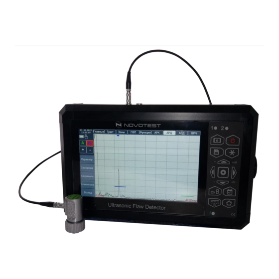
Operation manual Ultrasonic Flaw Detector NOVOTEST UD3701 1.3 Standard delivery set Electronic unit ......................... 1 pc. UT probes: Straight beam probe ......................1 pc. Angle beam probe ......................1 pc. *Type and quantity of probes could be changed or added according to the customer order. - Page 10 (receiver); 3 – colored 7-inch touch screen display; 4 – indicator of А gate; 5 – indicator of B gate; 6 – keyboard; 7 –USB port; 8 – battery indicator. Figure 1.2 – Ultrasonic Flaw Detector NONOTEST UD3701 Table 1.3 – Control keys –...
-
Page 11: Probes
Operation manual Ultrasonic Flaw Detector NOVOTEST UD3701 1.5 Probes Flaw detector is designed to operate with the contact, single and dual element UT probes. The device uses a generator of bipolar sounding pulses with controlled duration, which provides operating with most probes on the market: with integrated terminating inductance and without it. -
Page 12: Design And Functioning
Operation manual Ultrasonic Flaw Detector NOVOTEST UD3701 Figure 1.5 - Appearance of the angle beam single element probe P122 – Angle beam dual element probe These probes mostly are used for NDT of girth welds of pipe elements from steel and polyethylene with 14-219 mm diameter and 2-6 mm thickness. -
Page 13: Design Of The Flaw Detector
Operation manual Ultrasonic Flaw Detector NOVOTEST UD3701 Flaw detector implements shadow, echo and mirror-shadow methods of UT testing. As for structure, flaw detector consists of functional finished blocks (electronic plates). Electronic blocks are connected via detachable sockets (ports) (Figure 1.7). -
Page 14: Device Modes
Operation manual Ultrasonic Flaw Detector NOVOTEST UD3701 1.7 Device modes The device has following modes: 1. «FLAW DETECTOR»; 2. «ARCHIVE»; 3. «RESULTS»; 4. «THICKNESS GAUGE»; 5. «GUIDE»; 6. «SETTINGS»; 7. «INFORMATION». 1.7.1 «FLAW DETECTOR» mode To enter «FLAW DETECTOR» mode, user has, after power-on the device (p. 2.3.2), to select «FLAW DETECTOR»... - Page 15 Operation manual Ultrasonic Flaw Detector NOVOTEST UD3701 1.7.1.1 «Basic» parameters group Measurement settings for «Basic» group are described in details in Table. 1.5. Figure 1.9 shows «Basic» group on display. Table 1.5 – Description of measurement settings for «Basic» group...
- Page 16 Operation manual Ultrasonic Flaw Detector NOVOTEST UD3701 Table 1.6 – Description of measurement settings for «Tract» parameters group Parameters Description Setting of gain for receiver path GAIN Range: from 0 to 126 dB, with steps of 0.1 or 1 dB Scanning time –...
- Page 17 Operation manual Ultrasonic Flaw Detector NOVOTEST UD3701 Setting the width of the selected control gate along the beam. Range: from 0 to the maximum value of scanning (time scanning). WIDTH Total sum of START and WIDTH of the selected gate cannot exceed the value of the maximum scanning (time scanning) Setting limit for selected control gate in % of the screen height.
- Page 18 Operation manual Ultrasonic Flaw Detector NOVOTEST UD3701 Picture 1.12 – «Func» (function) parameters group 1.7.1.5 «Probe» parameters group Measurement settings for «Probe» parameters group are described in details in Table 1.9. Figure 1.13 shows «Probe» group on display. Table 1.9 – Description of measurement settings for «Probe» parameters group...
- Page 19 Operation manual Ultrasonic Flaw Detector NOVOTEST UD3701 1.7.1.6 «TVG» parameter group Time varied gain (TVG) – is applied for equalizing of defect signal amplitudes for different defect depths. TVG is very important when automatic testing and data-result recording are used. TVG system control gain under the special rule, that provides compensation damping while defect depth increases.
- Page 20 Operation manual Ultrasonic Flaw Detector NOVOTEST UD3701 Table 1.11 – Description of measurement settings for «DAC» parameters group Parameters Description Setting of gain for receiver path GAIN Range: from 0 to 126 dB, with steps of 0.1 or 1 dB Turn on/off DAC mode.
- Page 21 Operation manual Ultrasonic Flaw Detector NOVOTEST UD3701 Figure 1.16 – «DGS» parameters group 1.7.1.9 «DTC» parameters group System of automatic fault signalization (defect control - DTC) is applied for automatic defect detection and signalization. Measurement settings for «DTC» group are described in details in Table 1.13.
- Page 22 Operation manual Ultrasonic Flaw Detector NOVOTEST UD3701 Figure 1.17 – «DTC» parameters group 1.7.1.10 Selection window for measured parameters displaying User can see measured parameters in the right upper corner of the display (or can move to any place on A-scan).
-
Page 23: Settings" Mode
Operation manual Ultrasonic Flaw Detector NOVOTEST UD3701 Figure 1.18 – Selection window for measured parameters to be displayed For making measurements user has to stack control gate (A or B) with the tested signal. For determination differences between values (Ta-b, Aa-b, Ya-b и La – Lb) control gates (A and B) should be placed on two neighboring reflected signals. -
Page 24: Archive" Mode
Operation manual Ultrasonic Flaw Detector NOVOTEST UD3701 7. About the device: Number; HW version; SW version. 8. Status: Battery voltage; Current; SOC; Temperature; Total time; Operation time. Figure 1.19 – «SETTINGS» mode 1.7.3 «ARCHIVE»... -
Page 25: Information" Mode
Operation manual Ultrasonic Flaw Detector NOVOTEST UD3701 Figure 1.21 – «RESULTS» mode 1.7.5 «INFORMATION» mode This mode contains information about dealers. 1.8 Means of measurement, tools and accessories The correct work of the device is checked on calibration blocks. Mismatch readings must not exceed the permissible error. -
Page 26: Untended Use
Operation manual Ultrasonic Flaw Detector NOVOTEST UD3701 2 UNTENDED USE 2.1 Maintenance limitations Operation of the device should be carried out under the influence of factors and taking into account the parameters of the monitored objects in accordance with the specified technical characteristics. -
Page 27: Connecting The Probe
Operation manual Ultrasonic Flaw Detector NOVOTEST UD3701 Table 2.1 – Angle beam probes recommended Probe type Entry angle in steel () Sheet thickness (mm) 10 – 16 P121-5.0-50 12 – 28 P121-2.5-50 26 – 50 P121-2.5-40 40 – 110 P121-1.8-40 2.2.3.3 Testing of weld joints... - Page 28 Operation manual Ultrasonic Flaw Detector NOVOTEST UD3701 Caution! When disconnecting the plug from the socket, hold its body in rifle area. Do not pull the cable! Figure 2.2 – Cable connection Connect coaxial cable to the probe (Figure2.3). Figure 2.3 – Connecting the cable to the single element probe To connect single element probe user has to connect probe cable to the left socket (port) on the upper panel of device housing, insert the cable until lock clocks (Figure 2.4) and in «SETTINGS»...
-
Page 29: Preparing The Object Of Testing
Operation manual Ultrasonic Flaw Detector NOVOTEST UD3701 2.3 Preparing the object of testing Prepare the tested surface area of the material, removing moisture, contamination (oil, dust, etc.), grease, scale, oxide film, and rust from it. Grind it with a grinder or sandpaper and wipe the testing surface. -
Page 30: Device Navigation
Operation manual Ultrasonic Flaw Detector NOVOTEST UD3701 the battery by a charger or by connecting the device to PC. Long press on the button « » makes the device to shut down. 2.4.2 Device navigation 2.4.2.1 Navigation by keys Navigation keys « », « » are used to select parameter group in «FLAW DETECTOR» mode, by pushing key «... - Page 31 Operation manual Ultrasonic Flaw Detector NOVOTEST UD3701 Figure 2.8 – Setting of the parameter To change discreetness user has to click on discreetness value near parameter. User can change scanning time by touching screen. For this use has to touch the screen by two fingers and move them in opposite direction (to reduce scanning time, Figure 2.9) or move fingers to...
-
Page 32: Settings
Operation manual Ultrasonic Flaw Detector NOVOTEST UD3701 For setting the gate position user has to click by finger the selected gate and move it to necessary place of A-scan (Figure 2.12). а) the gate is out of signal b) signal crosses the gate Figure 2.12 –... - Page 33 Operation manual Ultrasonic Flaw Detector NOVOTEST UD3701 Grid. Turn on/off grid on A-scan; Filling. Turn on/off signal filling for better visualization. Signal on A-scan is filling paint of the same color as the impulse line; Fat line. Turn on/off the thicker signal line. Signal line is thicker;...
-
Page 34: Setting The Probe Parameters
Operation manual Ultrasonic Flaw Detector NOVOTEST UD3701 2.4.4 Setting the probe parameters Setting the probe parameters is made in «Probe» parameters group (Figure 2.15). Figure 2.15 – «Probe» parameters group Following parameters should be set: 1. Probe type. Select parameter «DUAL» and set the correct type (single element «OFF» or dual element «ON»). - Page 35 Operation manual Ultrasonic Flaw Detector NOVOTEST UD3701 4. Entry angle of UT waves «ANGLE». For straight beam probe angle is equal 0 (Figure 2.18). In dependence with material of tested object, entry angle of UT waves can be changed. Angle could be determined by means of standard calibration block, made from the same material as tested object, see paragraph about calibration (2.5.3).
-
Page 36: Setting The Signal View
Operation manual Ultrasonic Flaw Detector NOVOTEST UD3701 2.4.5 Setting the signal view Ultrasonic flaw detector displays on the screen A-scan with material depth as horizontal axis and signal amplitude as vertical axis. Basic measuring value on horizontal axis – it is time between one start moment (for example, start of output impulse) and another event moment (for example, received echo-signal). - Page 37 Operation manual Ultrasonic Flaw Detector NOVOTEST UD3701 а) time of scanning is 96,70 mm b) time of scanning is 41,30 mm Figure 2.23 – Setting the scanning time - «RANGE» parameter 3. Set time delay of scanning start as for the probe pulse «DELAY», setting range: from 0 to 1000 µs.
-
Page 38: Setting The Device For Testing
Operation manual Ultrasonic Flaw Detector NOVOTEST UD3701 screen (Figure 2.26). Received signal is a bidirectional radio-frequency signal, that can be displayed on the screen in different modes: 5.1 «RADIO» – signal is represented in radio-frequency mode; 5.2 «HW 1»; «HW 2» – signal is represented with rectification. - Page 39 Operation manual Ultrasonic Flaw Detector NOVOTEST UD3701 Correct measurement of defect coordinates and thickness of tested object depends on correct setting of velocity. Figure 2.28 – Velocity setting for UT waves propagation into the tested object - parameter «VEL» 2.4.6.1 Configuration of control A-gate and B-gate Setting the A-gate and B-gate positions is the first step in the device setting for defect determination and material thickness measurement.
- Page 40 Operation manual Ultrasonic Flaw Detector NOVOTEST UD3701 3. Input the width of the gate «WIDTH» (Figure 2.31), setting range: from 0 to maximum value of scanning time. The bigger is value of the width gate, the bigger is depth for testing.
- Page 41 Operation manual Ultrasonic Flaw Detector NOVOTEST UD3701 а) turn on «Bind» b) reducing the signal gain Figure 2.33 – Applying of the «Bind» parameter Parameter «CAP» allows to correct gain automatically so, that the signal runs up to the gate (see Figure 2.34).
-
Page 42: Automatic Signalization Of Defects
Operation manual Ultrasonic Flaw Detector NOVOTEST UD3701 Figure 2.36 – Displaying measurements (parameters) Parameters are to be measured by the flaw detector: Ta, Tb – Signal time value in А-gate (B-gate), µs. Ta-b – Difference between signal time value in А-gate and signal time value in B-gate. -
Page 43: Tvg" Mode
Operation manual Ultrasonic Flaw Detector NOVOTEST UD3701 Figure 2.38 – Setting the measurement mode - «MEAS» parameter 2. Flaw detector allows DTC activation neither when signal is higher nor lower than the gate level (DTC is activated when signal is higher than the gate level in «MORE» mode and in «LESS»... - Page 44 Operation manual Ultrasonic Flaw Detector NOVOTEST UD3701 Figure 2.40 – Turning on TVG mode 5. Overlap А-gate on the signal from the nearest reflector (Figure 2.41). Figure 2.41 – Overlapping of А-gate on the signal from the nearest reflector 6. Turn on parameter of signal amplitude in A-gate – Aa (Figure 2.42).
- Page 45 Operation manual Ultrasonic Flaw Detector NOVOTEST UD3701 Figure 2.43 – Turning on the mode of amplitude envelope 8. Select the point number (00 by default) for the first echo and set its position («POS» parameter) on the signal top on A-scan (Figure 2.44).
-
Page 46: Dac" Mode
Operation manual Ultrasonic Flaw Detector NOVOTEST UD3701 Figure 2.46 – Selection of the second (01) TVG point 11. By setting the gain of reference point 01 («+dB» parameter) equal to difference between amplitudes of current and previous signal, level up the second signal peak to the first one (Figure 2.47). - Page 47 Operation manual Ultrasonic Flaw Detector NOVOTEST UD3701 reflector should be recorded only. The only one sequence of reference points could be input for one time (for one setting). To turn on and set DAC mode user has to enter «DAC» parameter group.
- Page 48 Operation manual Ultrasonic Flaw Detector NOVOTEST UD3701 7. Set the reference signal amplitude «А Level» as the maximal amplitude from the first reflector (Figure 2.52) and turn on the input function of DAC («DAC – ON»),. Figure 2.52 – Setting the reference signal for DAC mode 8.
- Page 49 Operation manual Ultrasonic Flaw Detector NOVOTEST UD3701 Figure 2.55 – Setting the damping for the second point signal 13. Find the maximum signal from the next (third) reflector. 14. Select point number 02 for the third reflected signal and set on A-scan its position («POS») on impulse peak of the third reflected signal (Figure 2.56).
-
Page 50: Dgs" Mode
Operation manual Ultrasonic Flaw Detector NOVOTEST UD3701 2.4.10 «DGS» mode DGS curve describes amplitudes dependence on calibration reflector with different depths in material. For correct DGS setting should be input the right size of piezo-electric crystal plate of the probe in «Probe» parameters group (see p. 2.4.4). -
Page 51: Additional Modes
Operation manual Ultrasonic Flaw Detector NOVOTEST UD3701 5. Turn on DGS mode by selection «ON» in «DGS» parameter. 6. Turn on the automatic DGS curve plotting by selection «ON» in «AUTO » parameter. The device automatically determines reference signal amplitude. Also, reference signal amplitude user can input manually via «А... -
Page 52: Operating With Device Memory
Operation manual Ultrasonic Flaw Detector NOVOTEST UD3701 When averaging mode is tuned on, period for signal updating becomes longer. а) averaging mode is turned on b) averaging mode over 8 signals Figure 2.63 – Measurement mode with signal averaging - «AVG» parameter 2.4.11.3 «Auto ZOOM»... - Page 53 Operation manual Ultrasonic Flaw Detector NOVOTEST UD3701 Figure 2.65 – Type selection for saving Figure 2.66 – Input the name of saving Input of the name for saving is made by touch screen. To finish the input and save the results push key «ENTER».
- Page 54 Operation manual Ultrasonic Flaw Detector NOVOTEST UD3701 Figure 2.68 – View of previously saved settings for probes Previously saved results are performed as a list and could be sorted over creation date or saving name. For operation with file user has to select required one by finger. After this, file information and file manipulations are available.
-
Page 55: Calibration Of Flaw Detector
Operation manual Ultrasonic Flaw Detector NOVOTEST UD3701 This mode allows to make full-scaled testing of the received signal on the sample. All the device functions are available, the same as in «FLAW DETECTOR» mode when testing the real signal, except «GAIN» function. -
Page 56: Determination Of Entry Angle Of The Probe
Operation manual Ultrasonic Flaw Detector NOVOTEST UD3701 Figure 2.70 – Setting the probe on calibration block SО-3 2. On the device screen multiple reflection echo appears. Find the maximum amplitude value. 3. Using gain, make two first signals exceed the standard level (the signal should be within screen boarders, if necessary, use TVG). -
Page 57: Determination Of Ut Waves Velocity In The Tested Object By Straight Beam Probe
Operation manual Ultrasonic Flaw Detector NOVOTEST UD3701 Probe arrow Figure 2.72 – Determination of probe arrow by standard calibration block SO-3 2.5.5 Determination of UT waves velocity in the tested object by straight beam probe Measurement the velocity of ultrasonic can be performed directly on the tested object or with the samples made from the same material. -
Page 58: Connecting The Device To Pc
Operation manual Ultrasonic Flaw Detector NOVOTEST UD3701 2.6 Connecting the device to PC 2.6.1 Software installation AWP_UD3701 While the device is connected to PC, user can send data from the device and vice-versa on the device (Flash mode of memory). In the device saved data is stocked in archive. -
Page 59: Software Operation Awp_Ud3701
Operation manual Ultrasonic Flaw Detector NOVOTEST UD3701 2.6.2 Software operation AWP_UD3701 When program starts at first time, selection window is opened, where user has to choose the location of archive for measurement data storage (figure. 2.76). After this program main window opens (Figure 2.77). - Page 60 Operation manual Ultrasonic Flaw Detector NOVOTEST UD3701 2.6.2.1 Data transfer to PC To transfer saved in device memory data to PC, user has to connect flaw detector to PC end enter the device «MAIN MENU». For correct data transfer to PC, user should set time period of measurements in program and push button «COPY».
- Page 61 Operation manual Ultrasonic Flaw Detector NOVOTEST UD3701 Note – After data downloading to PC, the devise restarts automatically. 2.6.2.2 Data processing on PC Due to program «AWP_UD3701» (Figure. 2.80) user can look through, copy, transfer and print data from the device archive, which was downloaded to PC. Also, user can delete result information by clicking button «Delete».
- Page 62 This information user can print in a moment by pushing button «Print». Window for printing opens (Figure 2.81), where user can select printer and its parameters for data printing. After clicking button «ОK», window shows a previewing of testing report (UD3701) (Figure 2.82). Figure 2.81 – Print window...
- Page 63 Figure 2.82 – Previewing of testing report (UD3701) 2.6.2.3 Updating of device software All NOVOTEST devices allow user to upgrade software by himself. It is very convenient because devices are improved. Thus, user can get additional functions for free by upgrading software.
-
Page 64: Technical Maintenance Of The Product And Its Components
The recommended verification interval is at least once a year. The verification procedure (calibration; hereinafter - verification) applies to Flaw Detector NOVOTEST UD3701 and establishes methods and means of their primary and periodic verification. 3.2.1 Verification and verifying instruments During the verification, it is necessary to carry out operations and to apply verifying instruments specified in Table 3.1. -
Page 65: Requirements For Verification Officer Qualification, Requirements For Safety And Verification Conditions
Operation manual Ultrasonic Flaw Detector NOVOTEST UD3701 Table 3.2 – Verifying instruments and their main metrological and technical characteristics Verifying instruments Main metrological and technical characteristics Frequency range: from 0 Hz toо 60 МHz; Oscillograph Tektronix TDS 1002 Amplitude of testing signals with divider: 1:10 to 500 V;... -
Page 66: Visual Inspection
Operation manual Ultrasonic Flaw Detector NOVOTEST UD3701 3.2.3 Visual inspection Visual inspection is necessary to check: completeness of equipment according to OM; no mechanical damages to the flaw detector and its parts: probes, connectors and connecting cables; no foreign particles inside the device user could found when tilts it;... -
Page 67: Checking The Nonlinearity Of Vertical Scanning
Operation manual Ultrasonic Flaw Detector NOVOTEST UD3701 Set generator AFG320 controls in the following positions: function FUNC – SINE; frequency FREQUENCY – 2,5 MHz; amplitude AMPL – 2 V; offset OFFSET – 0 V; mode MODE – CONT;... -
Page 68: Determination Of Reference Values Of Conventional Response, Range Of The Control Gate And Signal/Noise Ratio
Operation manual Ultrasonic Flaw Detector NOVOTEST UD3701 level of excitation generator – U1 («Energy – U1»); level of the gate – 50 % (parameter group «Gates» parameter «Level – 50%»); method of echo-signal measurement – by peak («MEAS – PEAK»);... -
Page 69: Determination Of The Basic Accuracy When Measuring Distance To The Defect (Thickness)
Operation manual Ultrasonic Flaw Detector NOVOTEST UD3701 4. Drive noise-signal to normal level (50 % of screen height) by gain control keys. Record value of conventional response in dB (N 5. Calculate signal/noise ratio: (3.2) 6. Put the probe, through couplant, on the standard calibration block SО-1 and receive echo- signal from the most distance reflector with 2 mm diameter and 25 mm depth. -
Page 70: Data-Report Of Verification
If any part of the device fails due to a defect in the material or production process, it will be repaired or replaced free of charge by the manufacturer or by any authorized NOVOTEST dealer, regardless of whether the ownership of the device has passed to another person during the warranty period. -
Page 71: Duties Of The Owner
Keep operating and storage conditions in accordance with NOVOTEST recommendations. 3.3.6 Warranty Limitations NOVOTEST is not responsible for repair or replacement of parts in case of one of the following factors: Damage caused by negligent/improper device operating, a natural disaster, water intrusion by an accident into the device, probe, accessories and parts of the device (not a manufacturing defect) or off-label device use;... -
Page 72: Other Cases Not Covered By The Warranty
The specific list of operations performed during each maintenance depends on the model of the device, as well as on the year of its production and the amount of operating time. An authorized NOVOTEST service center will provide the user with information on the work to be performed when servicing the device. - Page 73 Operation manual Ultrasonic Flaw Detector NOVOTEST UD3701 Table 3.4 - Maintenance schedule for NOVOTEST Maintenance schedule NOVOTEST Device All models except those listed below Annual maintenance is performed after one year or 2,000 operating hours (whichever occurs first) Portable hardness testers (Leeb, UCI,...
-
Page 74: Maintenance
Operation manual Ultrasonic Flaw Detector NOVOTEST UD3701 4 MAINTENANCE The device by type of performance and taking into account operating conditions refers to products that are repaired at special enterprises or at the manufacturer. To set the device for warranty service in the service center (SC), it is necessary to present correctly completed passport for the device. - Page 75 Operation manual Ultrasonic Flaw Detector NOVOTEST UD3701 APPENDIX A Calculation of reflector equivalent area For calculation of reflector equivalent area, it is necessary to know the following parameters: α – entry angle of UT waves into the material; v – velocity of UT waves propagation in the material;...
- Page 76 Operation manual Ultrasonic Flaw Detector NOVOTEST UD3701 NOTES __________________________________________________________________________________ __________________________________________________________________________________ __________________________________________________________________________________ __________________________________________________________________________________ __________________________________________________________________________________ __________________________________________________________________________________ __________________________________________________________________________________ __________________________________________________________________________________ __________________________________________________________________________________ __________________________________________________________________________________ __________________________________________________________________________________ __________________________________________________________________________________ __________________________________________________________________________________ __________________________________________________________________________________ __________________________________________________________________________________ __________________________________________________________________________________ __________________________________________________________________________________ __________________________________________________________________________________ __________________________________________________________________________________ __________________________________________________________________________________ __________________________________________________________________________________ __________________________________________________________________________________ __________________________________________________________________________________ __________________________________________________________________________________ __________________________________________________________________________________ __________________________________________________________________________________ __________________________________________________________________________________ __________________________________________________________________________________ __________________________________________________________________________________ __________________________________________________________________________________ __________________________________________________________________________________ __________________________________________________________________________________...
- Page 77 Operation manual Ultrasonic Flaw Detector NOVOTEST UD3701 __________________________________________________________________________________ __________________________________________________________________________________ __________________________________________________________________________________ __________________________________________________________________________________ __________________________________________________________________________________ __________________________________________________________________________________ __________________________________________________________________________________ __________________________________________________________________________________ __________________________________________________________________________________ __________________________________________________________________________________ __________________________________________________________________________________ __________________________________________________________________________________ __________________________________________________________________________________ __________________________________________________________________________________ __________________________________________________________________________________ __________________________________________________________________________________ __________________________________________________________________________________ __________________________________________________________________________________ __________________________________________________________________________________ __________________________________________________________________________________ __________________________________________________________________________________ __________________________________________________________________________________ __________________________________________________________________________________ __________________________________________________________________________________ __________________________________________________________________________________ __________________________________________________________________________________ __________________________________________________________________________________ __________________________________________________________________________________ __________________________________________________________________________________ __________________________________________________________________________________ __________________________________________________________________________________ __________________________________________________________________________________ __________________________________________________________________________________...
- Page 78 Operation manual Ultrasonic Flaw Detector NOVOTEST UD3701 __________________________________________________________________________________ __________________________________________________________________________________ __________________________________________________________________________________ __________________________________________________________________________________ __________________________________________________________________________________ __________________________________________________________________________________ __________________________________________________________________________________ __________________________________________________________________________________ __________________________________________________________________________________ __________________________________________________________________________________ __________________________________________________________________________________ __________________________________________________________________________________ __________________________________________________________________________________ __________________________________________________________________________________ __________________________________________________________________________________ __________________________________________________________________________________ __________________________________________________________________________________ __________________________________________________________________________________ __________________________________________________________________________________ __________________________________________________________________________________ __________________________________________________________________________________ __________________________________________________________________________________ __________________________________________________________________________________ __________________________________________________________________________________ __________________________________________________________________________________ __________________________________________________________________________________ __________________________________________________________________________________ __________________________________________________________________________________ __________________________________________________________________________________ __________________________________________________________________________________ __________________________________________________________________________________ __________________________________________________________________________________ __________________________________________________________________________________...
- Page 79 Operation manual Ultrasonic Flaw Detector NOVOTEST UD3701 __________________________________________________________________________________ __________________________________________________________________________________ __________________________________________________________________________________ __________________________________________________________________________________ __________________________________________________________________________________ __________________________________________________________________________________ __________________________________________________________________________________ __________________________________________________________________________________ __________________________________________________________________________________ __________________________________________________________________________________ __________________________________________________________________________________ __________________________________________________________________________________ __________________________________________________________________________________ __________________________________________________________________________________ __________________________________________________________________________________ __________________________________________________________________________________ __________________________________________________________________________________ __________________________________________________________________________________ __________________________________________________________________________________ __________________________________________________________________________________ __________________________________________________________________________________ __________________________________________________________________________________ __________________________________________________________________________________ __________________________________________________________________________________ __________________________________________________________________________________ __________________________________________________________________________________ __________________________________________________________________________________ __________________________________________________________________________________ __________________________________________________________________________________ __________________________________________________________________________________ __________________________________________________________________________________ __________________________________________________________________________________ __________________________________________________________________________________...
Need help?
Do you have a question about the UD3701 and is the answer not in the manual?
Questions and answers