Table of Contents
Advertisement
Available languages
Available languages
Quick Links
Aufbau- und Verwendungsanleitung
DE
Instrukcja monta¿u i u¿ytkowania
PL
PodestLeiter einseitig/beidseitig begehbar
DE
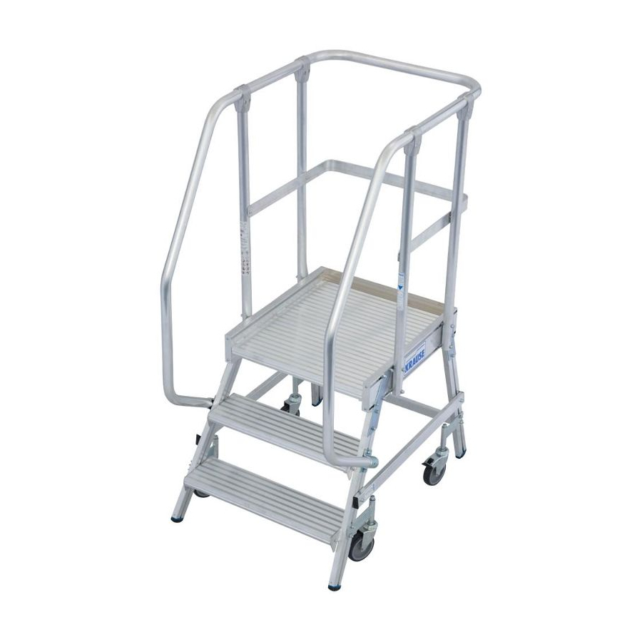
Single/Double-Sided Platform Ladder
GB
PL
Лестница с платформой с односторонним/ двухсторонним подъемом
RU
CZ
Assembly Instructions and User Manual
GB
Инструкция по монтажу и применению
RU
CZ
Version 2.0 © 2020 KRAUSE-Werk
www.krause-systems.com
Advertisement
Chapters
Table of Contents

Subscribe to Our Youtube Channel
Related Manuals for KRAUSE 820136


Summary of Contents for KRAUSE 820136
- Page 1 Aufbau- und Verwendungsanleitung Assembly Instructions and User Manual Instrukcja monta¿u i u¿ytkowania Инструкция по монтажу и применению Version 2.0 © 2020 KRAUSE-Werk PodestLeiter einseitig/beidseitig begehbar Single/Double-Sided Platform Ladder Лестница с платформой с односторонним/ двухсторонним подъемом www.krause-systems.com...
- Page 2 PodestLeiter einseitig/beidseitig begehbar Single/Double-Sided Platform Ladder Лестница с платформой с односторонним/двухсторонним подъемом...
-
Page 3: Table Of Contents
Inhaltsverzeichnis 1. Allgemeines .................. 4 1.1 Verantwortungsbereich des Betreibers ........4 1.2 Hersteller ................. 4 1.3 Prüfbescheinigung ..............4 1.4 Gewährleistung ................ 4 1.5 Urheber- und Schutzrechte ............. 5 1.6 Ausgabedatum ................ 5 2. Angaben zum Produkt ..............5 2.1 Bestimmungsgemäßer Gebrauch ..........5 2.2 Nicht bestimmungsgemäßer Gebrauch ........ -
Page 4: Allgemeines
1. Allgemeines Diese Anleitung beschreibt den Auf- und Abbau, sowie die Verwendung der KRAUSE PodestLeitern, einseitig oder beidseitig begehbar. In dieser Anleitung sind wichtige Sicherheitshinweise angegeben. Lesen Sie deshalb die Anleitung vor der Benutzung sorgfältig durch und machen Sie sich mit den Sicherheitsbestimmungen vertraut. -
Page 5: Urheber- Und Schutzrechte
10 Jahren ab Verkaufsdatum des betroffenen Teiles. Der Hersteller behält sich vor, das bemängelte Teil nach eigenem Ermessen auszutauschen oder zu reparieren. Für Gewähr- leistungsansprüche aus der Dokumentation ist die am Verkaufstag gültige Aufbau- und Verwendungsanleitung maßgebend. Ein Gewährleistungsanspruch ist ausgeschlossen, wenn Schäden aus einem oder mehreren der nachfolgenden Gründe entstanden sind: –... -
Page 6: Technische Daten
40,2 51,4 62,8 Ges.gew. inkl. Handläufe ca. kg 32,4 35,8 39,6 43,0 55,2 66,6 Art.-No. 820136 820143 820150 820167 820174 820181 Handlauf (beidseitig verwendbar) Stufenzahl Art.-No. 820426 820433 820440 Ersatzteile (Bitte achten Sie bei der Bestellung von Fahrrollen auf die gebremste/ungebremste Ausführung.) - Page 7 PodestLeiter, beidseitig begehbar Länge Breite Maximalbelastung: Geländer: 150 kg 40 mm Alu-Rohr, Höhe 1 m Stufentiefe: Handläufe: 175 mm 40 mm Alu-Rohr, als Zubehör erhältlich 125 mm Fahrrollen, zwei mit Bremse, Absenkend Podestmaß: Fahrrollen: 600 x 700 mm beim Besteigen Arbeitshöhe bis ca.
-
Page 8: Sicherheitsbestimmungen
3. Sicherheitsbestimmungen 3.1 Geltende Vorschriften Für den Auf- und Abbau, die Standsicherheit und die Verwendung der PodestLeiter gelten folgende Vorschriften und Handlungsanleitungen: DIN EN 131-2 Leitern; Anforderungen, Prüfung, Kennzeichnung DIN EN 131-7 Mobile Podestleitern DGUV Information 208-016 Handlungsanleitungen für den Umgang mit Leitern und Tritten 3.2 Sicherheitsbestimmungen für den Aufbau und die Nutzung –... - Page 9 – ausgesetzt sind, die PodestLeitern nicht einsetzen. Ebenso muss die Lagerung gegen sonstige Feuchtigkeits- und Temperatureinflüße, Säure- und Laugeneinwirkungen entstanden sind, ist die PodestLeiter für Ihre Benutzung zu sperren. – Die PodestLeiter ist ausschließlich im komplett montierten Zustand inkl. eventuell notwendigem Ballastierungsgewicht zu benutzen, die Einzelbauteile sind nicht als Steighilfen gedacht.
-
Page 10: Sicherheitsbestimmungen Beim Verfahren Der Podestleiter
3.3 Sicherheitsbestimmungen beim Verfahren der PodestLeiter – Beim Verfahren dürfen sich kein Material und keine Personen auf der PodestLeiter befinden. – Die PodestLeiter darf nur von Hand und nur auf fester, ebener, hindernisfreier Aufstellfläche verfahren werden. – Das Verfahren der PodestLeiter unter Zuhilfenahme von anderen Fahrzeugen jeglicher Art ist verboten. -
Page 11: Bezeichnung Der Einzelteile
HINWEIS ZUR NUTZUNG DER AUFBAUANLEITUNG Die Aufbauanleitung beschreibt die Montage der unterschiedlichen Aufbauvarianten der PodestLeiter. Lesen Sie vor dem Aufbau die komplette Montageanleitung und beachten Sie die Unterschiede der verschiedenen Aufbauvarianten. Je nach Plattformhöhe werden zur Erhöhung der Standfestigkeit Ballastgewichte benötigt. Diese sind bereits in den jeweiligen Verbindungsstreben integriert und dürfen nicht entfernt werden. -
Page 12: Montage Des Podestes
4.3 Montage des Podestes M 8 x 15 mm 8,4 mm 22 x 22 x 22 x 1 + 1 1 + 1... -
Page 14: Montage Des Stützteils/Steigteils
4.4 Montage des Stützteils/Steigteils Anzugsdrehmoment: 20 Nm... -
Page 15: Montage Der Verbindungsstreben
4.5 Montage der Verbindungsstreben M 8 x 32 mm 19 mm 8,4 mm ACHTUNG! PodestLeiter noch nicht begehen! Verschrauben Sie die beiden Verbindungsstreben fest an den markierten Positionen im Nutkanal mittels Schrauben, Hülsen, Unterlegscheiben und Muttern. -
Page 16: Montage Der Geländer Und Fahrrollen
4.6 Montage der Geländer und Fahrrollen... -
Page 17: Montage Der Knieleisten Und Des Geländers
4.7 Montage der Knieleisten und des Geländers M 8 x 52 mm 38 mm 8,4 mm M 6 x 25 mm 6,4 mm M 6 x 25 mm M 8 x 52 mm Die Hammerkopfschrauben mit Hülsen an den vier Geländerpfosten montieren. Diese Hammerkopfschrauben sind in den Nutkanal einzuführen. -
Page 18: Montage Des Handlaufs
4.8 Montage des Handlaufs M 8 x 15 mm 8,4 mm 8 mm... -
Page 19: Montage Der Fahrrollen
4.9 Montage der Fahrrollen M 8 x 20 mm 8,4 mm 8 mm 8 mm – Die PodestLeiter wird auf eine 8 mm starke Unterlage gestellt. Anschließend ist die entsprechend gekennzeichnete Fahrrolle fest anzuziehen. Achtung: Fahrrollen nicht – Es ist darauf zu achten, dass bei Montage der Rollen der Federkörper vertikal und horizontal ausgerichtet sein muss, um eine einwandfreie Funktion zu gewährleisten. -
Page 20: Checkliste Leiternprüfung
5. Checkliste Leiternprüfung gemäß DGUV Information 208-016 (BGI 694) - Page 25 Table of contents 1. General information ..............26 1.1 Owner‘s responsibilities ............26 1.2 Manufacturer ................. 26 ............. 26 ................26 1.5 Intellectual property rights ............. 27 1.6 Issue date ................27 2. Product information ..............27 2.1 Intended use ................27 2.2 Improper use .................
-
Page 26: General Information
1. General information This manual contains information on how to assemble, disassemble and use single and double-sided KRAUSE platform ladders, as well as important safety instructions. For this reason, please read this manual and the safety instructions in particular, carefully before assembling and using your platform ladder. -
Page 27: Intellectual Property Rights
defects of the affected component. The manufacturer reserves the right to replace or repair the defective component at his discretion. Any warranty claims arising from the documentation will be assessed on the basis of the Assembly Instructions and User Manual valid on the date of sale. The warranty does not apply to any damage caused by any or a combination of the following: –... -
Page 28: Technical Data
36,8 40,2 51,4 62,8 Total weight incl. grab rails approx. kg 32,4 35,8 39,6 43,0 55,2 66,6 Item No. 820136 820143 820150 820167 820174 820181 Handrail (suitable for right/left side) Number of steps Item No. 820426 820433 820440 Spare parts (please make sure to specify whether you want castors with/without brakes when ordering) - Page 29 Double-sided platform ladder Length Width Maximum load: Rails: 150 kg 40 mm aluminium pipe, 1 metre high Step depth: Grab rails: 175 mm 40 mm aluminium pipe, available as an accessory 125 mm castors, two with brakes, which lower when a Platform dimensions: Castors: 600 x 700 mm...
-
Page 30: Safety Instructions
3. Safety instructions 3.1 Applicable standards The platform ladder‘s assembly and disassembly, stability and use is governed by the following regulations and instruction manuals: DIN EN 131-2 Ladders; Requirements, testing, marking DIN EN 131-7 Mobile ladders with platform DGUV Information 208-016 Instructions on the proper handling of ladders and step stools 3.2 Safety instructions for assembly and use... - Page 31 – The platform ladder must only be used when fully assembled and together with any ballast weights it might require. The ladder‘s individual parts must not be used as climbing equipment. – Platform ladders set up next to or on traffic routes must be made highly visible and protected from being knocked over.
-
Page 32: Safety Instructions For Moving The Platform Ladder
3.3 Safety instructions for moving the platform ladder – The platform ladder must not be moved while there are any materials or persons on it. – The platform ladder must only be moved by hand and on a solid, level surface that is free from any obstacles. -
Page 33: Individual Part Names
INFORMATION ON USING THE ASSEMBLY INSTRUCTIONS The Assembly Instructions describe how to assemble the platform ladder in a number and take note of the differences between the different assembly options. Depending on more stable. The ballast weights are integrated into the relevant connecting struts and must not be removed. -
Page 34: Fitting The Platform
4.3 Fitting the platform M 8 x 15 mm 8,4 mm 22 x 22 x 22 x 1 + 1 1 + 1... -
Page 36: Fitting The Supporting Legs/Ladder Section
4.4 Fitting the supporting legs/ladder section Tightening torque: 20 Nm... -
Page 37: Fitting The Connecting Struts
4.5 Fitting the connecting struts M 8 x 32 mm 19 mm 8,4 mm CAUTION! Do not yet climb onto the platform ladder! Tightly bolt the two connecting struts to the positions marked in the groove using the supplied screws, sleeves, washers and nuts. -
Page 38: Fitting The Rails And Castors
4.6 Fitting the rails and castors... -
Page 39: Fitting The Knee Bars And Rail
4.7 Fitting the knee bars and rail M 8 x 52 mm 38 mm 8,4 mm M 6 x 25 mm 6,4 mm M 6 x 25 mm M 8 x 52 mm Insert the hammer head bolts with the sleeves into the four railing posts. These hammer head bolts must be inserted into the channel. -
Page 40: Fitting The Handrail
4.8 Fitting the handrail M 8 x 15 mm 8,4 mm 8 mm... -
Page 41: Fitting The Castors
4.9 Fitting the castors M 8 x 20 mm 8,4 mm 8 mm 8 mm – Place the platform ladder on top of a 8 mm thick pad. Next, tighten the screws of the for each leg – Make sure that the spring component is vertically and horizontally aligned when fitting the castors to make sure that they will be working properly. -
Page 42: Ladder Inspection Checklist
5. Ladder inspection checklist DGUV Information 208-016 (BGI 694) - Page 47 Spis tres ´ ci 1. Informacje ogólne ..............48 ........48 ................48 ......48 ................48 ............ 49 1.6 Data wydania ................. 49 ............49 ........ 49 ......49 ..............50 ........52 ..........52 ............52 ..54 ..........
-
Page 48: Informacje Ogólne
1. Informacje ogólne – – – – – 1.2 Producent +48 74 851 88 00 +48 74 851 88 44 1.4 Gwarancja... -
Page 49: Data Wydania
– – – – – 1.5 Prawa autorskie i ochronne 1.6 Data wydania... - Page 50 0,13 0,18 0,22 0,26 0,30 30,0 33,4 36,8 40,2 51,4 62,8 32,4 35,8 39,6 43,0 55,2 66,6 Nr kat. 820136 820143 820150 820167 820174 820181 820662 820679 820686 820631 820648 820655 i wyd³u¿onymi barierekami 820426 820433 Nr kat. 820440 820365...
- Page 51 40 mm Aluminiowa rura, wys, 1 m 175 mm 600 x 700 mm 2,71 2,95 3,19 3,43 3,66 3,90 0,71 0,95 1,19 1,43 1,66 1,90 2 x 3 2 x 4 2 x 5 2 x 6 2 x 7 2 x 8 0,77 x 1,35 0,84 x 1,62...
- Page 52 DIN EN 131-2 Drabiny; Wymagania, Kontrola, DIN EN 131-7 Mobilne drabiny – – – –...
- Page 53 – – – – – – – – – –...
-
Page 54: Budowa
– oraz osoby. – – zabronione. – – – – 4. Budowa 4.1 Ogólne informacje... - Page 55 1 x imbus SW 5 1 x imbus SW 4 Podest Listwa jezdne...
- Page 56 M 8 x 15 mm 8,4 mm 22 x 22 x 22 x 1 + 1 1 + 1...
- Page 58 Moment dokrêcania...
- Page 59 M 8 x 32 mm 19 mm 8,4 mm...
- Page 61 4.7 Monta¿ listwy kolanowej i barierki M 8 x 52 mm 38 mm 8,4 mm M 6 x 25 mm 6,4 mm M 6 x 25 mm M 8 x 52 mm...
- Page 62 M 8 x 15 mm 8,4 mm 8 mm...
- Page 63 M 8 x 20 mm 8,4 mm 8 mm 8 mm – – –...
-
Page 64: Lista Kontrolna
5. Lista kontrolna... - Page 69 СОДЕРЖАНИЕ 1. Общие положения ..............70 1.1 Ответственность пользователя .......... 70 1.2 Производитель ..............70 1.3 Свидетельство о проверке ..........70 1.4 Г арантийные обязательства ..........70 1.5 Авторские права производителя ........71 1.6 Дата издания ................ 71 2. Данные о продукции ............... 71 2.1 Целевое...
-
Page 70: Общие Положения
1. Общие положения Эта инструкция описывает монтаж и демонтаж лестниц с платформой KRAUSE, односторонних и двусторонних, а также правила их применения. Вэтой инструкции указаны важные требования безопасности. В связи с этим прочтите внимательно эту инструкцию до начала монтажа и ознакомьтесь с требованиями безопасности. -
Page 71: Авторские Права Производителя
продажи и поставки поставщика. На дефекты материала гарантийные обязатель- ства действуют в течение 10-х лет со дня продажи. Производитель может по своему усмотрению поменять или отремонтировать повреждённую деталь. Для гарантий- ных обязательств, согласно документации, действует инструкция по монтажу и применению, действующая на день приобретения. Г арантийные права теряются при... -
Page 72: Технические Данные
36,8 40,2 51,4 62,8 Вес с поручнями кг 32,4 35,8 39,6 43,0 55,2 66,6 № арт. 820136 820143 820150 820167 820174 820181 Поручень (двухстороннее использование) Количество ступеней № арт. 820426 820433 820440 Запасные части (при заказе укажите наличие/отсутствие фиксатора) Ролик без... - Page 73 Лестница с платформой, двусторонняя Длина Ширина Макс. нагрузка: Поручень: 150 кг Алюм. труба 40 мм, высота 1 м Г лубина ступени: Перила: 175 мм Алюм. труба 40 мм, дополнительный аксессуар 125 мм, утапливаются при всхождении на лестницу, Размер платформы: Ролики: 600 x 700 мм...
-
Page 74: Требования Правил Безопасности
3. Требования безопасности 3.1 Действующие требования При монтаже, демонтаже и использовании лестницы с платформой действуют следующие предписания и положения: DIN EN 131-2 лестницы; требования, контроль, обозначения DIN EN 131-7 передвижные лестницы с платформой DGUV Information 208-016 руководство по работе с лестницами и подставками... - Page 75 должна обеспечиваться ее защита от вредных воздействий. При наличии повреждений лестницы, возникших вследствие воздействия на нее атмо- сферных явлений, влаги, температурных перепадов, контакта с кислотой или щелочью, ее использование недопустимо. – Лестница с платформой должна использоваться только в полностью соб- ранном...
-
Page 76: Требования Безопасности При Перемещении Лестницы
3.3 Требования безопасности при перемещении лестницы – При перемещении лестницы с платформой на ней не должны находиться люди или предметы. – Лестницу с платформой перемещать только вручную, по твёрдой и ровной поверхности. – Недопустимо перемещение лестницы при помощи любых транспортных средств. -
Page 77: Обозначения Составных Частей
ПРИМЕЧАНИЯ ПО ИСПОЛЬЗОВАНИЮ ИНСТРУКЦИИ ПО МОНТАЖУ Инструкция описывает порядок монтажа лестниц с платформой в различных вариантах исполнения. Перед монтажом прочтите всю инструкцию по монтажу и обратите внимание на отличия при монтаже различных вариантов. В зависимости от высоты площадки необходимо применение балластных грузов для... -
Page 78: Монтаж Платформы
4.3 Монтаж платформы M 8 x 15 мм 8,4 мм 22 x 22 x 22 x 1 + 1 1 + 1... -
Page 80: Монтаж Опорной/ Лестничной Части
4.4 Монтаж лестницы и опорной рамы Крутящий момент: 20 Nm... -
Page 81: Монтаж Соединительных Перекладин
4.5 Монтаж соединительных перекладин M 8 x 32 мм 19 мм 8,4 мм Внимание! На лестницу подниматься еще нельзя! Обе соединительные перекладины крепятся на маркированных местах боковин снаружи лестницы. -
Page 82: Монтаж Поручней И Роликов
4.6 Монтаж ограждения и роликов... -
Page 83: Монтаж Планки На Уровне Колен И Перил
4.7 Монтаж защитной планки и ограждений M 8 x 52 мм 38 мм 8,4 мм M 6 x 25 мм 6,4 мм M 6 x 25 мм M 8 x 52 мм Болты с втулками вставьте в опоры ограждения. Вставьте головку болта в канал. Затяните... -
Page 84: Монтаж Поручней
4.8 Монтаж поручней M 8 x 15 мм 8,4 мм 8 мм... -
Page 85: Монтаж Роликов
4.9 Монтаж роликов 8,4 мм 8 мм M 8 x 20 мм 8 mm – Установите лестницу с платформой на подставку толщиной 8 мм. Затем установите маркированный ролик и затяните соединения. Внимание: ролики должны устанавливаться строго в соответствии с маркировкой! –... -
Page 86: Контрольный Лист
5. Контрольный лист... - Page 91 Obsah ............... 92 ..........92 .................. 92 ................. 92 ..................92 ............. 93 ............93 ................. 93 ........... 93 ............ 93 ..............94 ..............96 ..............96 ....96 ..98 ............ 98 ..................98 ............98 ............99 ..............100 ..........
- Page 92 – – – – – Am Kreuzweg 3 D 36304 Alsfeld +49 (0) 6631 / 795-0 +49 (0) 6631 / 795-139 1.3 Certifikát 1.4 Záruka...
- Page 93 – – – – –...
- Page 94 0,22 0,26 0,30 30,0 33,4 36,8 40,2 51,4 62,8 32,4 35,8 39,6 43,0 55,2 66,6 820136 820143 820150 820167 820174 820181 820426 820433 820440 1 ks Ø 125 mm Ø125 mm Ø 125 mm Ø125 mm Ø 125 mm Ø125 mm Ø...
- Page 95 Länge Breite 175 mm 600 x 700 mm asi m 2,71 2,95 3,19 3,43 3,66 3,90 0,71 0,95 1,19 1,43 1,66 1,90 2 x 3 2 x 4 2 x 5 2 x 6 2 x 7 2 x 8 0,77 x 1,35 0,84 x 1,62 0,86 x 1,90...
- Page 96 DIN EN 131-2 DIN EN 131-7 DGUV Information 208-016 – – – – –...
- Page 97 – – – – – – – – – –...
- Page 98 – – – – – – –...
- Page 100 M 8 x 15 mm 8,4 mm 22 x 22 x 22 x 1 + 1 1 + 1...
- Page 102 20 Nm...
- Page 103 M 8 x 32 mm 19 mm 8,4 mm...
- Page 105 M 8 x 52 mm 38 mm 8,4 mm M 6 x 25 mm 6,4 mm M 6 x 25 mm M 8 x 52 mm...
- Page 106 M 8 x 15 mm 8,4 mm 8 mm...
- Page 107 M 8 x 20 mm 8,4 mm 8 mm 8 mm – – –...
- Page 112 KRAUSE-Werk GmbH & Co. KG Am Kreuzweg 3 D 36304 Alsfeld Telefon: +49 (0) 6631 / 795-0 Telefax: +49 (0) 6631 / 795-139 www.krause-systems.com...
Need help?
Do you have a question about the 820136 and is the answer not in the manual?
Questions and answers