Advertisement
Quick Links
Advertisement
Chapters

Related Manuals for Sony HDVF-C35W


Summary of Contents for Sony HDVF-C35W
- Page 1 HD ELECTRONIC VIEWFINDER HDVF-C35W 電気製品は、安全のための注意事項を守らないと、 火災や人身事故になることがあります。 このオペレーションマニュアルには、事故を防ぐための重要な注意事項と製品の取 り扱いかたを示してあります。このオペレーションマニュアルをよくお読みのう え、製品を安全にお使いください。お読みになったあとは、いつでも見られるとこ ろに必ず保管してください。 OPERATION MANUAL [Japanese/English] 1st Edition (Revised 2)
- Page 2 日本語 安全のために 電気製品は、安全のための注意事項を守らないと、火災や感電などにより死亡や 警告表示の意味 大けがなど人身事故につながることがあり、危険です。 事故を防ぐために次のことを必ずお守りください。 オペレーションマニュアルおよび 製品では、次のような表示をして 安全のための注意事項を守る います。表示の内容をよく理解し てから本文をお読みください。 3、4 ページの注意事項をよくお読みください。 定期点検をする 長期間安全に使用していただくために、定期点検を実施することをおすすめしま す。点検の内容や費用については、ソニーのサービス担当者または営業担当者に この表示の注意事項を守らないと、 ご相談ください。 火災や感電などにより死亡や大け がなど人身事故につながることが 故障したら使用を中止する あります。 ソニーのサービス担当者、または営業担当者にご連絡ください。 注意を促す記号 万一、異常が起きたら ・ 異常な音、におい、煙が出たら ・ 落下させたら a カメラの電源を切る。 b 接続ケーブルを抜く。 c ソニーのサービス担当者、または営業担当者に修理を依頼する。 行為を禁止する記号 炎が出たら a すぐにカメラの電源を切り、消火する。...
-
Page 3: Table Of Contents
目次 警告 ................3 概要 ..................4 使用上のご注意 ..............5 各部の名称と働き ............... 6 前面パネル/底面パネル ......... 7 LCD 画面のインジケーター........8 分解・改造しない カメラに取り付ける............9 視度と画面を調整する ............10 外装を外したり、改造したりすると、感 電の原因となります。 視度を調整するには ..........10 ビューファインダー内部の調整や設定お 画面を調整するには ..........11 よび点検を行う必要がある場合は、必ず アイピース部を取りはずす ..........12 サービストレーニングを受けた技術者に VF 筒部を取りはずす............13 ご依頼ください。... - Page 4 グレースケール表示 概要 画面左右に 10 ステップのグレースケールを表示できます。 このグレースケールを基準にして微細なアイリス調整を行 うことができます。 HD エレクトロニックビューファインダー HDVF-C35W MONO 表示 は、ソニーハイビジョンカラーカメラ用の 3.5 型カラー ビューファインダーです。 スイッチ操作により、カラー画像を白黒画像に切り換える ことができます。 本機には以下のような特長があります。 プリセット調整値への切り換え マルチスキャン あらかじめ調整しておいた明るさ、コントラスト、ピーキ カメラからの制御信号により、60i の他に 24PsF や 50i など ング、クロマレベルの設定を、アサイナブルスイッチ操作 の各種フォーマットに対応します。 によって切り換えることができます。 マーカー表示 アサイナブルスイッチ カメラ側でセンターマーカーやセーフティーゾーンマー プリセット調整値の切り換えや、機能を任意に割り当てる カーなどの表示が ON に設定されている場合、本機のス ことができるアサイナブルスイッチを 2 つ搭載しています。...
-
Page 5: 使用上のご注意
使用上のご注意 • 低温でのご使用時には、動解像度と輝度が低下いたしま す。 • 画面の表面からほこりを取り除くときは、ブロアーをお 使いください。 • 画面をクリーニングするときは、シンナーなどの溶剤は いっさい使用しないでください。 液晶画面の輝点・滅点について 本機の液晶パネルは有効画素 99.99% 以上の非常に精密度の 高い技術で作られていますが、画面上に黒い点が現れたり (画素欠け) 、常時点灯している輝点(赤、青、緑など)や 滅点がある場合があります。また、液晶パネルの特性上、 長期間ご使用の間に画素欠けが生じることもあります。こ れらの現象は故障ではありませんので、ご了承の上本機を お使いください。なお、これらの点が記録されることはあ りません。 使用上のご注意... -
Page 6: 各部の名称と働き
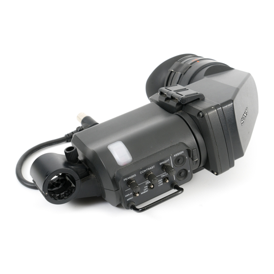
各部の名称と働き 1 コネクター 2 スライドストッパー 3 タリーランプ(後面) 4 アイカップ 5 視度調整リング VF 筒部 6 タリーランプ(前面) 前面パネル (7 ページ) ビューファインダーケーブル 底面パネル (7 ページ) a コネクター e 視度調整リング カメラの VF 端子に接続します。 画像が最もはっきり見えるように、このリングを回して視 度を調整します。 b スライドストッパー f タリーランプ(前面) 本機をカメラに取り付けて左右にスライドさせるとき、本 機がカメラからはずれるのを防ぎます。 カメラにタリー信号が入力されると点灯します。前面パネ ルの TALLY スイッチ (7 ページ)で明るさを調整できま c タリーランプ(後面) す。使わないときは、TALLY スイッチを OFF にしておき カメラにタリー信号が入力されると点灯します。... -
Page 7: 前面パネル/底面パネル
前面パネル/底面パネル 1 PEAKING つまみ 2CONTRAST つまみ 3BRIGHT つまみ 4 ASSIGN 1 スイッチ 前面パネル q; ASPECT/DISPLAY スイッチ 5 ASSIGN 2 スイッチ 9 ZEBRA スイッチ 6 TALLY スイッチ 底面パネル 8 MENU スイッチ 7 ENTER スイッチ a PEAKING(ピーキング調節)つまみ 初期設定では、白黒表示機能が割り当てられています。 画像の輪郭を補正します。カメラの映像出力には影響しま e ASSIGN(アサイナブル)2 スイッチ せん。右に回すと補正量が多くなります。 主に以下の 2 つの働きをします。 PRESET メニュー (18 ページ)の「PRESET」が「OFF」 • よく使う機能やプリセット調整値を任意で割り当てるこ に設定されているときのみ有効です。 とができます。... -
Page 8: Lcd 画面のインジケーター
LOW:タリーランプが暗くなる。 1 グリーンタリーインジケーター g ENTER(確定)スイッチ 2 TALLY/REC 選択したメニュー項目を確定します。 インジケーター ◆ メニュー操作について詳しくは、「メニューを使う」 (15 ペー 3 BATT ジ)をご覧ください。 インジケーター h MENU(メニュー表示)スイッチ メニューを表示します。 画像 ◆ メニュー操作について詳しくは、「メニューを使う」 (15 ペー ジ)をご覧ください。 4 SAVE i ZEBRA(ゼブラパターン)スイッチ インジケーター ゼブラパターンの表示をコントロールします。 ON:ゼブラパターンを表示する。 5 予備 インジケーター OFF:ゼブラパターンを表示しない。 MOMENT:ゼブラパターンが約 5 秒間表示されて消える。 6 MAG インジケーター j ASPECT/DISPLAY(表示比率/マーカー表示)ス インジケーター 7 ... -
Page 9: カメラに取り付ける
f MAG(拡大表示)インジケーター カメラに取り付ける ASSIGN 2 スイッチ(初期設定時)またはメニュー操作 (15 ページ)によって拡大表示機能を割り当てた ASSIGN 1 スイッチを押して画像を拡大表示したときに点灯します。 g (注意)インジケーター ご注意 カメラがある特定の状態になったとき点灯します。どの状 ビューファインダーを取り付けたあと、接眼レンズを太陽 態で点灯させるかは、カメラで設定できます。 に向けて放置しないでください。太陽光が接眼レンズを通 してビューファインダー内部に焦点を結び、火災の原因と ◆ インジケーターが点灯する条件を設定 / 確認する方法につ なることがあります。 いては、使用しているカメラのマニュアルをご覧ください。 溝 スライドガイド スライドストッパー 左右位置 固定リング コネクター VF 端子 カメラの左右位置固定リングをゆるめる。 本機裏側の溝をカメラ前面のスライドガイドにはめる。 本機を矢印の方向にスライドさせる。 本機を左右にスライドして取り付け位置を決め、カメ ラの左右位置固定リングを締める。 コネクターをカメラの VF 端子に差し込む。 カメラに取り付ける... -
Page 10: 視度と画面を調整する
ご注意 視度と画面を調整する カメラの VF 端子にコネクターがしっかり差し込まれてい ることを必ず確認してください。 取りはずすときは 視度を調整するには 取り付け操作の手順を逆に実行します。本機をカメラから 視度調整リングを回して、映像が最もはっきり見えるよう 抜き取るときは、スライドストッパーを引き上げてくださ に調整します。 い。 キャリングケースに収納するときのご注意 視度調整リング 本機をカメラに取り付けた状態でキャリングケースに収納 する場合は、本機とカメラが無理なくケースに収まるよう にしてください。本機やカメラに無理な力が加わると故障 や破損の原因になります。 視度範囲を遠視側にシフトするには 下記の手順で、色温度変換フィルターに市販のクローズ アップレンズをはめ込みます。 アイカップホルダーからアイカップをはずす。 「アイピース部を分解するには」 (14 ページ)の要領 で、色温度変換フィルターをはずす。 色温度変換フィルターから保護リングをはずす。 色温度変換フィルターのねじ溝にクローズアップレン ズをねじ込み(1) 、クローズアップレンズのねじ溝に 保護リングをねじ込む(2) 。 色温度変換 クローズアップ 保護リング フィルター レンズ クローズアップレンズと保護リングを取り付けた色温 度変換フィルターをアイカップホルダーにねじ込む。 視度と画面を調整する... -
Page 11: 画面を調整するには
◆ メニュー操作について詳しくは、 「メニューを使う」 (15 ページ)をご覧ください。 つまみの誤動作を避けるには MENU スイッチを 3 秒以上押すと、 「VR LOCK」と表示さ れ、 PEAKING、BRIGHT、CONTRAST の各つまみがロッ アイカップ 色温度変換フィルター クされて誤動作を防ぐことができます。もう一度 MENU ホルダー (クローズアップレンズと スイッチを 3 秒以上押すと、 「VR UNLOCK」と表示され、 保護リング取り付け済み) ロックが解除されます。 電源投入後は必ずロックが解除されます。 アイカップをはめる。 プリセット調整値を表示するには メニューを表示していない状態で ENTER スイッチを押し 画面を調整するには ます。 PRESET メニュー (18 ページ)の「PRST BRIGHT」 、 ご注意 「PRST CONTRAST」 、 「PRST PEAKING」の各項目で設 定された値が、LCD 画面の下部に約... -
Page 12: アイピース部を取りはずす
アイピース部を取りはず す 本機から目を離して撮影するような場合は、アイピース部 を取りはずすと画面全体が見やすくなります。アイピース 部をクリーニングするときも取りはずします。 この面を傷つけないように充分注意してください。 ◆ クリーニングについて詳しくは、 「画面や内部(LCD 画面や本 体のミラー)をクリーニングする」 (14 ページ)をご覧くださ い。 アイピース部を取り付けるには ロックリングを反時計方向いっぱいに回して、ロック ロックリングの合いマークと、VF 筒部の合いマークを リングの合いマークと VF 筒部の合いマーク ( いずれも 合わせる。 赤い線 ) を合わせる。 アイピース部先端の合いマークをロックリングの合い マークに合わせて、アイピース部を VF 筒部に差し込 ロックリング む。 パチンとはまるまで差し込んでください。 ロックリングを時計方向いっぱいに回し、ロックリン グの「LOCK」表示の矢印を、VF 筒部の合いマークに 合わせる。 ロックリングの合いマーク ご注意 VF 筒部の合いマーク 付属の(本機に組み込まれている)接眼レンズ以外のレン... -
Page 13: Vf 筒部を取りはずす
VF 筒部を取りはずす VF 筒部を取りはずして LCD 部を撮影者側に向けると、 LCD 画面を直接見ることができます。LCD 画面や本体内 部のミラーをクリーニングするときも VF 筒部を取りはず します。 ◆ LCD 画面や本体内部のミラーのクリーニング方法について詳し くは、14 ページをご覧ください。 リリースレバーを押しながら VF 筒部を引き上げる。 VF 筒部を取り付けるには VF 筒部 LCD 上部の爪 2 か所に VF 筒部の軸を引っ掛ける。 リリースレバー LCD 上部の爪 2 か所から VF 筒部の軸をはずす。 リリースレバーがカチッと音を立てて固定されるまで、 VF 筒部を押し下げる。 ご注意 VF 筒部の軸が LCD 上部の爪に確実に入っている状態 で... -
Page 14: 画像を拡大表示する
画像を拡大表示する 画面や内部(LCD 画面や 本体のミラー)をクリー ニングする 画像を縦横 2.25 倍に拡大表示して、フォーカス調整を容易 にすることができます。 画像を拡大表示するには、初期設定状態の ASSIGN 2 ス イッチまたはメニュー操作 (15 ページ)によって拡大表示 本機の画面や内部(LCD 画面や本体のミラー)をクリーニ 機能を割り当てた ASSIGN 1 スイッチを押します。押すた ングするときは、本機をカメラから取りはずし、内部の部 びに通常表示と拡大表示が切り換わります。 品を傷つけないように充分注意して行ってください。 拡大表示部分を選択するには ◆ 本機をカメラから取りはずす方法については、 「カメラに取り付 ける」 (9 ページ)の手順を参考にしてください。 拡大表示する部分は、画面の左上、右上、右下、左下、中 央(出荷時設定)のいずれかを選択することができます。 ◆ VF 筒部を取りはずす方法については、13 ページをご覧くださ い。 画面やミラーの表面からほこりを取り除くときは 右上 左上 ブロアーをお使いください。 中央... -
Page 15: メニューを使う
アイカップホルダーからアイカップをはずす。 メニューを使う アイカップホルダー内から、色温度変換フィルターを 保護リングごと回してはずす。 本機では、メニューを使って操作全般の設定を行います。 特殊環境での使用後のアフターケアについて 海辺やほこりの多い場所、温泉地などで使用した後は、以 下のようにクリーニングや確認を行ってください。 メニューモードの基本操作 • セットの中に入っている砂やほこりをエアーブラシ等で 慎重に取り除く。 メニューモードに入る。 • 海水中の塩分や温泉中の硫黄分が外装の非塗装面に付着 した場合は、アルコール等で速やかにクリーニングする。 MENU スイッチを押す。 ( 塩分や硫黄分が付着したままにしておくと、その部分が 白く腐食することがあります。) メニュー画面が表示されます。 • コネクターの接続面をクリーニングする。 • 上記のクリーニングを行った後に、一般動作チェックを 行い、正常に動作することを確認する。 ビューファインダーの画面上にカメラからの映像やメ ニューが表示されている状態でも、本機のメニューを表 示することができます。このとき、カメラからの映像 やメニュー表示は暗くなり、本機のメニューの後ろに 薄く表示されます。 メニューページを選ぶ。 1 ページ番号の前に?マークが表示されている状態 (ページ選択モード)で、ASSIGN 1 または ASSIGN 2 スイッチを押す。 ページが移動します。... - Page 16 • ページを選びなおすときは、MENU スイッチを押す 設定値を変更する。 と、ページ選択モードに戻ります。 設定値に ? マークが表示されている状態(設定値変更 • 設定項目に●マークが、設定値に ? マークがある場合 モード)で、ENTER スイッチを押して、設定値を変 (設定値変更モード)は、MENU スイッチを押すと 更する。 項目選択モードに戻ります。もう一度 MENU スイッ チを押すと、ページ選択モードになります。 設定値が数字の場合、ASSIGN 1 スイッチを押すと数 値が大きくなり、 ASSIGN 2 スイッチを押すと数値が小 項目を選ぶ。 さくなります。 1 選択したページの設定項目に マークが表示されて スイッチを押したままにすると数値が速く変化します。 いる状態(項目選択モード)で、ASSIGN 1 または ASSIGN 2 スイッチを押して、 マークを移動す 設定値を確定する。 る。 ENTER スイッチを押す。 ASSIGN 1 スイッチを押すと...
-
Page 17: メニュー一覧
メニュー一覧 • 選択できない項目は、設定値に「−−−」と表示されま ご注意 す。 • 項目によっては、前のメニュー項目で「ON」が選択され ていないと選択できないものがあります。 ページ メニュー 項目 設定値([ ] はお買い上 機能 げ時の設定) FUNCTION ASSIGN. 1 KNEE/PRST/[MONO]/ ASSIGN 1 スイッチに機能を割り当てます。 MAG/GRAY KNEE:KNEE 補正回路の ON/OFF の切り換え PRST:PRESET の ON/OFF を切り換えます。スイッチを 1 秒 以上押したままにすると、PRESET メニューの「PRESET SEL 1」と「PRESET SEL 2」にて設定されたプリセット 調整値が切り換わります。 MONO:白黒表示の ON/OFF の切り換え MAG:拡大表示の ON/OFF を切り換えます。スイッチを 1 秒 以上押したままにすると、拡大表示する部分が切り換わり... - Page 18 ページ メニュー 項目 設定値([ ] はお買い上 機能 げ時の設定) INDICATOR DIM2 IND MODE [NOR]/REV LCD 画面のインジケーターの点灯ポジションと光量を切り換えま す。 NOR :VF 筒部をはずしたときのインジケーターの光量を設定し ます。 REV :VF 筒部を取り付けたときのインジケーターの光量を設定 します。 NON STANDARD 1 〜 [50] 〜 100 インジ ケーターの光量を調整します。 1 〜 [50] 〜 100 MAG インジケーターの光量を調整します。 EXTEND 1 〜 [50] 〜 100 予備インジケーターの光量を調整します。...
- Page 19 ページ メニュー 項目 設定値([ ] はお買い上 機能 げ時の設定) STATUS DISPLAY ASSIGN. 1 OFF/[ON] ASSIGN 1 スイッチに割り当てられている機能の状態変化を表示す るか(ON)表示しないか(OFF)を選択します。 ASSIGN. 2 OFF/[ON] ASSIGN 2 スイッチに割り当てられている機能の状態変化を表示す るか(ON)表示しないか(OFF)を選択します。 BRIGHT OFF/[ON] 前面パネルの BRIGHT つまみの設定を表示するか(ON)表示しな いか(OFF)を選択します。 CONTRAST OFF/[ON] 前面パネルの CONTRAST つまみの設定を表示するか(ON)表示 しないか(OFF)を選択します。 PEAKING OFF/[ON] 前面パネルの PEAKING つまみの設定を表示するか(ON)表示し ないか(OFF)を選択します。 DISPLAY MODE PANEL REV [AUTO]/MAN LCD 画面を上下左右に反転する方法を設定します。...
- Page 20 グリーンタリー/ TALLY/REC / 仕様 BATT / / MAG /予備/ SAVE 入力信号 一般 Pb、Pr 0.7 Vp-p、同期なし、75 Ω 終端 電源 DC10.5 〜 17.0 V(カメラから供給) 1.0 Vp-p、同期あり、75 Ω 終端 消費電力 6.3 W 使用温度 0゜C 〜+ 45゜C 接続端子 保存温度 − 20゜C 〜+ 60゜C カメラ端子丸型 20 ピン 質量 850 g 外形寸法(単位:mm) 付属品 オペレーションマニュアル(1)...
- Page 21 English - Reorient or relocate the receiving antenna. WARNING - Increase the separation between the equipment and receiver. - Connect the equipment into an outlet on a circuit To reduce the risk of fire or electric shock, different from that to which the receiver is connected. do not expose this apparatus to rain or - Consult the dealer or an experienced radio/TV moisture.
- Page 22 Bereich, z.B. Fernsehstudio). Overview ...........23 Notes ............24 For the customers in Europe The manufacturer of this product is Sony Corporation, 1- Location and Function of Parts ....25 7-1 Konan, Minato-ku, Tokyo, Japan. Front Panel/Bottom Panel......26 The Authorized Representative for EMC and product Indicators on the LCD Screen....
-
Page 23: Overview
A 10-step grayscale can be displayed at the left and right of the screen to provide a standard for fine iris adjustments. The HDVF-C35W HD Electronic Viewfinder is a 3.5-inch Monochrome display color viewfinder for use with a Sony high-definition color A color or monochrome display can be selected by a camera. -
Page 24: Notes
Notes • The LCD panel fitted to this unit is manufactured with high precision technology, giving a functioning pixel ratio of at least 99.99%. Thus a very small proportion of pixels may be “stuck”, either always off (black), always on (red, green, or blue), or flashing. In addition, over a long period of use, because of the physical characteristics of the liquid crystal display, such “stuck”... -
Page 25: Location And Function Of Parts
This indicator can be covered when not in use. d Eyecup Blocks external light while you are shooting. Over time the eyecup may become cracked. If this occurs, it should be exchanged. Sony part number: 3-209-288-01 Location and Function of Parts... -
Page 26: Front Panel/Bottom Panel
Front Panel/Bottom Panel 1 PEAKING control 2 CONTRAST control 3 BRIGHT control 4 ASSIGN 1 switch Front panel 0 ASPECT/DISPLAY switch 5 ASSIGN 2 switch 9 ZEBRA switch 6 TALLY switch Bottom panel 8 MENU switch 7 ENTER switch a PEAKING control •... -
Page 27: Indicators On The Lcd Screen
f TALLY switch Controls the TALLY indicator (page 25) located on the 1 Green tally indicator front of the viewfinder. 2 TALLY/REC HIGH: The tally indicator brightness is set to high. indicator OFF: The tally indicator is disabled. LOW: The tally indicator brightness is set to low. 3 BATT indicator g ENTER switch... -
Page 28: Attaching The Viewfinder To The Camera
switch with which the magnification function is assigned Attaching the Viewfinder by menu operation (page 35). to the Camera (attention) indicator This indicator lights when the camera detects certain conditions. The particular conditions which cause the indicator to light up can be set by the camera. Note For information on how to set up and verify the conditions When the viewfinder is attached, do not leave the camera... -
Page 29: Adjusting Focus And Screen
Position the viewfinder by sliding it from side to side, Adjusting Focus and and tighten the left-right positioning ring on the camera. Screen Connect the plug to the VF connector on the camera. Note Adjusting the Focus Always check to be sure that the plug is firmly inserted into the camera’s VF connector. -
Page 30: Adjusting The Screen
Replace the color conversion filter into the eyecup To increase the contrast: Turn the control holder. clockwise. Set “CHROMA” in the FUNCTION menu (page 36) to adjust the chroma level. To prevent accidental operation of the controls To prevent accidental operation of the PEAKING, CONTRAST, and BRIGHT controls, lock them by pushing down the MENU switch for 3 seconds or more so Eyecup holder... -
Page 31: Detaching The Eyepiece
Detaching the Eyepiece Detaching the eyepiece gives you a clear view of the screen even with your eye away from the viewfinder. Also, detach the eyepiece to clean it. For details on cleaning, see “Cleaning the Screen or Interior” on page 34. Do not scratch this surface. -
Page 32: Detaching The Viewfinder Barrel
Detaching the Viewfinder Barrel By detaching the viewfinder barrel and turning the LCD screen towards the shooter, the LCD screen can be viewed directly. The barrel must be detached to clean the viewfinder’s LCD screen and internal mirror. For details on cleaning the LCD screen and internal mirror, see “Cleaning the Screen or Interior”... -
Page 33: Magnifying The Picture
seconds after the ASSIGN 1 or ASSIGN 2 switch is Magnifying the Picture pushed. To facilitate focus adjustments, you can magnify the picture by 2.25 times vertically and horizontally. To magnify the picture, push the ASSIGN 1 switch (at its factory-setting) or the ASSIGN switch with which the magnifying function is assigned by the menu operation (page 35). -
Page 34: Cleaning The Screen Or Interior
Remove the color conversion filter, together with the Cleaning the Screen or protection ring, from inside the eyecup holder. Check the viewfinder after using it in harsh Interior environments Check the following points after using the viewfinder in a harsh environment such as a beach, a dusty area, or a hot To clean the screen or internal mirror of the viewfinder, spring resort. -
Page 35: Using The Menu
setting mode), push the MENU switch to return to Using the Menu item select mode. Push the MENU switch again to return to page select mode. Select menu items. Many of the viewfinder’s functions can be set by a menu operation. -
Page 36: List Of Menu Items
Enter the setting. Repeat steps 2 to 5 to set other menu items. Push the ENTER switch. End menu operations. The setting is entered and the menu returns to item Push the MENU switch repeatedly until the menu select mode. page disappears from the display. - Page 37 Page Menu item Settings Description (default in [NOR] INDICATOR DIM IND MODE Adjusts the brightness and sets the lighting positions of /REV the indicators on the LCD screen. NOR: Adjusts the brightness of indicators when the viewfinder barrel is detached. REV: Adjusts the brightness of indicators when the viewfinder barrel is attached.
- Page 38 Page Menu item Settings Description (default in [OFF] PRESET PRESET Selects the setting made by the PEAKING, CONTRAST, and BRIGHT controls on the front of the viewfinder and the chroma level setting in the FUNCTION menu or by “PRST BRIGHT,” “PRST CONTRAST,” “PRST PEAKING,” and “PRST CHROMA”...
-
Page 39: Specifications
Effective Format Horizontal Vertical Specifications scanning scanning scanning lines frequency frequency (kHz) (Hz) General 1080 23.98PsF 26.97 47.95 24PsF Power supply 10.5 to 17.0 V DC (supplied by the camera) 25PsF 28.13 Power consumption 29.97PsF 33.72 59.94 6.3 W 30PsF 33.75 Operating temperature 28.13... - Page 40 Note Always verify that the unit is operating properly before use. SONY WILL NOT BE LIABLE FOR DAMAGES OF ANY KIND INCLUDING, BUT NOT LIMITED TO, COMPENSATION OR REIMBURSEMENT ON ACCOUNT OF THE LOSS OF PRESENT OR PROSPECTIVE PROFITS DUE TO FAILURE OF...
- Page 41 保守等) と異なる目的で本マニュアルを使用することを禁止 します。 The material contained in this manual consists of information that is the property of Sony Corporation and is intended solely for use by the purchasers of the equipment described in this manual. Sony Corporation expressly prohibits the duplication of any...
- Page 42 Sony Corporation Printed in Belgium 2011.12 08 HDVF-C35W (SY) © 2007 3-209-373-03(2)
Need help?
Do you have a question about the HDVF-C35W and is the answer not in the manual?
Questions and answers