Table of Contents
Advertisement
Quick Links
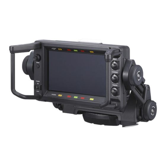
HD ELECTRONIC VIEWFINDER
HDVF-EL70
HDVF-EL75
OUTDOOR HOOD
VFH-790
Conditions of Use:
(1) Please use this information only for the purpose of repair and recycling of Sony products. Using this information for any purpose other
than the purpose described foregoing is forbidden.
(2) Do not copy, replicate, reproduce, alter, translate, transmit, sell, lease, or distribute this information in whole or in part without the prior
written permission of the author.
Revision of Information:
This information may be changed or updated at any time without any prior notice. Please confirm that this information is up-to-date before
using it.
SERVICE MANUAL
1st Edition
Serial No. 120001 and Higher
Advertisement
Table of Contents

Related Manuals for Sony HDVF-EL70


Summary of Contents for Sony HDVF-EL70
- Page 1 VFH-790 Conditions of Use: (1) Please use this information only for the purpose of repair and recycling of Sony products. Using this information for any purpose other than the purpose described foregoing is forbidden. (2) Do not copy, replicate, reproduce, alter, translate, transmit, sell, lease, or distribute this information in whole or in part without the prior written permission of the author.
- Page 2 Ce manual est destiné uniquement aux personnes compétentes en charge de l’entretien. Afin de réduire les risques de décharge électrique, d’incendie ou de blessure n’effectuer que les réparations indiquées dans le mode d’emploi à moins d’être qualifié pour en effectuer d’autres. Pour toute réparation faire appel à une personne compétente uniquement. HDVF-EL70/HDVF-EL75...
-
Page 3: Table Of Contents
Color Temperature Adjustment ........4-3 1-7. Replacing the OLED Panel ........... 1-13 1-8. Replacing VF Holder Unit Components ....... 1-16 1-8-1. Harness (VF Connection 1) (HDVF-EL70)..1-16 5. Spare Parts 1-8-2. Harness (VF Connection 2) (HDVF-EL75)..1-22 1-8-3. Arm (L) Sub Assembly ........1-23 5-1. -
Page 5: Service Overview
SW-1732 PR-337 LE-417 VR-366 SW-1731 1-2. Connector Input/Output Signals 1-2-1. Conforming Cable When connecting the HDVF-EL75 to a camera at the time of installation or service, use the supplied VF cable. Sony part No.: 1-838-608-11 VF side CAMERA side HDVF-EL70/HDVF-EL75... -
Page 6: External Connectors
ON: +5 V ON: +5 V R TALLY R TALLY OFF: GND OFF: GND No connection No connection UNREG GND GND for UNREG UNREG GND GND for UNREG +10.5 V to 17 V +10.5 V to 17 V UNREG UNREG HDVF-EL70/HDVF-EL75... - Page 7 HDVF-EL70 D-SUB (25P, MALE) (External view) Signal Specifications 1.0 Vp-p, Zi = 75 Z Y VIDEO (X) Pr VIDEO GND GND for Pr VIDEO 0.7 Vp-p, Zi = 75 Z Pr VIDEO (X) Pb VIDEO GND GND for Pb VIDEO 0.7 Vp-p, Zi = 75 Z...
-
Page 8: Onboard Switches
Depending on model OFF: HDVF-EL75 HDVF-EL70 IND SEL 2 Selection of function of upper-right indicator Depending on model OFF: BATT IND (HDVF-EL75) SECRET IND (HDVF-EL70) 3 to 6 Not used All OFF VERSION UP OFF: Normal Not used *1: These bits are set to OFF when the board was purchased. Change the setting according to the model that contains this board. -
Page 9: Circuit Description
The circuit consisting of an FET (Q1402) immediately after UNREG_IN, a transistor (Q1401), and peripheral parts prevents inrush current, reverse connection, backflow, and transient burst. Inrush current is reduced by gradually activating the gate by the current flowing through the Q1402 body diode. HDVF-EL70/HDVF-EL75... - Page 10 CPU outputs a fan stop signal through IC1452 to deactivate IC1801. To observe the predetermined startup sequence, each power voltage becomes active in the specified sequence using the EN pin of each IC and load switches IC452, IC1502, and IC1602. HDVF-EL70/HDVF-EL75...
-
Page 11: Removing/Installing Boards
Hexagon socket head bolts 2. Remove the three screws. 3. Remove the LE-415 board from the connec- tor on the PR-337 board. LE-415 board Connector (PR-337 board) 4. Install the removed parts by reversing the steps of removal. HDVF-EL70/HDVF-EL75... - Page 12 ICs on the new PR-337 board. IC204 Radiation sheets Harnesses 5. Make settings of the DIP switch (S1201) on HDVF-EL70 HDVF-EL75 the new PR-337 board. (Refer to Section 1-3.) 6. Install the removed parts by reversing the steps of removal. S1201...
-
Page 13: Sw-1730 Board
7. Remove the drip-proof rubber and the cush- ion (PWR SW) from the power switch on the SW-1730 board. Cusion (PWR SW) Drip-proof rubber CN4 CN3 SW-1730 board 8. Install the removed parts by reversing the steps of removal. HDVF-EL70/HDVF-EL75... -
Page 14: Board
3. Remove the three volume knobs. Volume knobs 4. Disconnect the harness from the connector on the VR-366 board. 5. Remove the three screws and remove the VR-366 board. VR-366 board Harness 6. Install the removed parts by reversing the steps of removal. 1-10 HDVF-EL70/HDVF-EL75... -
Page 15: Sw-1731 Board/Sw-1732 Board
SW-1732 board Harness Harness SW-1731 board 4. Install the removed parts by reversing the steps of removal. 1-5-6. LE-416 Board/LE-417 Board 1. Remove the two screws and detach the front mask while releasing the two claws. Front mask Claws 1-11 HDVF-EL70/HDVF-EL75... -
Page 16: Replacing The Dc Fan
3 of removal. Fan cover Attach the fan cover carefully so that the fan harness is not caught by the fan cover and check that the fan harness passes through the notch of the chassis. DC fan Fan harness Notch 1-12 HDVF-EL70/HDVF-EL75... -
Page 17: Replacing The Oled Panel
1. Remove the PR-337 board. (Refer to Section 1-5-2.) 2. Remove the two screws to detach the panel guard (lower). Panel guard (lower) 3. Remove the two screws and remove the display unit from the rear cover. Rear cover Display unit 1-13 HDVF-EL70/HDVF-EL75... - Page 18 6. Remove the tape (13X50). Nylon rivet When sticking tape (13X50), clamp the two harnesses as shown in the figure. Tape (13X50) Harnesses Tape (13X50) Harnesses Min. 10 mm Min. 10 mm Tape (13X50) IC100 IC4212 Harness prohibited area 1-14 HDVF-EL70/HDVF-EL75...
- Page 19 11. Remove the two screws to detach the panel B2 x 6 bracket (left). OLED panel 12. Disconnect the three harnesses from the connectors. B2 x 6 Harnesses Panel bracket (right) 13. Install a new OLED panel by reversing the steps of removal. 1-15 HDVF-EL70/HDVF-EL75...
-
Page 20: Replacing Vf Holder Unit Components
M3 : M2.6 : 0.4 ? 0.10 N.m 0.2 ? 0.03 N.m M2 : 1-8-1. Harness (VF Connection 1) (HDVF-EL70) Removal 1. Remove the PR-337 board. (Refer to Section 1-5-2.) 2. Perform steps 1 to 3 in “Replacing the OLED Panel”... -
Page 21: Harness (Vf Connection 2) (Hdvf-El75)
(VF Connection 1). assembly 16. Pull the harness (VF Connection 1) out of the harness hole in the arm (L) sub assembly. groove Radiation sheet Harness Locking wire (VF connection 1) saddle Ground wire (Harness (VF connection 1)) 1-17 HDVF-EL70/HDVF-EL75... - Page 22 P2.6 Slide lock spacer 19. Set the knob (STOP/FREE) to “FREE.” 20. Turn the slide lock screw counterclockwise to Knob a position where screw threads of about 3 mm (STOP/FREE) are visible. Slide lock screw About 3 mm 1-18 HDVF-EL70/HDVF-EL75...
- Page 23 25. Remove the two hexagon socket head bolts and remove the VF connector from the VF Hexagon socket head bolts CN holder. VF CN holder VF connector When assembling, install the VF CN holder first, VF connector, and then nut plate. Nut plate (50P) 1-19 HDVF-EL70/HDVF-EL75...
- Page 24 28. Remove the screw to detach the cable retainer Hole (VF). 29. Pull the harness (VF Connection 1) out of the hole in the slide base. Harness clamp Cable retainer (VF) B3 x 5 Harness (VF connector 1) 1-20 HDVF-EL70/HDVF-EL75...
- Page 25 . When installing the VF connector, pay attention to the installation order. (Refer to step 25 of removal.) . When sticking the radiation sheet, pay attention to the arrangement of the harness. (Refer to step 13 of removal.) 1-21 HDVF-EL70/HDVF-EL75...
- Page 26 8. Pull the harness (VF CONNECTION 2) out of the hole in the VF holder. K2 x 4 B3 x 5 K2 x 4 VF CN plate 20P CN cover 9. Install the removed parts by reversing the steps of removal. 1-22 HDVF-EL70/HDVF-EL75...
-
Page 27: Arm (L) Sub Assembly
(screen) may tilt. . To make the right and left arms parallel, it is recommended that you put the rear cover vertically on a level object (such as desk) and tighten setscrews to place the arms on the horizontal surface. 1-23 HDVF-EL70/HDVF-EL75... -
Page 28: Arm (R) Sub Assembly
4. Remove the two screws (B3 x 5) to detach the lift base cover (R). 5. Detach the lift arm cover (R). Tilt lock shoe assembly K3 x 6 B3 x 5 Lift arm cover (R) Lift base cover (R) 1-24 HDVF-EL70/HDVF-EL75... - Page 29 (screen) may tilt. . To make the right and left arms parallel, it is recommended that you put the rear cover vertically on a level object (such as desk) and tighten setscrews to place the arms on the horizontal surface. 1-25 HDVF-EL70/HDVF-EL75...
-
Page 30: Adjusting The Arm Lift Angle
1-8-5. Adjusting the Arm Lift Angle The arm lift angle is set as shown in the figure. Check and adjust the lift angle as needed. Lift angle range of the arm HDVF-EL70 HDVF-EL75 Lift stopper Lift stopper Lift stopper Lift stopper... -
Page 31: Notes On Replacing Parts
Gear engaging portion Lift center shaft groove Both ends of spring Both ends of spring Slide base (P) Lift center Warm gear shaft groove shafts U grooves (upper/lower) Gear engaging portion Pan shaft side surface Lift center shaft 1-27 HDVF-EL70/HDVF-EL75... -
Page 32: Tilt Lock Shoe
1-9-2. Tilt Lock Shoe The tilt stopper pin position of the tilt lock shoe of the HDVF-EL70 is different from that of the HDVF-EL75. Attach the tilt stopper pin at the correct position referring to the figure below. -
Page 33: Checking Friction In The Panning Direction (Hdvf-El75)
When the friction is lower than the typical value, increase the number of pan shaft spacers. When the friction is higher than the typical value, decrease the number of pan shaft spacers. Up to five pan shaft spacers are installable. 1-29 HDVF-EL70/HDVF-EL75... -
Page 34: List Of Tool, Required Equipment, And Adjustment Equipment
Screw tightening Required Equipment Equipment Model name HD camera The HD camera described in related products in the operation manual. A general-purpose personal computer Adjustment Equipment Adjuster Model name Display color analyzer Konica Minolta sensing CA-310 or the equivalent 1-30 HDVF-EL70/HDVF-EL75... -
Page 35: Firmware And Pld Upgrading
When you need to upgrade the software data, contact your local Sony Sales Office/Service Center. 1-11-3. Writing and Rewriting PLD Internal Data When you need to upgrade the PLD internal data, contact your local Sony Sales Office/Service Center. 1-31 HDVF-EL70/HDVF-EL75... -
Page 36: Replacing Fuses
. The ordinary soldering iron can be used but the iron tip has to be applied to the solder joint for a slightly longer time. The printed pattern (copper foil) may peel away if the heated tip is applied for too long, so be careful. 1-32 HDVF-EL70/HDVF-EL75... -
Page 37: Diagnostics
2-2. Device Check This unit has a self-diagnosis function that checks the communication function of each device. The result of diagnosis is displayed in “S08 DIAGNOSIS” of a SERVICE menu. (For more details, refer to Section 3-4.) HDVF-EL70/HDVF-EL75... -
Page 38: Internal Test Signal
To change the signal type to be output to the test pin (TP501/PR-337 board), change the settings of bit1 and bit2 of S601 (PR-337 board). Output signals S601 on the PR-337 board settings Bit 1 Bit 2 ― (Not output) Y or G Pb or B Pr or R HDVF-EL70/HDVF-EL75... - Page 39 To change the signal point to be output to the test pin (TP501/PR-337 board), change the settings of bit3 to bit5 of S601 (PR-337 board). Output signals S601 on the PR-337 board settings Bit 3 Bit 4 Bit 5 ― ([1]) ― ([4]) ― ([5]) HDVF-EL70/HDVF-EL75...
-
Page 41: Setting Menu
The MENU switch is used when canceling the contents of setting in progress and returning to the page selection mode or TOP menu. BRIGHT control CONTRAST control PEAKING control This control setting is required when entering a TOP menu. BRIGHT control MENU control CONTRAST control MENU switch PEAKING control HDVF-EL70/HDVF-EL75... - Page 42 Press the MENU control for two seconds or more with the “?” mark displayed in the setting value to be returned to the factory setting (in the setting value change mode). *: The operation above is applied to only the operation from a TOP menu. Refer to “3-2. TOP Menu”. HDVF-EL70/HDVF-EL75...
-
Page 43: Top Menu
The items required for maintenance of this unit such as the electrical adjustment, hours meter, or self-diagnosis function of this unit are summarized. 3-3. OPERATION Menu The setting items required for operation of this unit are summarized in this OPERATION menu. For more details, refer to the Operation Manual supplied for this unit. HDVF-EL70/HDVF-EL75... -
Page 44: Service Menu
*3: While the SERVICE menu is displayed, this item is disabled (menu display is not erased automatically). *4: This item is available only for HDVF-EL70 and only when S800-2 on the PR-326 board is set to ON. (Refer to Section 1-3.) *5: Necessarily operates in the OFF state when the power is turned on. - Page 45 The upper part is emphasized in contour. RIGHT: The right is emphasized in contour. LOWER: The lower part is emphasized in contour. LEFT: The left is emphasized in contour. (Continued) *5: Necessarily operates in the OFF state when the power is turned on. HDVF-EL70/HDVF-EL75...
- Page 46 *7: The current display is shifted to the execution screen below when moving a “→” mark to EXEC and pressing the MENU control. This function is executed when moving the “→” mark to “YES” and pressing the MENU control. HDVF-EL70/HDVF-EL75...
- Page 47 NG: A problem exists in chromaticity correction. POWER Only display Displays the self-diagnosis result of power supply to the panel module. OK: Normal NG: A problem exists in power supply. Only display Displays the fan self-diagnosis result. Normal Failure ——: Undefined (Continued) HDVF-EL70/HDVF-EL75...
- Page 48 S11 RESET MENU RESET EXEC *8: The items on page S03 in the SERVICE menu is adjusted during factory setting. They are not reset even if MENU RESET is executed. For the adjustment, refer to “Section 4 Electrical Alignment”. HDVF-EL70/HDVF-EL75...
-
Page 49: Electrical Alignment
MONOCHROME → OFF CHROMA → 0 MATRIX → ITU709 6 MENU: OPERATION PAGE: 03 PEAKING ITEM: PEAKING MODE → STD 7 MENU: OPERATION PAGE: 04 MAGNIFICATION ITEM: MAGNIFICATION → OFF 8 MENU: OPERATION PAGE: 05 PRESET ITEM: PRESET → OFF HDVF-EL70/HDVF-EL75... -
Page 50: Required Equipment
. Display color analyzer: Konica Minolta sensing CA-310 or the equivalent Related equipment . Color camera: HDC4800/4300 HD color camera: HDC2100/2000 HDC2600/2500/2400/1700 series HSC300R/HSC100R series HDCU2000/2500/1700 . Optical fiber cable 4-1-3. Connection HDVF-EL70 Optical Fiber cable CRANE TRACKER CONTROL NETWORK TRUNK SDI 1 SDI 2 SDI MONI TEST OUT... -
Page 51: Color Temperature Adjustment
= 0.313 ?0.005 Specifications: y = 0.329 ?0.005 4. Repeat steps 2 and 3 so that each specification is satisfied. 5. Set ADJUST ITEM to OFF. Setting MENU: SERVICE PAGE: S03 COLOR TEMP ITEM: ADJUST ITEM → OFF HDVF-EL70/HDVF-EL75... -
Page 53: Spare Parts
Therefore, specified parts should be used in the case of replacement. 2. Standardization of Parts Some repair parts supplied by Sony differ from those used for the unit. These are because of parts common- ality and improvement. 3. Stock of Parts Parts marked with “o”... -
Page 54: Exploded Views
4-558-935-01 s COVER (C), REAR 4-195-862-02 s PAD, REAR 4-195-869-03 s ADHESIVE(TALLY) 4-195-870-02 s COVER, TALLY 4-262-515-02 s SHEET (FERRITE CORE) 4-196-297-02 s SHEET(D),RADIATION 7-682-548-04 s SCREW +B 3X8 7-682-903-19 s SCREW +PWH 3X6 7-683-407-04 s BOLT,HEXAGON SOCKET 3X14 HDVF-EL70/HDVF-EL75... - Page 55 4-150-565-01 s SCREW +B 3X5 NI (SCOTCH GRIP) 4-558-936-01 s FRAME (B), REAR 4-195-861-01 s GUARD(LOWER),PANEL 4-198-669-01 s SUPPORT (L=9) 4-262-514-01 s SHEET (FAN), SEALING 3-278-255-01 s TAPE (BT) 4-736-184-01 s SHEET, HARNESS GUARD 7-682-548-09 s SCREW +B 3X8 HDVF-EL70/HDVF-EL75...
- Page 56 4-195-865-01 s GUIDE,LIGHT 4-150-565-01 s SCREW +B 3X5 NI (SCOTCH GRIP) 4-488-383-01 s TAPE (13X50) //C 4-196-225-01 s SHEET (UPPER) S, TALLY (EL70) (for HDVF-EL70) 4-195-839-01 s SHEET (UPPER) P, TALLY (EL75) 7-621-772-38 s SCREW +B (for HDVF-EL75) 7-682-548-04 s SCREW +B 3X8...
- Page 57 4-150-565-01 s SCREW +B 3X5 NI (SCOTCH GRIP) 4-183-519-01 s KNOB(B),RE 4-558-933-01 s BEZEL 4-195-859-04 s KNOB, VOLUME 4-195-863-01 s COVER (LEFT), HANDLE 4-558-248-01 s BASE (LEFT), HANDLE 4-195-867-01 s COVER (RIGHT), HANDLE 4-558-249-01 s BASE (RIGHT), HANDLE 4-196-282-01 s SHEET(HANDLE),SEALING 7-683-403-04 s BOLT,HEXAGON SOCKET 3X6 HDVF-EL70/HDVF-EL75...
- Page 58 VF Holder Unit (S) (HDVF-EL70) : Regulated parts Refer to “HOLDER ASSY” P2.6 HEXAGON SOCKET BOLT Part No. SP Description 1-482-025-11 s BEAD, FERRITE (CASE) 1-967-456-14 s HARNESS, SUB (VF CONNECTION1) 3-604-479-02 s ALOCK +B4X8 3-675-929-02 s NUT (50P), PLATE...
- Page 59 7-682-561-04 s SCREW +B 4X8 4-195-519-01 s BASE GUARD (P) 7-683-435-04 s BOLT,HEXAGON SOCKET 5X10 4-558-243-01 s BASE (TOP), PAN 4-558-244-01 s BASE (BOTTOM), PAN 4-558-246-01 s SHEET, PAN 4-197-161-01 s HOLDER, CABLE 4-577-013-01 s SPACER, PAN SHAFT 3-746-631-01 s BAND, BINDING HDVF-EL70/HDVF-EL75...
- Page 60 Holder Assembly HDVF-EL70 P2.6 Refer to “VF HOLDER SUB ASSY (S)” HDVF-EL75 Part No. SP Description 3-172-801-01 s SPRING (PIA.20) 3-701-506-01 s SET SCREW, DOUBLE POINT 3X4 3-719-381-02 s SCREW (M2X4) 4-558-232-01 s KNOB (ARM SIDE) 4-558-927-01 s STOPPER KNOB SCREW...
- Page 61 VF Holder Sub Assembly (S) (HDVF-EL70) P2.6 P2.6 Part No. SP Description Part No. SP Description A-2066-482-B s VF HOLDER SUB ASSY (S) 4-558-932-01 s COVER, REAR X-2590-749-1 s ARM(R) SUB ASSY 4-558-226-01 s TILT BASE COVER (R) X-2590-751-1 s ARM(LS) SUB ASSY...
- Page 62 4-558-228-01 s LIFT BASE COVER (R) 4-558-229-01 s NAME PLATE (LIFT LOCK) 4-558-230-01 s LIFT ARM COVER (R) 4-558-231-01 s NAME PLATE (TILT LOCK) 4-146-663-01 s SCREW +K 3X6 (SCOTCH GRIP) 4-477-967-01 s SCREW, +B M3X5 7-682-146-09 s SCREW +P 3X5 5-10 HDVF-EL70/HDVF-EL75...
-
Page 63: Supplied Accessories
5-3. Supplied Accessories --------- HDVF-EL70 --------- Ref. No. or Q'ty Part No. SP Description A-1793-995-B s HOOD ASSY, INDOOR X-2025-305-2 s CLOTH ASSY, CLEANING 3-992-267-01 s PLATE,NUMBER 4-258-596-02 s OPERATION MANUAL --------- HDVF-EL75 --------- Ref. No. or Q'ty Part No. -
Page 65: Diagrams
TEMP SENSOR D SUB (25P,MALE) I2C2 I2C4 I2C1 IC1303 I2C HUB IC1202 X1201 VOLT DETECT IC1302 16MHz IC1301 EEPROM CAM_EEPROM_EN IC1201 TALLY_SYNC_EN PDWN S1201 FAN_ALARM PANEL_READY PANEL_RECONFIG UP_TALLY_DIMMER IC106 POWER_OFF_CTL VR-366 SW-1730 LE-415 LE-417 LE-416 SW-1731 SW-1732 Overall (1/2) HDVF-EL70/HDVF-EL75... - Page 66 DC/DC CONV. TPS5420 R1173H001 IC1704 +1.8V A S-1333A18 IC1703 -5.0V A -5.0V A Charge Pump Analog I/F MAX1697 F1801 IC1801 FAN ON DC/DC CONV. TPS5420 CN11 FAN H IC1452 FAN P ALARM TCON +8.5V ON I/O EXPANDER I2C2 Overall (2/2) HDVF-EL70/HDVF-EL75...
-
Page 67: Frame Wiring
Frame Wiring Frame Wiring PR-337 LE-415 HDVF-EL70 Y VIDEO(X) Y_VIDEO(X) Pr VIDEO(G) Y_VIDEO(G) Pr VIDEO(X) Pb_VIDEO(X) UNREG 7-10 7-10 UNREG UNREG D1-16 Pb VIDEO(G) Pb_VIDEO(G) 11-14 11-14 Pb VIDEO(X) Pr_VIDEO(X) UP_TALLY_OUT UP_TALLY_OUT DRIVE PEAKING CTL Pr_VIDEO(G) DIMMER DIMMER UP TALLY... -
Page 69: Revision History
Revision History Date History Contents 2021. 1 1st Edition 9-932-773-01 HDVF-EL70/HDVF-EL75... - Page 72 HDVF-EL70 (SY) Printed in Japan Sony Corporation HDVF-EL75 (SY) E 2021. 1 08 9-932-773-01 ©2021...
Need help?
Do you have a question about the HDVF-EL70 and is the answer not in the manual?
Questions and answers