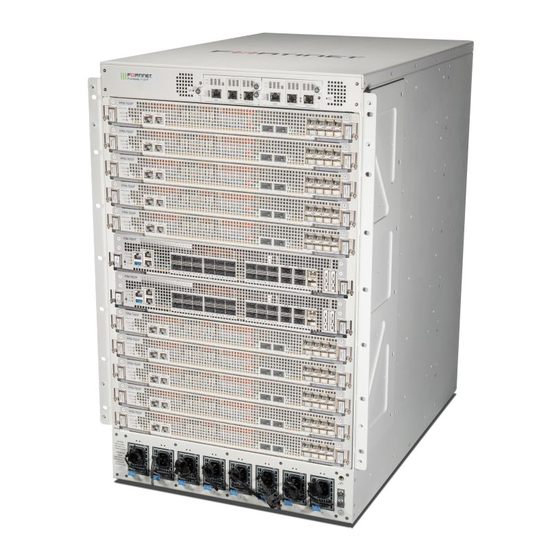
Summary of Contents for Fortinet FortiGate-7000F Series
Page 1
FortiGate-7121F System Guide FortiGate-7000F Series...
Page 2
FORTINET DOCUMENT LIBRARY https://docs.fortinet.com FORTINET VIDEO GUIDE https://video.fortinet.com FORTINET BLOG https://blog.fortinet.com CUSTOMER SERVICE & SUPPORT https://support.fortinet.com FORTINET TRAINING & CERTIFICATION PROGRAM https://www.fortinet.com/support-and-training/training.html NSE INSTITUTE https://training.fortinet.com FORTIGUARD CENTER https://fortiguard.com/ END USER LICENSE AGREEMENT https://www.fortinet.com/doc/legal/EULA.pdf FEEDBACK Email: techdoc@fortinet.com April 8, 2021 FortiGate-7121F System Guide...
FortiGate-7000F hardware assembly and rack mounting Installing optional accessories Front mounting brackets Cable bracket kit Front air filter kit Power cord clamps Mounting the FortiGate-7000F chassis in a four-post rack Mounting the FortiGate-7000F chassis in a two-post rack Inserting FIMs and FPMs Getting started with FortiGate-7000F Configuring the SLBC management interface Confirming startup status Multi VDOM mode Changing data interface network settings Resetting to factory defaults Restarting the FortiGate-7000F Managing individual FortiGate-7000F FIMs and FPMs Special management port numbers HA mode special management port numbers Managing individual FIMs and FPMs from the CLI Connecting to individual FIM and FPM CLIs of the secondary FortiGate-7000F in an FortiGate-7121F System Guide Fortinet Technologies Inc.
Page 4
Fortinet Technologies Inc. HA configuration Firmware upgrades Firmware upgrade basics Verifying that a firmware upgrade is successful Upgrading the firmware running on individual FIMs or FPMs Upgrading FIM firmware Upgrading FPM firmware Installing FIM firmware from the BIOS after a reboot Installing FPM firmware from the BIOS after a reboot Synchronizing FIMs and FPMs after upgrading the primary FIM firmware from the BIOS 43 FortiGate-7000F System Management Module System Management Module failure System Management Module LEDs About SMM alarm levels Using the console ports Connecting to the FortiOS CLI of the FIM in slot 1 Connecting to the FortiOS CLI of the FIM in slot 2 Connecting to the SMC SDI CLI of the FPM in slot 3 Changing the SMM admin account password FortiGate-7000F chassis slots IPMB addresses Rebooting an FIM or FPM from the SMC SDI CLI Comlog System event log (SEL) Sensor data record (SDR) Common SMM CLI operations Cautions and warnings Environmental specifications Safety Regulatory notices Federal Communication Commission (FCC) – USA...
Change log Fortinet Technologies Inc. Change log Date Change description April 8, 2021 Removed information about the FPM-7620F console port, which is not supported. March 30, 2021 Initial release. FortiGate-7121F System Guide...
FortiGate-7000F chassis The FortiGate-7121F is a 16U 19-inch rackmount 12-slot chassis with a 1Tbps fabric backplane and 50Gbps base backplane designed by Fortinet. The fabric backplane provides network data communication a mong chassis slots and the base backplane provides management and synchronization communication among the chassis slots. FortiGate-7000F front panel The FortiGate-7000F chassis is managed by two redundant System Management Modules (SMMs 1 and 2). Each SMM includes an ethernet connection as well as two switchable console ports that provide console connections to the modules in the chassis slots. Chassis modules include two Fortinet Interface Modules (FIMs) in slots 1 and 2 and up to ten Fortinet Processor Modules (FPMs) in slots 3 to 12. The active SMM controls chassis cooling and power management and provides an interface for managing the FIMs and FPMs in the chassis. Do not operate the FortiGate-7000F chassis with open slots on the front or back panel. For optimum cooling performance and safety, each chassis front panel slot must contain an FIM or FPM or an FIM or FPM blank panel (also called a dummy card). In addition, all cooling fan trays, power supplies or power supply slot covers must be installed while the chassis is operating. The FPM blank panels shipped with the chassis package should be kept available in case an FIM or FPM is removed from the chassis. If an FIM or FPM fails and you don't have a replacement FIM or FPM or an available blank panel, you should keep the failed FIM or FPM in the chassis slot until you receive a replacement. Power is provided to the chassis using eight h ot swappable 200-240 VAC, 50-60 Hz 2000W AC power supply units (PSUs). FortiGate-7121F System Guide Fortinet Technologies Inc.
Page 7
FortiGate-7000F chassis Fortinet Technologies Inc. FortiGate-7000F front panel, (showing AC PSUs, example module configuration) SMM 1 SMM 2 FPM-7620F (FPM slots 3, 5, 7, 9, 11) FIM-7921F (FIM slots 1 and 2) FPM-7620F (FPM slots 4, 6, 8, 10, 12)
FortiGate-7000F chassis Fortinet Technologies Inc. FIM-7921F interface module The FIM-7921F interface module is a hot swappable module that provides data, management, and session sync/heartbeat interfaces, base b ackplane switching, hardware acceleration, and fabric backplane session-aware load balancing for a FortiGate-7000F series chassis. The FIM-7921F includes an integrated switch fabric, five NP7 processors to load balance millions of data sessions over the FortiGate-7000F 400Gbps fabric backplane channel to FPM processor modules. The FIM-7921F also includes a 50Gbps base backplane channel for base backplane management communication with each FPM in the chassis, one 1Tbps fabric backplane channel for fabric backplane communication with the other FIM in the chassis, and a second 50Gbps base backplane channel for base backplane communication with the other FIM in the chassis. The FIM-7921F also includes two 4 TByte SSD log disks in a RAID-1 configuration. The SSDs are accessible from the FIM-7921F front panel but should not be removed. The FIM-7921F can be installed in any FortiGate-7000F series chassis in chassis hub/switch slots 1 or 2. The FIM- 7921F includes eighteen front panel 100GigE QSFP28 fabric channel data network interfaces (1 to 18) and two 400GigE QSFP-DD fabric channel data network interfaces (19 and 20). Interfaces 1 to 18 can be connected to 100Gbps data networks. Interfaces 19 and 20 can be connected to 400Gbps data networks. Y ou can also change the interface type of interfaces 19 and 20 and change the speeds of all of the data interfaces. The FIM-7921F also includes two 100 GigE QSFP28 base channel management interfaces (M1 and M2) and two 25 GigE SPF28 base channel management interfaces (M3 and M4). The management interfaces can be used for HA heartbeat communication and session synchronization between two chassis in HA mode or for other management functions such as remote logging. Y ou can also change the speeds of the management interfaces. The FIM-7921F includes a console port to provide console access to the FIM-7921F CLI. FIM-7921F front panel 19 and 20 Status, alarm...
FortiGate-7000F chassis Fortinet Technologies Inc. chassis fabric backplane and two 50Gbps management connections to the FIMs over base backplane. FPM-7620Fs are installed in chassis slots 3 and up. The FPM-7620F also includes two front panel 100GigE QSFP28 fabric channel data interfaces (1 and 2) and eight 10/25GigE SFP28 fabric channel data interfaces (3 to 10). Interfaces 1 and 2 can be connected to 100Gbps data networks. Interfaces 3 to 10 can be connected to 25Gbps data networks. FPM data network interfaces increase the number of data interfaces supported by FortiGate-7000F. Data traffic received by these interfaces is sent over the fabric backplane to the FIM NP7 processors to be load balanced back to the FPMs. The FPM-7620F processes sessions using a dual CPU configuration, accelerates network traffic processing with two NP7 processors and accelerates content processing with eight CP9 processors. The NP7 network processors are connected by the FIM switch fabric so all supported traffic types can be fast path accelerated by the NP7 processors. FPM-7620F front panel 3 to 10 Status, Alarm, MGMT 25/10GigE fabric channel and Power LEDS 10/100/1000BASE-T SFP28 data network Power Power copper management Power interfaces...
FortiGate-7000F chassis Fortinet Technologies Inc. FortiGate-7000F back panel Fan Tray 3 Fan Tray 2 Fan Tray 1 Chassis Ground Connector Fan Tray 6 Fan Tray 5 Fan Tray 4 Registering your FortiGate-7000F FortiGate-7000F series products are registered according to the chassis serial number. You need to register your chassis to receive Fortinet customer services such as product updates and customer support. You must also register your product for FortiGuard services. Register your product by visiting https://support.fortinet.com. To register, enter your contact information and the serial numbers of the Fortinet products that you or your organization have purchased. FortiGate-7121F System Guide...
FortiGate-7000F chassis Fortinet Technologies Inc. FortiGate-7121F chassis schematic The FortiGate-7121F chassis schematic shows the communication channels between chassis components including the SMMs (MGMT1 and MGMT2), the FIMs (FIM1 and FIM2), and the FPMs (FPM3 to FPM12). MGMT1 (inactive by default, IPMB 0x22) MGMT2 (active by default, IPMB 0x20) IPMB SMC SDI SMC SDI SERIAL 1G to FIMs FPM11 IPMB 0x96 2x400G 2x50G to FIMs Data SMC SDI...
FortiGate-7000F chassis Fortinet Technologies Inc. passive refers to the SMM that is controlling the chassis. The MGMT interfaces and console ports on both SMMs are always available. Each FIM and FPM and the S MMs have a Shelf Management Controller (SMC). These SMCs support I PMB communication between the active SMM and the FIMs and FPMs and other chassis components for s toring and sharing sensor data that the SMM uses to control chassis cooling and power distribution. The FortiGate-7000F also includes serial communications to allow console access from the SMM to all FIMs and FPMs. The base backplane includes 1Gbps ethernet management connections between the SMMs and the FIMs. T he base backplane also supports 50Gbps Ethernet communication for management and heartbeat communication between FIMs and FPMs. FIM1 and FIM2 (IPMB addresses 0x82 and 0x84) are the FIM interface modules in slots 1 and 2. FIM data interfaces connect the chassis to data networks. NP7 processors in the FIMs use session-aware load balancing (SLBC) to distribute data sessions over the FIM Integrated Switch Fabric (ISF) to the 10x400Gbps connections over the fabric backplane to the FPMs. Data communication between FIM1 and FIM2 occurs over a 1TB fabric connection. The FIM 1Gbps MGMT1 and MGNT2 interfaces are used for Ethernet management access to chassis components. The 2x100Gbps M1 and M2 interfaces are used for HA heartbeat communication between chassis. The 2x25Gbps M3 and M4 interfaces are used for remote logging or other management functions. FPM3 to FPM12 (IPMB addresses 0x86 to 0x98) are the FPM processor modules in slots 3 to 12. These worker modules process sessions distributed to them over the fabric backplane by the NP7 processors in the FIMs. FPMs include NP7 processors to offload sessions from the FPM CPU and CP9 processors that accelerate content processing. FPMs also include data interfaces that increase the number of data interfaces supported by the FortiGate-7000F. Data sessions received by the FPM data interfaces are sent over the fabric backplane to the F IM NP7 processors t o be load balanced back to the FPMs using SLBC. Chassis hardware information This section introduces FortiGate-7000F hardware components and accessories including power requirements and ...
FortiGate-7000F chassis Fortinet Technologies Inc. Eight power cord management clamps. One set of 4-post rack mounting components. One set of 2-post rack mounting components. One pair of cable management side brackets. Two front mounting brackets. Twenty-four M4x6 flat-head screws. Six M4x8 large head pan-head screws. Six rubber feet. Two USB to RJ-45 RS-232 console cables. One RJ-45 Ethernet cable. Optional accessories and replacement parts The following optional accessories can be ordered separately: Description FG-7121F-FAN FortiGate-7121F fan tray. FG-7121F-PS-2KAC 2000W AC power supply units (PSUs) for the FortiGate-7121F. FG--7121F-CH FortiGate-7121F chassis including 2x SMM, 6x fan trays, and 8x ACPSUs. Additional FIMs and FPMs.
FortiGate-7000F chassis Fortinet Technologies Inc. Supplied Power Supply Units (PSUs) Power supplied by each PSU 2000W Max Power Consumption 9754W Average Power Consumption 8296W Max Current 8 x 10A Heat Dissipation 35114KJ/h (33261BTU/h) Cooling fans, cooling air flow, and minimum clearance The FortiGate-7000F chassis contains six hot swappable cooling fan trays installed in the back of the chassis. Each fan tray includes two fans that operate together. When the fan tray LED is green, both fans are operating normally. If the LED ...
FortiGate-7000F chassis Fortinet Technologies Inc. Cooling Fan Tray Retention Retention Screw Screw Outlet Grill Outlet Grill Retention Retention Screw Screw Cooling air flow and required minimum air flow clearance When installing the chassis, make sure there is enough clearance for effective cooling air flow. The following diagram shows the cooling air flow through the chassis and the locations of fan trays. Make sure the cooling air intake and warm air exhaust openings are not blocked by cables or rack construction because this could result in cooling performance reduction and possible overheating and component damage. FortiGate-7121F System Guide...
FortiGate-7000F chassis Fortinet Technologies Inc. FortiGate-7000F cooling air flow and minimum air flow clearance FortiGate-7121F chassis (side View) Front Back 100 mm 100 mm Trays Cool air Warm Air Intake Exhaust Trays 675 mm Cool air enters the chassis through the chassis front panel and warm air exhausts out the back. For optimal cooling, allow 100 mm of clearance at the front and back of the chassis. Optional air filter You can purchase an optional NEBS compliant air filter kit that includes a front filter that fits over the front of the chassis. ...
FortiGate-7000F chassis Fortinet Technologies Inc. AC PSUs and supplying AC power to the chassis The FortiGate-7000F chassis front panel can include up to eight hot swappable 200-240V, 10A AC PSUs. The capacity of each PSU is 1800W (90% of full capacity of 2000W). See FortiGate-7000F back panel on page 9 for locations of the PSUs. The number of PSUs required by a chassis depends on the number of FIMs and FPMs in the chassis. For example, a FortiGate-7000F chassis containing two FIMs and six FPMs requires four PSUs to provide a total of 7200W. A chassis containing two FIMs and ten FPMs requires six PSUs to provide a total of 10800W. You can add extra PSUs to provide redundancy. See Power consumption for different FortiGate-7000F configurations on page 17. If the chassis does not have enough power because PSUs have failed or become disconnected, the a ctive SMM will begin shutting down FPMs starting at the highest slot number. All PSUs should be connected to AC power. To improve redundancy you can connect each PSU to a separate power source. Use a C15 Power cable, supplied with the chassis, to connect power to each PSU C16 power connector. C15/C16 power connectors are used for high temperature environments and are rated up to 120°C. AC PSU showing C16 power connector Latch Power Connector The PSU LED indicates whether the PSU is operating correctly and connected to power. If this LED is not lit, check to make sure the PSU is connected to power. If the power connection is good then the PSU has failed and should be ...
FortiGate-7000F chassis Fortinet Technologies Inc. Module Max power Number of Total max power (W) consumption (W) modules FIM-7921F 1194 FPM-7620F 716 ...
FortiGate-7000F chassis Fortinet Technologies Inc. You can hot swap a PSU without powering down the FortiGate-7000F as long as four PSUs are connected to power and operating normally. If you need to hot swap one of four operating PSUs, you should do this during a quiet period, because if the FortiGate-7000F is operating with less that four PSUs, some of the FPMs may be shut down. 1. Attach an ESD wrist strap to your wrist and to an ESD socket or to a bare metal surface on the chassis or frame. 2. Turn off the power being supplied to the power supply and disconnect the power cord. 3. Press the latch towards the handle until the PSU is detached then pull it out of the chassis. 4. Insert a replacement PSU into the chassis and slide it in until it locks into place. 5. Connect the PSU power terminals as described above. 6. Turn on power to the PSU. 7. Verify that the PSU status LED is solid green meaning that the PSU is powered up and operating normally. Connecting the FortiGate-7000F chassis to ground The FortiGate-7000F chassis includes a ground terminal on the rear the bottom of the FortiGate-7000F back panel. The ground terminal provides two connectors to be used with a double-holed lug such as Thomas & Betts PN 54850BE. This connector must be connected to a local ground connection. You need the following equipment to connect the FortiGate-7000F chassis to ground: An electrostatic discharge (ESD) preventive wrist strap with connection cord. One green 6 AWG stranded wire with listed closed loop double-hole lug s uitable for minimum 6 AWG copper wire, such as Thomas & Betts PN 54850BE.
FortiGate-7000F chassis Fortinet Technologies Inc. Turning on FortiGate-7000F chassis power Connect AC power to PSUs 1 to 8. Once the FortiGate-7000F chassis is connected to power the chassis powers up. If the chassis is operating correctly, the LEDs on the PSUs and fans should be lit. As well, the LEDs on the S MMs should be lit. When the chassis first starts up you should also hear the cooling fans operating. In addition, if any modules have been installed in the chassis they should power on and their front panel LEDs should indicate that they are starting up and operating normally. FortiGate-7121F System Guide...
FortiGate-7000F hardware assembly and rack mounting The FortiGate-7000F chassis must be mounted in a standard 19-inch rack and requires 16U of vertical space in the rack. This chapter describes how to attach accessories to the FortiGate-7000F chassis, how to install the chassis in a 4-post or 2-post rack, and how to install FIM and FPM modules in the chassis front panel slots. If you install the FortiGate-7000F chassis in a closed or multi-unit rack assembly, the operating ambient temperature of the rack environment may be greater than room ambient temperature. Make sure the operating ambient temperature does not exceed the manufacturer's maximum rated ambient temperature. The FortiGate-7000F chassis should not be operated as a free-standing appliance. It is recommended that you mount the FortiGate-7000F chassis near the bottom of the rack to avoid making the rack top- heavy and potentially falling over. If you are going to mount the chassis higher, make sure the rack is well anchored. Since the chassis is over 400 lbs use a lift to raise the chassis into position before mounting it. Install accessories before mounting the chassis in a rack. Install the FIMs and FPMs after the chassis is rack mounted. Installing optional accessories The following accessories are optional and not required for all configurations: Front mounting brackets. Cable bracket kit. Front air filter kit. Power cord clamps. Front mounting brackets You need to install the front mounting brackets to mount the FortiGate-7000F in a four-post rack (see Mounting the FortiGate-7000F chassis in a four-post rack on page 26). You also need to install the front mounting brackets to be able to attach the left and right cable management brackets. The front mounting brackets are not required to mount the FortiGate-7000F in a two-post rack (see Mounting the FortiGate-7000F chassis in a two-post rack on page 27). FortiGate-7121F System Guide Fortinet Technologies Inc.
FortiGate-7000F hardware assembly and rack mounting Fortinet Technologies Inc. Cable bracket kit You can install the optional cable bracket kit to help manage the network cables connected to FIMs and FPMs installed in the FortiGate-7000F. Attach the cable bracket kit t o the left and right front mounting brackets. The cable bracket kit includes horizontal cable mount levers that must be installed after the cable kit brackets are attached to the left and right mounting brackets. Once the mount levers are installed you can attach network cables to them. Installing the cable bracket kit Attach the left cable Attach the right cable bracket to the top and bracket to the top and...
Page 23
FortiGate-7000F hardware assembly and rack mounting Fortinet Technologies Inc. Attaching network cables to the cable mount levers Installing horizontal cable mount levers From the inside, insert the mount lever through the top hole in the side bracket and extend it a short distance past the side bracket.
FortiGate-7000F hardware assembly and rack mounting Fortinet Technologies Inc. Front air filter kit You can attach a front air filter kit if the FortiGate-7000F will be installed in a dusty environment. The following diagrams show how to install the filter kit, special procedures for installing an FPM in slot 11, power cord management, and data cord management when the air filter kit is installed. Installing the front air filter kit Removing the top cover Installing the channel outlet sealing cover 1. Remove the top cover. 1. Loosen both thumb screws.
FortiGate-7000F hardware assembly and rack mounting Fortinet Technologies Inc. Front air filter kit data and power cable management Installing horizontal cable mount levers From the inside, insert the mount lever through the top hole in the side bracket and extend it a short distance past the side bracket.
FortiGate-7000F hardware assembly and rack mounting Fortinet Technologies Inc. Mounting the FortiGate-7000F chassis in a four-post rack The FortiGate-7000F package includes a set of extendable rack mount trays that you can use to mount the chassis in a 4-post rack. Install the brackets to create a 4-post rack mount tray that the chassis will slide on to. Attach each side of the tray to the 4-post rack a s shown below. Make sure you install the tray with enough space above it for the chassis. The length of the tray sides adjusts to match your rack. Once the 4-post rack mount tray has been installed, slide the chassis onto the tray and secure it to the rack mount tray and the rack posts as shown in the diagram. Mounting the chassis in a four-post rack 1. Attach the rack mount tray to the rack posts.
FortiGate-7000F hardware assembly and rack mounting Fortinet Technologies Inc. Mounting the FortiGate-7000F chassis in a two-post rack The FortiGate-7000F package includes two mid mount trays and two mid-mount brackets that you can use to mount the chassis in a 2-post rack. As shown in the diagram, first attach the mid-mounting brackets to the chassis, them attach the mid mount trays to the rack, making sure to leave enough space above the trays for the chassis. Then place the chassis on the mid-mount tray. T hen, use rack mount screws to attach the mid-mount brackets to the rack posts, securing the chassis in the rack. Mounting the chassis in a 2-post rack 4. Secure the chassis 1. Attach the mid mount...
FortiGate-7000F hardware assembly and rack mounting Fortinet Technologies Inc. Inserting FIMs and FPMs All FortiGate-7000F chassis are shipped with a protective front panel installed in the chassis to protect internal chassis components. This panel must be removed before you install FIMs and FPMs. Insert FIMs into chassis slots 1 and 2. Insert FPMs into chassis slots 3 to 12. Do not operate the FortiGate-7000F chassis with open slots on the front or back panel. For optimum cooling performance and safety, each chassis front panel slot must contain an FIM or FPM or an FIM or FPM blank panel (also called a dummy card). In addition, all cooling fan trays, power supplies or power supply slot covers must be installed while the chassis is operating. The FPM blank panels shipped with the chassis package should be kept available in case an FIM or FPM is removed from the chassis. If an FIM or FPM fails and you don't have a replacement FIM or FPM or an available blank panel, you should keep the failed FIM or FPM in the chassis slot until you receive a replacement. To insert FIM and FPM modules, see the guide supplied with the module. FIM and FPM backplane connectors are shipped with a backplane connector protection label and plastic cover. Before inserting the FIM or FPM module into the chassis slot, remove the label and plastic cover and check the backplane connectors to make sure they are clean and undamaged. To install an FIM or FPM into a chassis, carefully slide the module all the way into the chassis slot, close the module levers to seat the module into the slot, and tighten the secure screws to make sure the module is fully engaged with the backplane and secured. You must also make sure that the power sliders are fully closed by gently pushing them down. Installation Highlights: 1. Remove backplane connector protection label. 2. Module levers must be closed. 3. Secure screws must be tightened. 4. Power sliders must be fully closed for the module to get power and start up. If the module is not receiving power all LEDs remain off.
Log in to the primary FIM CLI by connecting to the RJ-45 RS-232 Console 1 serial port on the System Management Module (SMM) with settings: BPS: 9600, data bits: 8, parity: none, stop bits: 1, flow control: none. Log in to the primary FIM CLI by connecting to the RJ-45 RS-232 Console 1 serial port on the FIM in slot 1 with settings: BPS: 9600, data bits: 8, parity: none, stop bits: 1, flow control: none. The FortiGate-7000F ships with the following factory default configuration. Option Default Configuration Administrator Account User admin Name Password (none) For security reasons you should add a password to the admin account before connecting the FortiGate-7000F to your network. From the GUI, access the Global GUI and go to System > Administrators, edit the admin account, and select Change Password. From the CLI: config global config system admin edit admin set password <new-password> MGMT1 IP/Netmask 192.168.1.99/24 All configuration changes must be made from the primary FIM GUI or CLI and not from the secondary FIM or the FPMs. FortiGate-7121F System Guide Fortinet Technologies Inc.
Getting started with FortiGate-7000F Fortinet Technologies Inc. Configuring the SLBC management interface To be able to use special SLBC management interface features, such as being able to log into any FIM or FPM using the management interface IP address and a special port number, you need to use the following command to select a FortiGate-7000F management interface to be the SLBC management interface. You can use any of the FIM or FPM management interfaces to be the SLBC management interface. The following example uses the MGMT 1 interface of the FIM in slot 1. In the GUI and CLI the name of this interface is 1-mgmt1. Enter the following command to set the 1-mgmt1 interface to be the SLBC management interface: config global config load-balance setting set slbc-mgmt-intf 1-mgmt1 To manage individual FIMs or FPMs using special management ports, the SLBC interface must be connected to a network. The slbc-mgmt-intf option is blank by default and must be set to be able to manage individual FIMs and FPMs using the SLBC management interface IP address and special port numbers. If you decide to use a different management interface, you must also change the slbc-mgmt-intf to that interface. Confirming startup status Before verifying normal operation and making configuration changes and so on you should wait until the FortiGate- 7000F is completely started up and synchronized. This can take a few minutes. To confirm that the FortiGate-7000F is synchronized, go to Monitor > Configuration Sync Monitor. If the system is ...
Page 31
Getting started with FortiGate-7000F Fortinet Technologies Inc. The FortiGate-7000F uses the Fortinet Security F abric for communication and synchronization among the FIMs and FPMs and for normal GUI operation. By default, the Security Fabric is enabled and must remain enabled for normal operation. You can also view the Sensor Information dashboard widget to confirm that system temperatures are normal and that all power supplies and fans are operating normally. From the menu bar at the top of the G UI, you can click on the host name and pull down a list of the FIMs and FPMs in the FortiGate-7000F. From the list you can hover over each FIM or FPM to see the CPU and memory usage and session count of each, change the host name, or log into the GUI using the special management port number. From the CLI you can use the diagnose sys confsync status | grep in_sy command to view the synchronization status of the FIMs and FPMs. If all of the FIMs and FPMs are synchronized, each output line should include in_sync=1. If a line ends with in_sync=0, that FIM or FPM is not synchronized. The following example just shows a few output lines: diagnose confsync status | grep in_sy FIM21FTB21000063, Slave, uptime=79898.73, priority=2, slot_id=1:2, idx=0, flag=0x0, in_sync=1 FIM21FTB21000068, Master, uptime=79887.77, priority=1, slot_id=1:1, idx=1, flag=0x0, in_sync=1...
Getting started with FortiGate-7000F Fortinet Technologies Inc. Multi VDOM mode By default, when you first start up a FortiGate-7000F it is operating in Multi VDOM mode. The default Multi VDOM configuration includes the root VDOM and a management VDOM named mgmt-vdom. The management interfaces and the HA heartbeat interfaces are in mgmt-vdom and all the data interfaces are in the root VDOM. You cannot delete or rename mgmt-vdom. You also cannot remove interfaces from it or add interfaces to it. You can; however, configure other settings such as routing required for management communication, interface IP addresses, and so on. You can also add VLANs to the interfaces in mgmt-vdom. You can use the root VDOM for data traffic and you can also add more VDOMs as required, depending on your Multi VDOM license. Changing data interface network settings To change the IP address of any FortiGate-7000F data interface: From the GUI access the Global GUI and go to Network > Interfaces. Edit any interface to change its IP address and other settings. From the CLI: config system interface edit <interface-name> set ip <ip-address> <netmask>...
You use the following command to configure the SLBC management interface: config global config load-balance setting set slbc-mgmt-intf <interface> Where <interface> becomes the SLBC management interface. To enable using the special management port numbers to connect to individual FIMs and FPMs, the SLBC management interface must be connected to a network, h ave a valid IP address, and have management or administrative access enabled. To block access to the special management port numbers, d isconnect the mgmt interface from a network, configure the SLBC management interface with an invalid IP address, or disable management or administrative access for the SLBC management interface. You can connect to the GUI of CLI of individual FIMs or FPMs using the SLBC management interface IP address followed by a special port number. For example, if the SLBC management interface IP address is 192.168.1.99, to connect to the GUI of the FPM in slot 3, browse to: https://192.168.1.99:44303 The special port number (in this case 44303) is a combination of the service port (for HTTPS, the service port is 443) and the slot number (in this example, 03). You can view the special HTTPS management port number for and log in to the GUI of an FIM or FPM from the Configuration Sync Monitor. The following table lists the special port numbers to use to connect to each FortiGate-7000F slot using common management protocols. You can't change the special management port numbers. Changing configurable management port numbers, for example the HTTPS management port (which you might change to support SSL VPN), does not affect the special management port numbers. FortiGate-7121F System Guide Fortinet Technologies Inc.
Managing individual FortiGate-7000F FIMs and FPMs Fortinet Technologies Inc. FortiGate-7000F special management port numbers (slot numbers in order as installed in the chassis) Slot Number Slot Address HTTP HTTPS (443) Telnet SSH (22) SNMP (161) (80) (23) FPM11 8011 44311...
Managing individual FortiGate-7000F FIMs and FPMs Fortinet Technologies Inc. Connecting to individual FIM and FPM CLIs of the secondary FortiGate-7000F in an HA configuration From the primary FIM of the primary FortiGate-7000F in an HA configuration, you can use the following command to log in to the primary FIM of the secondary FortiGate-7000F: execute ha manage <id> Where <id> is the ID of the other FortiGate-7000F in the cluster. From the primary FortiGate-7000F, use an ID of 0 to log into the secondary FortiGate-7000F. From the secondary FortiGate-7000F, use an ID of 1 to log into the primary FortiGate-7000F. You can enter the ? to see the list of IDs that you can connect to. After you have logged in, you can manage the secondary FortiGate-7000F from the primary FIM or you can use the execute-load-balance slot manage command to connect to the CLIs of the other FIM and the FPMs in the secondary FortiGate-7000F. FortiGate-7121F System Guide...
In addition to introducing the basics of upgrading FortiGate-7000F firmware, this section describes how to: Upgrade the firmware running on individual FIMs and FPMs. Upgrade individual FIM or FPM firmware from the BIOS. Firmware upgrade basics All of the FIMs and FPMs in your FortiGate-7000F system run the same firmware image. You upgrade the firmware from the primary FIM GUI or CLI just as you would any FortiGate product. You can perform a graceful firmware upgrade of a FortiGate-7000F FGCP HA cluster by enabling uninterruptible- upgrade and session-pickup. A graceful firmware upgrade only causes minimal traffic interruption. Upgrading the firmware of a standalone FortiGate-7000F, or FortiGate-7000F HA cluster with uninterruptible- upgrade disabled interrupts traffic because the firmware running on the FIMs and FPMs upgrades in one step. These firmware upgrades should be done during a quiet time because traffic will be interrupted during the upgrade process. A firmware upgrade takes a few minutes, depending on the number of FIMs and FPMs in your FortiGate-7000F system. Some firmware upgrades may take longer depending on factors such as the size of the configuration. Before beginning a f irmware upgrade, Fortinet recommends that you perform the following tasks: Review the latest release notes for the firmware version that you are upgrading to. Verify the recommended upgrade path as documented in the release notes. Back up your FortiGate-7000F configuration. Fortinet recommends that you review the services provided by your FortiGate-7000F before a firmware upgrade and then again after the upgrade to make sure the services continues to operate normally. For example, you might want to verify that you can successfully access an important server used by your organization before the upgrade and make sure t hat you can still reach the server after the upgrade, and performance is comparable. You can also take a snapshot of key performance indicators (for example, number of sessions, CPU usage, and memory usage) before the upgrade and verify that you see comparable performance after the upgrade. Verifying that a firmware upgrade is successful After a FortiGate-7000F firmware upgrade, you should verify that ...
Firmware upgrades Fortinet Technologies Inc. 1. Log into the primary FIM and verify t hat it is running the expected firmware version. You can verify the firmware version running on the primary FIM from the System Information dashboard widget or by using the get system status command. 2. Confirm that the FortiGate-7000F is synchronized. Go to Monitor > Configuration Sync Monitor to verify the configuration status of the FIMs and FPMs. You can also use the diagnose sys confsync status | grep in_sy command to see if the FIMs and FPMs are all synchronized. In the command output, in_sync=1 means the FIM or FPM is synchronized. In_sync=0 means the FIM or FPM is not synchronized, which could indicated the FIM or FPM is running a different firmware build than the primary FIM. 3. Optionally, you can also log into the other FIM and FPMs, and in the same way confirm that they are also running the expected firmware version and are synchronized. Upgrading the firmware running on individual FIMs or FPMs You can install firmware on individual FIMs or FPMs by logging into the FIM or FPM GUI or CLI. You can also setup a ...
Firmware upgrades Fortinet Technologies Inc. 1. Log into the FIM GUI or CLI and perform a normal firmware upgrade. You may need to use the special port number to log in to the FIM in slot two (for example, browse to https://192.168.1.99:44302). 2. Once the FIM restarts, verify that the new firmware has been installed. You can do this from the FIM GUI dashboard or from the FIM CLI using the get system status command. 3. Verify that the configuration has been synchronized to the upgraded FIM. The following command output shows the synchronization status of a FortiGate-7121F. The field in_sync=1 indicates that the configurations of the FIMs and FPMs are synchronized. FortiCarrier-7000F [FIM01] (global) # diagnose sys confsync status | grep in_sy FIM21FTB21000063, Slave, uptime=327.36, priority=2, slot_id=1:2, idx=0, flag=0x0, in_sync=1 FIM21FTB21000068, Master, uptime=327729.56, priority=1, slot_id=1:1, idx=1, flag=0x0, in_sync=1 FPM20FTB21900165, Slave, uptime=327578.35, priority=17, slot_id=1:4, idx=2, flag=0x64, in_sync=1...
Firmware upgrades Fortinet Technologies Inc. FIMs and FPMs that are missing or that show in_sync=0 are not synchronized. To synchronize an FIM or FPM that is not synchronized, log into the CLI of the FIM or FPM and restart it using the execute reboot command. If this does not solve the problem, contact Fortinet Support at https://support.fortinet.com. If you enter the diagnose sys confsync status | grep in_sy command before the FIM has completely restarted, it will not appear in the command output. As well, the Configuration Sync Monitor w ill temporarily show that it is not synchronized. 5. Once the FPM is operating normally, log back in to the primary FIM CLI and enter the following command to reset the FPM to normal operation: diagnose load-balance switch set-compatible <slot> disable Configuration synchronization errors will occur if you do not reset the FPM to normal operation. Installing FIM firmware from the BIOS after a reboot Use the following procedure to upload firmware from a TFTP server to an FIM. T he procedure involves creating a ...
Firmware upgrades Fortinet Technologies Inc. [S]: Set local Subnet Mask: Set as required for your network. [G]: Set local gateway: Set as required for your network. [V]: Local VLAN ID: Should be set to <none>. (use -1 to set the Local VLAN ID to <none>.) [T]: Set remote TFTP server IP address: The IP address of the TFTP server. [F]: Set firmware image file name: The name of the firmware image file that you want to install. 12. To quit this menu, press Q. 13. To review the configuration, press R. To make corrections, press C and make the changes as required. When the configuration is correct, proceed to the next step. 14. To start the TFTP transfer, press T. The firmware image is uploaded from the TFTP server and installed on the FIM. The FIM then restarts with its ...
Page 42
Firmware upgrades Fortinet Technologies Inc. You can use any MGMT interface of either of the FIMs. When you set up the FPM TFTP settings below, you select the FIM that can connect to the TFTP server. If the MGMT interface you are using is one of the MGMT interfaces connected as a LAG to a switch, you must shutdown or disconnect all of the other interfaces that are part of the LAG from the switch. This includes MGMT interfaces from both FIMs 4. Using the console cable supplied with your FortiGate-7000F, connect the SMM Console 1 port on the FortiGate- 7000F to the USB port on your management computer. 5. Start a terminal emulation program on the management computer. Use these settings: Baud Rate (bps) 9600, Data bits 8, Parity None, Stop bits 1, and Flow Control None. 6. Press Ctrl-T to enter console switch mode. 7. Repeat pressing Ctrl-T until you have connected to the module to be updated. Example prompt: <Switching to Console: FPM03 (9600)> 8. Optionally log into the FPM's CLI. 9. Reboot the FPM. You can do this using the execute reboot command from the FPM's CLI or by pressing the power switch on the FPM front panel. 10. When the FPM starts up, follow the boot process in the terminal session and press any key when prompted to interrupt the boot process. 11. To set up the TFTP configuration, press C. 12. Use the BIOS menu to set the following. Change settings only if required. [P]: Set image download port: FIM01 (the FIM that can communicate with the TFTP server).
Firmware upgrades Fortinet Technologies Inc. If you enter the diagnose sys confsync status | grep in_sy command before the FPM has restarted, it will not appear in the command output. As well, the Configuration Sync Monitor w ill temporarily show that it is not synchronized. 18. Once the FPM is operating normally, log back in to the primary FIM CLI and enter the following command t o reset the FPM to normal operation: diagnose load-balance switch set-compatible <slot> disable Configuration synchronization errors will occur if you do not reset the FPM to normal operation. Synchronizing FIMs and FPMs after upgrading the primary FIM firmware from the BIOS After you install firmware on the primary FIM from the BIOS after a reboot, the firmware version and configuration of the ...
FortiGate-7000F System Management Module Fortinet Technologies Inc. FortiGate-7000F System Management Module The FortiGate-7000F chassis includes two System Management Modules (SMMs) or shelf managers, located at the top of the chassis front panel. The SMMs are factory installed and configured and are not field replaceable. The SMMs operate in an active-passive redundant configuration. By default, when the system starts up the SMM in slot M2 is active and the SMM in slot M1 is passive. T he active SMM always has IPMB address 0x20 and the passive SMM always has IPMB address 0x22. Active and passive refers to the SMM that is controlling the chassis. The MGMT interfaces and console ports on both SMMs are always available if the SMM is operating. If the passive SMM fails, the chassis just keeps operating with the active SMM. If the active SMM fails, the passive SMM becomes active. The active SMM synchronizes the following data to the passive SMM: Chassis state and chassis policy LAN parameters for each LAN channel, including, the IP address, gateway IP address, channel enable status, local interface/non-local interface setting, and the session support flag. FortiGate-7000F SMM front panel Console 1 Console 2 Fan and PSU Connection Connection LEDs LEDs LEDs...
FortiGate-7000F System Management Module Fortinet Technologies Inc. authorization from the active SMM and the active SMM controls the power supplied by the chassis power systems to the modules. Each module in the chassis includes its own module Shelf Manager Controller (SMC) Serial Debug Interface (SDI) or SMC SDI console that communicates with the SMM SMC SDI. You can connect a serial cable to the active SMM console ports to connect to the SMM SMC SDI and to connect to each module's SMC SDI console. You can also interact with the SMC SDI consoles using an Intelligent Platform Management Interface (IPMI) tool. System Management Module failure If the SMM fails, you should RMA the chassis. The chassis and the modules in it will continue to operate with no functioning SMM until you can replace the chassis. If there is no functioning SMM, the chassis fans operate at maximum speed and the FIM and FPM modules in the chassis switch to standalone mode and manage their own power. System Management Module LEDs The following table describes the SMM LED indicators: FortiGate-7000F SMM LEDs State Description Status The SMM is powered off or not initialized. Solid red The SMM is not operating normally either because it is starting up or because it has failed. Blinking red The active SMM cannot communicate with the passive SMM. Solid green The SMM has started up and is operating normally. Blinking green The SMM is passive.
Page 46
FortiGate-7000F System Management Module Fortinet Technologies Inc. State Description Alarm No alarms One or more analog sensors in the chassis or on a module in the chassis (other than PSUs) have surpassed a critical or non-recoverable (NR) threshold causing an alarm. When a critical threshold has been reached, it means that a condition has been detected that has surpassed an operating tolerance. For example, a temperature has increased above the allowed operating temperature range. Amber One or more analog sensors in the chassis or on a module in the chassis (excluding PSUs) has surpassed a major or critical (CR) threshold. Any sensor, including sensors on PSUs, has generated an alert. Sensor alert criteria is defined per sensor. For analog sensors, alerts usually mean passing an upper critical (UC) or lower critical (LC) threshold. For other sensors, an alert could mean a flag bit is indicating an anomaly. Temp Solid green All temperature sensors indicated acceptable operating temperatures. Blinking green At least one temperature sensor is detecting a high temperature outside of the normal operating range. In this case an upper non-critical (UNC) temperature. The SMM increases fan speed to increase cooling and reduce the temperature. Blinking red At least one temperature sensor is detecting a temperature outside of the acceptable operating range. In this case an ...
FortiGate-7000F System Management Module Fortinet Technologies Inc. State Description Power Solid green Normal operation. Blinking green Chassis 12V disabled. This means that the administrator has entered commands into the SMM CLI to power off the PSU main 12V outputs. A ll fans, FIM and FPM modules are completely powered off but the SMM is still running. Chassis 12V enabled but not OK. This means the SMM has enabled the main 12V outputs for all chassis components, but the power OK (PWOK) signal of at least one PSU has not been sent. W hen a PSU is powering up, it would be normal for this LED to be red for a second (before PSU outputs are stabilized), but if LED remains red, it indicates a problem (such as a failed PSU). SMM or FIM or FPM module voltage sensors would most likely also t rigger alarms i f this happens since the PSUs may not be delivering enough power. FAN (LEDs for each of six Fan tachometer sensors disabled. This could happen if the fan trays) administrator disabled them from the SMM CLI. Green The fan tray is operating normally.
FortiGate-7000F System Management Module Fortinet Technologies Inc. upper non-critical (UNC) threshold (for example, a high temperature or a high power level ) or a lower non-critical (UNC) threshold (for example, a low power level). A major alarm (also called an IPMI critical or critical recoverable (CR) alarm) indicates a temperature or power level was detected by a sensor that is far enough outside of the normal operating range to require attention from the operator. It could also mean that the system itself cannot correct the alarm. For example, the cooling system cannot provide enough cooling to reduce the temperature. It could also mean that conditions are close to being outside of the allowed operating range. For example, the temperature is close to exceeding the allowed operating temperature. A critical threshold can also be an upper critical (UC) threshold (for example, a high temperature or a high power level ) or a lower critical (LC) threshold (for example, a low power level). A critical alarm (also called an IPMI non-recoverable (NR) alarm) indicates a temperature or power level was detected by a sensor that is outside of the allowed operating range and could potentially cause physical damage. You can use the SMM CLI to get details about alarm sensors, thresholds, and the events that trigger alarms. Using the console ports The active SMM includes two console ports named Console 1 and Console 2 that can be used to connect to any serial console in the chassis. This includes the SMM CLI, the FortiOS CLIs (also called host CLIs) of the FIM and FPM modules in chassis slots 1 to 12 and all of the SMC SDI consoles in the chassis. The FIMs, FPMs, and SMM, all have an SMC SDI console. These consoles are used for low level programming of the module using an IPMI tool and are disabled by default. You can enable serial access to individual SMC SDI consoles from the SMM SMC SDI CLI using the command serial set sdi enable <slot>. During normal operation you may want to access the SMM SMC SDI CLI, you shouldn't normally require access to individual FIM and FPM SMC SDI consoles. By default when the chassis first starts up Console 1 is connected to the FortiOS CLI of the FIM module in slot 1 and Console 2 is disconnected. ...
FortiGate-7000F System Management Module Fortinet Technologies Inc. Press Ctrl-R multiple times to cycle through the FIM and FPM module SMC SDI CLIs if they are enabled ( the new destination is displayed in the terminal window). After cycling through all of the enabled SMC SDI CLIs the next press of Ctrl-R disconnects the console port. Once the console port is connected to the CLI that you want to use, press Enter to enable the CLI and log in. The default administrator account for accessing the FortiOS CLIs is admin with no password. The default administrator account for the SMC SDI CLIs is admin/admin. When your session is complete you can press Ctrl-T until the prompt shows you have disconnected from the console. Connecting to the FortiOS CLI of the FIM in slot 1 Use the following steps to connect to the FortiOS CLI of the FIM in slot 1: 1. Using the console cable supplied with your FortiGate-7000F, connect the SMM Console 1 port on the FortiGate- 7000F to the USB port on your management computer. 2. Start a terminal emulation program o n the management computer. Use these settings: Baud Rate (bps) 9600, Data bits 8, Parity None, Stop bits 1, and Flow Control None. 3. Press Ctrl-T to enter console switch mode. 4. Repeat pressing Ctrl-T until you have connected to slot 1. Example prompt: <Switching to Console: FIM01 (9600)>...
FortiGate-7000F System Management Module Fortinet Technologies Inc. Connecting to the SMC SDI CLI of the FPM in slot 3 Use the following steps to connect to the FortiOS CLI of the FPM in slot 3: 1. Using the console cable supplied with your FortiGate-7000F, connect the SMM Console 1 port on the FortiGate- 7000F to the USB port on your management computer. 2. Start a terminal emulation program o n the management computer. Use these settings: Baud Rate (bps) 9600, Data bits 8, Parity None, Stop bits 1, and Flow Control None. 3. Press Ctrl-T to enter console switch mode. 4. Press Ctrl-R to switch to the SMM SMC SDI CLI switching mode. 5. Repeat pressing Ctrl-R until you have connected to slot 3. Example prompt: <Switching to Console: FIM03-MC (9600)> 6. Login with an administrator name and password.
FortiGate-7000F System Management Module Fortinet Technologies Inc. Chassis slot number Name IPMB Address (FRUID) passive 0x22 FPM11 0x96 FPM9 0x92 FPM7 0x8E FPM5 0x8A FPM3 0x86 FIM1 0x82 FIM2 0x84 FPM4 0x88 FPM6 0x8C FPM8 0x90 FPM10 0x94 FPM12 0x98 You can use the IPMB address or chassis slot number to reference a chassis slot when entering commands in the SMM ...
FortiGate-7000F System Management Module Fortinet Technologies Inc. Comlog All FIM and FPM SMCs i nclude a comlog system for writing and saving console log messages. When enabled, the comlog saves log messages in a local comlog file. Log messages include all local host console messages including BIOS boot up messages. In the comlog these messages include the following headers: Header Cause \n--- COMLOG SYSTEM BOOT: YYYY/MM/DD hh:mm:ss ---\n The module is starting up after being powered on or reset. \n--- COMLOG DISABLED: YYYY/MM/DD hh:mm:ss ---\n Logging is disabled. \n--- COMLOG ENABLED: YYYY/MM/DD hh:mm:ss ---\n Logging is enabled \n--- COMLOG TIME: YYYY/MM/DD hh:mm:ss ---\n This message is written every hour when the module is powered on and logging is enabled. The following comlog-related CLI commands are available: Description SMC CLI Commands IPMI commands Display comlog information. comlog getinfo Available on the passive Status Disabled module. Speed 9600...
FortiGate-7000F System Management Module Fortinet Technologies Inc. System event log (SEL) The SMC in each FIM and FPM generates system event log (SEL) messages that record system events as they occur. All SEL messages are stored by individual FIM and FPM SMCs. They are also all collected and stored by the SMM S MC. From the SMM y ou can use the following commands from the active or passive SMM t o view and clear SEL messages. Operation SMC CLI Commands IPMI Commands Display the local SEL for a sel <slot> sel list module. sel elist -v sel list Clear the local SEL. sel clear sel clear Get SEL information. ...
Page 54
FortiGate-7000F System Management Module Fortinet Technologies Inc. <slot> option is not available on the passive SMM. Action SMC CLI Commands IPMI Commands Log into the CLI. Ctrl-R Log out of the CLI. exit (followed by Ctrl-R) Available on the passive module. Display all help help commands. Available on the passive module. Display information info mc info about all SMC firmware in the chassis. Display SMC device info <slot> ID, Build Date/Number, SMC firmware information, ...
Page 55
FortiGate-7000F System Management Module Fortinet Technologies Inc. Action SMC CLI Commands IPMI Commands Errors 2: Alerts + Errors + Verbose + Low-Level Errors + PI traffic 3: Alerts + Errors + Verbose + Low-Level Errors + PI traffic + IPMB traffic + LAN Interface traffic 4: Same as 3 Display the SMM time get sel time get time. Available on the passive module. Set the SMM t ime. time set <yyy/mm/dd hh:mm:ss> sel time set <yyy/mm/dd hh:mm:ss>...
Page 56
FortiGate-7000F System Management Module Fortinet Technologies Inc. Action SMC CLI Commands IPMI Commands IPMI <channel>. If a <channel> is not specified the privilege level is set for all IPMI channels. Available on the passive module. View a summary of user summary users. User test command. user test Display the SMM serial print serial interface settings. Available on the passive module. Set the SDI baud serial set sdi baud <speed> rate. Available on the ...
Page 57
FortiGate-7000F System Management Module Fortinet Technologies Inc. Action SMC CLI Commands IPMI Commands chassis Get chassis sttatus chassis status Display the LAN lan print <channel> configuration. Available on the passive module. Set LAN lan set <channel> ipaddr <ip> lan set help configuration. The [<netmask>] (use this command to display online help for lan set <channel> macaddr <mac>...
Cautions and warnings Fortinet Technologies Inc. Cautions and warnings Environmental specifications Rack Mount Instructions - The following or similar rack-mount instructions are included with the installation instructions: Instructions de montage en rack - Les instructions de montage en rack suivantes ou similaires sont incluses avec les instructions d'installation: Elevated Operating Ambient - If installed in a closed or multi-unit rack assembly, the operating ambient temperature of the rack environment may be greater than room ambient. Therefore, consideration should be given to installing the equipment in an environment compatible with the maximum ambient temperature (Tma) specified by the manufacturer. Température ambiante élevée – S'il est installé dans un rack fermé ou à unités multiples, la température ambiante de fonctionnement de l'environnement du rack peut être supérieure à la température ambiante de la pièce. Par conséquent, il est important d’installer le matériel dans un environnement respectant la température ambiante maximale (Tma) stipulée par le fabricant. Reduced Air Flow - Installation of the equipment in a rack should be such that the amount of air flow required for safe operation of the equipment is not compromised. Ventilation réduite – Installation de l'équipement dans un rack doit être telle que la quantité de flux d'air nécessaire au bon fonctionnement de l'équipement n'est pas compromise. Mechanical Loading - Mounting of the equipment in the rack should be such that a hazardous condition is not achieved due to uneven mechanical loading. Chargement Mécanique – Montage de l'équipement dans le rack doit être telle qu'une situation dangereuse n'est pas lié à un chargement mécanique inégal. Circuit Overloading - Consideration should be given to the connection of the equipment to the supply circuit and the effect that overloading of the circuits might have on overcurrent protection and supply wiring. Appropriate consideration of equipment nameplate ratings should be used when addressing this concern.
Cautions and warnings Fortinet Technologies Inc. Serveur-blades, cartes et modems doivent être des accessoires listés ou commutateurs, processeurs, serveurs et similaire blades ou cartes doivent être listé UL ou équivalent. Refer to specific Product Model Data Sheet for Environmental Specifications (Operating Temperature, Storage Temperature, Humidity, and Altitude) Référez à la Fiche Technique de ce produit pour les caractéristiques environnementales (Température de fonctionnement, température de stockage, humidité et l'altitude).
Page 60
Cautions and warnings Fortinet Technologies Inc. Lithium-Batterie Achtung: Explosionsgefahr bei fehlerhafter Batteriewechsel. Ersetzen Sie nur den gleichen oder gleichwertigen Typ. Batterien gemäß den Anweisungen des Herstellers entsorgen. Beseitigung einer BATTERIE in Feuer oder einen heißen Ofen oder mechanisches Zerkleinern oder Schneiden einer BATTERIE, die zu einer EXPLOSION führen kann Verlassen einer BATTERIE in einer extrem hohen Umgebungstemperatur, die zu einer EXPLOSION oder zum Austreten von brennbarer Flüssigkeit oder Gas führen kann Eine BATTERIE, die einem extrem niedrigen Luftdruck ausgesetzt ist, der zu einer EXPLOSION oder zum Austreten von brennbarer Flüssigkeit oder Gas führen kann. CAUTION: Shock Hazard. Disconnect all power sources. ATTENTION: Risque d'électrocution. Débranchez toutes les sources d'alimentation Grounding – To prevent damage to your equipment, connections that enter from outside the building should pass through a lightning / surge protector, and be properly grounded. Use an electrostatic discharge workstation (ESD) and/or wear an anti- static wrist strap while you work. In addition to the grounding terminal of the plug, on the back panel, there is another, separate terminal for earthing. Mise à la terre — Pour éviter d’endommager votre matériel, assurez-vous que les branchements qui entrent à partir de l’extérieur du bâtiment passent par un parafoudre / parasurtenseur et sont correctement mis à la terre. Utilisez un poste de travail de décharge électrostatique (ESD) et / ou portez un bracelet anti-statique lorsque vous travaillez. Ce produit possède une borne de mise à la terre qui est prévu à l’arrière du produit, à ceci s’ajoute la mise à la terre de la prise. This product has a separate protective earthing terminal provided on the back of the product in addition to the grounding terminal of the attachment plug. This separate protective earthing terminal must be permanently connected to earth with a green with yellow stripe conductor minimum size 6 AWG and the connection is to be installed by a qualified service personnel. Ce produit a une borne de mise à la terre séparé sur le dos de l'appareil, en plus de la borne de mise à la terre de la fiche de raccordement. Cette borne de mise à la terre séparée doit être connecté en permanence à la terre avec un conducteur vert avec la taille bande jaune de minimum 6 AWG et la connexion doit être installé par un personnel qualifié. Caution: Slide/rail mounted equipment is not to be used as a shelf or a work space. Attention: Un équipement monté sur bâti ne doit pas être utilisé sur une étagère ou dans un espace de travail. FortiGate-7121F System Guide...
Regulatory notices Fortinet Technologies Inc. Regulatory notices Federal Communication Commission (FCC) – USA This device complies with Part 15 of FCC Rules. O peration is subject to the following two conditions: (1) this device may not cause harmful interference, and (2) this device must accept any interference received; including interference that may cause undesired operation. This equipment has been tested and found to comply with the limits for a Class A digital device, pursuant to Part 15 of the FCC Rules. T hese limits are designed to provide reasonable protection against harmful interference when the equipment is operated in a commercial environment. T his equipment generates, uses, and can radiate radio frequency energy, and if it is not installed and used in accordance with the instruction manual, it may cause harmful interference to radio communications. O peration of this equipment in a residential area is likely to cause harmful interference, in which case the user will be required to correct the interference at his own expense. WARNING: Any changes or modifications to this product not expressly approved by the party responsible for compliance could void the user’s authority to operate the equipment. Industry Canada Equipment Standard for Digital Equipment (ICES) –...
Regulatory notices Fortinet Technologies Inc. Voluntary Control Council for Interference (VCCI) – Japan こ の装置 は、 ク ラ スA 機器 です。 こ の装置 を住宅 環境 で使 用すると 電 波妨害 を引 き起こ すこ と があり ます。 こ の場合 には使用 者が適切な対 策を講 ずるよう 要 求さ れるこ と があり ます。 V CCI -A...
Page 63
Fortinet. For absolute clarity, any such warranty will be limited to performance in the same ideal conditions as in Fortinet’s internal lab tests. In no event does Fortinet make any commitment related to future deliverables, features or development, and circumstances may change such that any forward-looking statements herein are not accurate.