Table of Contents
Advertisement
Quick Links
Advertisement
Table of Contents

Related Manuals for Fortinet FortiGate-5144C


Summary of Contents for Fortinet FortiGate-5144C
- Page 1 FortiGate-5144C Chassis Guide FortiGate-5000 Series...
- Page 2 FORTINET DOCUMENT LIBRARY https://docs.fortinet.com FORTINET VIDEO GUIDE https://video.fortinet.com FORTINET BLOG https://blog.fortinet.com CUSTOMER SERVICE & SUPPORT https://support.fortinet.com FORTINET TRAINING & CERTIFICATION PROGRAM https://www.fortinet.com/support-and-training/training.html NSE INSTITUTE https://training.fortinet.com FORTIGUARD CENTER https://fortiguard.com/ END USER LICENSE AGREEMENT https://www.fortinet.com/doc/legal/EULA.pdf FEEDBACK techdoc@fortinet.com Email: 13 April, 2020 FortiGate-5144C 6.2.3 Chassis Guide...
-
Page 3: Table Of Contents
Connecting the FortiGate-5144C chassis to ground FortiGate-5053B power supply shelf and PSU-5000B power supplies Power requirement guidelines Connecting a FortiGate-5144C chassis to the FortiGate-5053B power supply shelf Connecting the FortiGate-5053B power supply shelf to ground Turning on FortiGate-5144C chassis power... - Page 4 Testing the configuration SNMP trap details Removing and inserting a fan tray Setting up SNMP polling for the shelf manager Using the shelf manager system event log (SEL) Before you begin Chassis design background Alarm LEDs Reading the SEL FortiGate-5144C Chassis Guide...
- Page 5 Federal Communication Commission (FCC) – USA Industry Canada Equipment Standard for Digital Equipment (ICES) – Canada Voluntary Control Council for Interference (VCCI) – Japan Bureau of Standards Metrology and Inspection (BSMI) – Taiwan China European Conformity (CE) - EU Environmental specifications Safety FortiGate-5144C Chassis Guide...
-
Page 6: Change Log
Change log Fortinet Technologies Inc. Change log Date Change description April 13, 2020 New version. FortiGate-5144C Chassis Guide... -
Page 7: Fortigate-5144C Chassis
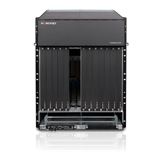
FortiGate-5144C Chassis You can install up to 14 FortiGate-5000 series boards in the 14 slots of the FortiGate-5144C ATCA chassis. The FortiGate-5144C is a 14U 19-inch rackmount ATCA chassis that contains four redundant hot swappable DC power entry Modules (PEMs). The PEMs connect to -48V DC power and supply 400 W to each chassis front slot. The FortiGate- 5144C chassis also includes four hot swappable cooling fan trays that provide 450W of cooling power per slot and a front replaceable air filter with redundant pressure sensors. -
Page 8: Fortigate-5144C Back Panel
The FortiGate-5144C chassis back panel includes four -48V to -60 VDC power entry modules (PEMs). Fortinet ships the FortiGate-5144C chassis with all four installed. The PEMs are divided into two power feeds. PEMs 1 and 2 make up feed A. PEMs 3 and 4 make up power feed B. To provide power to the chassis you must connect the PEMs in feed A. To provide redundant power you can also connect the PEMs in feed B. -
Page 9: Chassis Hardware Information
The back panel also contains 14 RTM slots numbered to correspond to the front panel slots. When the chassis is shipped, these slots are covered by RTM air baffle slot covers. The back panel includes the FortiGate-5144C chassis ground connector that must be connected to ground. Example FortiGate-5144C chassis back panel... -
Page 10: Shipping Components
Eight 4-ft. power cables with 8 AWG stranded wires and double-hole lugs: Black for -48VDC and red for RTN. These cables should only be used to connect the FortiGate-5144C PEMs to a FortiGate-5053B power convertor shelf if purchased with your FortiGate-5144C chassis... - Page 11 Balancing Clustering Ave: 280 Fabric: 40 Gbps or 10 Gbps (SLBC) and FGCP HA *Approximate values, see product datasheets for official values. Any Fortinet ATCA board can be installed in the FortiGate-5144C chassis including the following older models: FortiGate-5001A FortiCarrier-5001A FortiGate-5005FA2 FortiGate-5001FA2...
-
Page 12: Power Requirements
Power requirements The FortiGate-5144C is rated to draw up to 153A. Each of the four PEM feeds/terminals draws up to 39A with -48VDC input and 450W/slot (400W front and 50W RTM). If no RTM slots are used, the total current will be up to 138.5A and with up to 35A per feed with -48VDC input. -
Page 13: Fortigate-5144C Shelf Managers
Button Power OK (Green) Fortinet ships the FortiGate-5144C chassis with the primary shelf manager installed. You can purchase a secondary shelf manager for redundancy. If your chassis has two shelf managers, they support redundant operation with automatic switchover. If both shelf active shelf manager and the other as the backup . -
Page 14: Connecting To The Shelf Manager And Shelf Manager Ethernet Channels
If a failover occurs the active shelf manager's IP address will be transferred to the new active shelf manager. The new backup shelf manager will have the internal IP address of 192.168.1.3. FortiGate-5144C 6.2.3 Chassis Guide... -
Page 15: Shelf Manager Ethernet Connections To Chassis Slots (And Boards)
Because ETH0 connects to both shelf manager front panel Ethernet interface and to the chassis backplane base channel via the shelf manager onboad Ethernet switch, it is possible to create an Ethernet loop if you connect the shelf FortiGate-5144C 6.2.3 Chassis Guide... - Page 16 The default configuration enables BOTH the front panel and the backplane interfaces. disable_backplane_port disables the connection to the backplane. This option is factory set by Fortinet. disable_front_panel_port disables the connection to the front panel Ethernet interface.
-
Page 17: Radial Ipmb Bus Topology
Cut Off) Radial IPMB bus topology The FortiGate-5144C backplane includes a redundant dual star radial IPMB bus for higher reliability. Each shelf manager provides 14 unique IPMB0-A and 14 unique IPMB0-B links to the 14 chassis slots. This means 28 IPMB channels per shelf manager. -
Page 18: Using The Shelf Manager Cli
(48VDC) provides Telco form-c relay connections for minor, major and critical power faults. The cable required to connect to the alarm interface is not supplied by Fortinet. To monitor alarms you should connect to the telco alarm interface of the active shelf alarm panel, which by default is the one on the left. -
Page 19: Air Filter
Air Filter The FortiGate-5144C chassis includes a front replaceable air filter that removes dust from intake air and provides static pressure to achieve uniform airflow. The filter must be installed for the chassis to operate normally. If the air filter is not locked into place the air filter presence sensors cause an alarm. -
Page 20: Cooling Fans, Cooling Air Flow, And Minimum Clearance
Cooling fans, cooling air flow, and minimum clearance The FortiGate-5144C chassis contains four hot-swappable cooling fans (fan 1 to fan 4) installed in the fan cabinet at the top of the chassis. Two fans are access able from the front of the chassis and two from the back. - Page 21 FortiGate-5144C Chassis Fortinet Technologies Inc. FortiGate-5144C fan tray LEDs Description H/S (Hot Swap) Normally off. Blinking blue indicates that the fan is starting up. OOS (Out of Service) Normally off. Blinking red indicates the fan is out of service and should be replaced.
-
Page 22: Fortigate-5144C Hardware Procedures
Mount the FortiGate chassis in a rack before installing the FortiGate-5000 boards. The FortiGate-5144C chassis must be mounted in a standard 19-inch rack. The chassis can be mounted in a 4-post rack using the rack mount brackets in the standard front mounting position as they are installed the chassis when it is shipped. -
Page 23: Air Flow
The FortiGate-5144C chassis should not be operated as a free-standing appliance. It is recommended that you mount the FortiGate-5144C chassis near the bottom of the rack to avoid making the rack top-heavy and potentially falling over. If you are going to mount the chassis higher make sure the rack is well anchored. -
Page 24: Installing Forticontroller Or Fortiswitch Boards
The dual dual-star 40Gbps switch fabric backplane is most often used for data communication between boards in the chassis. Base backplane switching is usually used for sync and HA heartbeat communication boards in the. To install FortiController or FortiSwitch boards, see the documentation supplied with the board. FortiGate-5144C 6.2.3 Chassis Guide... -
Page 25: Power Connection And Configuration
FortiGate-5144C chassis is designed to be connected directly to this DC power system. The FortiGate-5144C is rated at 48VDC 156A with 4x feeds up to 39A/feed. For each feed, the provision can be with one main breaker rated for 156A or more or four breakers rated at 40A. With a 20% margin, the main breaker should be rated for 187A. -
Page 26: Connecting The Fortigate-5144C Chassis To Dc Power And Ground
Fortinet Technologies Inc. Example: power for a fully-loaded chassis (14 boards) The power requirement for a fully loaded FortiGate-5144C chassis with boards in all 14 slots would be: 1000W + (400W * 14) = 6600W Connecting the FortiGate-5144C chassis to DC power and ground The chassis includes two redundant power feeds (Feed A and Feed B) which provide power to all chassis slots and components. -
Page 27: Crimping Guidelines
Slot 10 Manager 2 To connect the FortiGate-5144C PEMs to DC power you must use power connectors and wires that comply with the local electrical wiring code and the requirements of the facility in which you are installing the FortiGate-5144C chassis. -
Page 28: Connecting Fortigate-5144C Power Feeds To Dc Power
Fortinet Technologies Inc. Connecting FortiGate-5144C power feeds to DC power The following procedure describes how to connect the PEMs in a FortiGate-5144C power feed to DC power. Repeat this procedure to connect each power feed. Eight DC cables are required for the PEMs in a feed (and all terminals of e ach polarity should be used). -
Page 29: Connecting The Fortigate-5144C Chassis To Ground
Connecting the FortiGate-5144C chassis to ground The FortiGate-5144C chassis includes a ground terminal on the rear the bottom of the FortiGate-5144C back panel. The ground terminal provides two connectors to be used with a double-holed lug such as Thomas & Betts PN 54850BE. -
Page 30: Fortigate-5053B Power Supply Shelf And Psu-5000B Power Supplies
1. Attach the ESD wrist strap to your wrist and to an ESD socket or to a bare metal surface on the chassis or frame. 2. Make sure that the chassis and ground wire are not energized. 3. Connect the green ground wire from the local ground to the ground connector on the FortiGate-5144C chassis. 4. Secure the ground wire to the chassis. - Page 31 Guide . As already stated, Fortinet supplies eight 4-ft. power cables with 8 AWG stranded wires and double-hole lugs: Black for - 48VDC and red for RTN. These cables should be used to connect the FortiGate-5144C PEMs to a FortiGate-5053B power supply shelf.
-
Page 32: Power Requirement Guidelines
The base FortiGate-5144C chassis (empty, with four fans, one shelf manager, two shelf alarm modules and two PEMs installed and operating with the fans running at full speed) requires a maximum of 1000 W. Each chassis slot can supply up to 400 W. - Page 33 Connecting a FortiGate-5144C chassis to a single FortiGate-5053B power supply shelf The following procedure describes how to connect power to the primary FortiGate-5144C PEMs using the FortiGate- 5053B power supply shelf. You can repeat this procedure to connect the backup PEMs to a second FortiGate-5053B power supply shelf.
-
Page 34: Connecting The Fortigate-5053B Power Supply Shelf To Ground
An electrostatic discharge (ESD) preventive wrist strap with connection cord. One green 8 AWG stranded wire with listed closed loop double-hole lug suitable for minimum 8 AWG copper wire, such as Thomas & Betts PN 54850BE. FortiGate-5144C 6.2.3 Chassis Guide... -
Page 35: Turning On Fortigate-5144C Chassis Power
Once the FortiGate-5144C chassis is connected to DC power the chassis powers up. If the chassis is operating correctly, the LEDs on the connected PEM(s) and fans should be lit. As well, the LEDs on the FortiGate-5144C shelf manager and shelf alarm modules should be lit. -
Page 36: Shelf Manager Cli
You can connect to the shelf manager CLI by connecting the console cable supplied with your chassis to a management PC console port and to the shelf manager serial port on the shelf manager front panel. FortiGate-5144C 6.2.3 Chassis Guide... -
Page 37: Connecting To The Shelf Manager Cli From An Ethernet Network
Port To connect to the shelf manager CLI 1. Using the USB to RJ-45 RS-232 console cable supplied with your FortiGate-5144C, connect the console port on the shelf manager to a USB port on your management computer. 2. Start a terminal emulation program on the management computer. Use these settings: Baud Rate (bps) 9600 or 115200, Data bits 8, Parity None, Stop bits 1, and Flow Control None. -
Page 38: Changing The Shelf Manager Root Account Password
Output similar to the following appears as the shelf manager reboots: /etc/rc: hostname demo /etc/rc: Restoring password file to factory default 6. Enter the following command to add a new password for the root account: # passwd FortiGate-5144C 6.2.3 Chassis Guide... -
Page 39: The Shelf Manager Command Line Interface Agent (Clia)
IPMB addresses (as well as hardware addresses) on this bus. When you enter shelf manager CLI commands you indicate chassis slot numbers according to their IPMB addresses. The IPMB and hardware addresses are in hexadecimal format. FortiGate-5144C 6.2.3 Chassis Guide... - Page 40 For example, a FortiGate-5001A board with an AMC module is installed in logical slot 4, then at IPMB address 88, there will be FRU 0 (the FortiGate-5001A board) and FRU 1 (the AMC module). FortiGate-5144C chassis component FRU names, IPMB addresses, and hardware addresses FRU name...
-
Page 41: Change Ip Address Of The Primary Shelf Manager
<channel> is the shelf manager channel and can be 1 or 2. <ip_address> is the new IP address in dotted decimal notation. For example: # clia setlanconfig 1 ip 192.168.0.2 Display the shelf manager firmware version # clia version To display a complete list of all information enter version with no other parameters. FortiGate-5144C 6.2.3 Chassis Guide... -
Page 42: List All Frus In The Chassis
Change the speed for a fan tray # clia setfanlevel <IPMB-address> <FRU_id> <speed> <speed> can be from 0 to 14. Display the contents of the system event log (sel) # clia sel Clear the system event log (sel) # clia sel clear FortiGate-5144C 6.2.3 Chassis Guide... -
Page 43: Changing The Shelf Manager Ip Address And Default Gateway
Error: too few parameters Sets the LAN settings parameter: 2 or "auth_enables" 3 or "ip" 6 or "subnet_mask" 7 or "ipv4_hdr_param" 10 or "arp_control" 11 or "arp_interval" 12 or "dft_gw_ip" 14 or "backup_gw_ip" 16 or "community" FortiGate-5144C 6.2.3 Chassis Guide... -
Page 44: Sensor Types
For example, to deactivate a board in physical slot 11 of a chassis (IPMB address 90, logical slot 8), enter: # clia deactivate 90 0 Pigeon Point Shelf Manager Command Line Interpreter Command issued via IPMB, status = 0 (0x0) Command executed successfully You can re-activate this deactivated board with the following command: FortiGate-5144C 6.2.3 Chassis Guide... -
Page 45: Alarm
Alarm date/time: Sun Jun 8 21:56:47 2009 Alarm source: Schroff Carrier Alarm reason: Cooling state alert Clearing the alarm changes the information displayed by the clia alarm command but not the information displayed by the clia alarm info command FortiGate-5144C 6.2.3 Chassis Guide... -
Page 46: Board
The command output includes the hot swap state. M4 is the normal hot swap state. The following table lists the FRU states defined in the PICMG 3.0 specification as follows: PICMG FRU states FRU state Description Not Installed FortiGate-5144C 6.2.3 Chassis Guide... -
Page 47: Clia
# clia fans Pigeon Point Shelf Manager Command Line Interpreter 20: FRU # 6 Current Level: 30 Minimum Speed Level: 0, Maximum Speed Level: 0 Dynamic minimum fan level: 30 20: FRU # 5 Current Level: 30 FortiGate-5144C 6.2.3 Chassis Guide... -
Page 48: Fru
Pigeon Point Shelf Manager Command Line Interpreter 20: FRU # 3, FRU Info Common Header: Format Version = 1 Board Info Area: Version Language Code = 25 Mfg Date/Time = Oct 9 14:02:00 2014 (9873482 minutes since 1996) FortiGate-5144C 6.2.3 Chassis Guide... -
Page 49: Getlanconfig
A string value that contains the MAC address of the default gateway as 6 hexadecimal byte values delimited by ‘:’ symbols. For example, 00 : 1A : a0 : 2F : BC : C6 . FortiGate-5144C 6.2.3 Chassis Guide... -
Page 50: Getthreshold/Threshold
Both raw and processed values are displayed. The following attributes for each sensor are also displayed: IPMB address of the owning IPM controller Sensor number, sensor name and the LUN by which the sensor can be accessed FortiGate-5144C 6.2.3 Chassis Guide... - Page 51 Lower Non-Recoverable Threshold, Raw Data: 0xad Processed data: 2.110600 Volts Upper Non-Critical Threshold, Raw Data: 0xde Processed data: 2.708400 Volts Upper Critical Threshold, Raw Data: 0xe6 Processed data: 2.806000 Volts Upper Non-Recoverable Threshold, Raw Data: 0xee Processed data: 2.903600 Volts FortiGate-5144C 6.2.3 Chassis Guide...
- Page 52 # clia threshold 90 13 Pigeon Point Shelf Manager Command Line Interpreter 90: LUN: 0, Sensor # 13 ("CPU Board Temp") Type: Threshold (0x01), "Temperature" (0x01) Upper Non-Critical Threshold, Raw Data: 0x4b Processed data: 75.000000 degrees C FortiGate-5144C 6.2.3 Chassis Guide...
-
Page 53: Help
[slot_number] boardreset <slot number> busres force <res> busres info [<res>] busres lock <res> busres query [-v] <res> [<target> [noupdate]] busres release <res> busres sendbusfree <res> <target> busres setowner <res> <target> busres unlock <res> FortiGate-5144C 6.2.3 Chassis Guide... - Page 54 [-t] [-d <state>] [ <addr> [ [ lun: ]<sensor id> | <sensor name> ] ] sensordata [-t] [-d <state>] [ <addr> -f <fru id> ] sensordata [-t] [-d <state>] [ <addr> -f amc <amc number> ] sensorread <addr> [ lun: ]<sensor id> session [<-v>] FortiGate-5144C 6.2.3 Chassis Guide...
- Page 55 <addr> <fru_id> user may use: power_supply <N> (valid in 2.x systems only) fan_tray <N> board <N> shm <N> to access the FRU on the specified board fruinfo board 21 8 fruinfo power_supply 4 fruinfo <addr> <fru_id> FortiGate-5144C 6.2.3 Chassis Guide...
-
Page 56: Minfanlevel
This information can be useful for diagnosing system problems. This information can also help Fortinet Support diagnose shelf manager system problems. sel command shows the contents of the SEL on the specified IPM Controller (at IPMB address 20h by default). -
Page 57: Sensor
The sensor type and event/reading type code The Entity ID, Entity Instance of the related entity (the FRU device ID if the sensor is associated with a FRU) Example for slot 11 and sensor 13: # clia sensor 90 13 FortiGate-5144C 6.2.3 Chassis Guide... -
Page 58: Sensordata
All event messages enabled from this sensor Sensor scanning enabled Initial update completed Raw data: 44 (0x2c) Processed data: 44.000000 degrees C Status: 0x00 setthreshold setthreshold <IPMB-address> <sensor-name> <threshold-type> [-r] <value> setthreshold <IPMB-address> [<lun>:]<sensor-number> <threshold-type> [-r] <value> FortiGate-5144C 6.2.3 Chassis Guide... - Page 59 80.000000 degrees C Upper Non-Recoverable Threshold, Raw Data: 0x5a, Processed Data: 90.000000 degrees C # clia setthreshold 9c 0:2 unc 99 Pigeon Point Shelf Manager Command Line Interpreter Threshold set successfully # clia threshold 9c 0:2 FortiGate-5144C 6.2.3 Chassis Guide...
-
Page 60: Shmstatus
This command displays the list of FRUs that appear to have a problem. In the PICMG 3.0 context, problems are defined as FRUs for which the cause of the last hot swap state change is one of the following: Communication Lost Communication lost due to local failure Unexpected deactivation FortiGate-5144C 6.2.3 Chassis Guide... -
Page 61: Switchover
Use this command to add, delete, modify and display RMCP user accounts for a shelf manager. Display all user accounts Enter the following command to display user account information: clia user -v Pigeon Point Shelf Manager Command Line Interpreter 1: "" Channels 0-15 Privilege level: "Administrator" Flags: "IPMI Messaging" FortiGate-5144C 6.2.3 Chassis Guide... - Page 62 Pigeon Point Shelf Manager Command Line Interpreter User 9 added successfuly clia user Pigeon Point Shelf Manager Command Line Interpreter 1: "" Channels 0-15 Privilege level: "Administrator" Flags: "IPMI Messaging" 9: "user_1" Channels 0-15 Privilege level: "Administrator" Flags: "IPMI Messaging" FortiGate-5144C 6.2.3 Chassis Guide...
-
Page 63: Version
For example, enter the following command to change the user name of user account 6 to NEW-password : clia user password 6 NEW-password version clia version This command displays version information for the Shelf Manager software. # clia version FortiGate-5144C 6.2.3 Chassis Guide... -
Page 64: Generating Snmp Traps For Shelf Manager System Events
This section describes how to configure a FortiGate-5000 series chassis shelf manager to send SNMP traps to an SNMP manager. The shelf manger IP address is 172.20.120.150 and the SNMP manager IP address is 172.20.120.11. The SNMP manager does not require MIBs or any special configuration to receive traps from the shelf manager. FortiGate-5144C 6.2.3 Chassis Guide... - Page 65 MAC: 00:1A:A0:2F:BC:C6 For this example, the FortiGate-5000 series chassis is a FortiGate-5144C chassis with a FortiSwitch-5000 series board in logical slot 1, FortiGate-5000 series boards in logical slots 6, 8, 10, and 11. The same settings will work for a FortiGate-5140, FortiGate-5060 or FortiGate-5050 chassis after making adjustments for the slot numbers.
- Page 66 4. Delay PEF and delay alerts for 60 seconds after the system powers up: # clia setpefconfig startup_delay 60 # clia setpefconfig alert_startup_delay 60 5. Add event filter entries. The syntax of the command is: # clia setpefconfig event_filter <entry_number> <flter_configuration> <filter_ FortiGate-5144C 6.2.3 Chassis Guide...
- Page 67 Add filter entry 20 for the FRUs at IPMB address 20 (PEMs, Fans, etc) clia setpefconfig event_filter 20 80 1 5 02 20 FF FF FF FF FF FF 0 0 0 0 0 0 0 0 0 FortiGate-5144C 6.2.3 Chassis Guide...
-
Page 68: Testing The Configuration
(in red below) and the variable bindings fields (in blue). Byte 2 of the specific trap field shows the sensor type (f0 = hot swap) and the 4th byte is the event offset (06 = assertion to state 6= M6). The variable bindings fields which are in bold in the trace below are the following bytes: FortiGate-5144C 6.2.3 Chassis Guide... - Page 69 00a0 74 20 61 6c 65 72 74 20 6d 65 73 73 61 67 65 00 t alert message. 00b0 c1 Some releases of the Shelf Manager allow selecting between three PET formats. The values are defined as follows: FortiGate-5144C 6.2.3 Chassis Guide...
-
Page 70: Removing And Inserting A Fan Tray
# sec.name source community com2sec local localhost yourwritecommunity com2sec mynetwork default yourreadcommunity 4. Change yourwritecommunity and yourreadcommunity to your write and read community strings. 5. enter :wq to save the file and quit the vi editor. FortiGate-5144C 6.2.3 Chassis Guide... -
Page 71: Using The Shelf Manager System Event Log (Sel)
ATCA slot 1 = IPMC address 82 ATCA slot 14 = IPMC address 9C Logical IPMC from Active Shelf Manager = IPMC address 20 The IPMC connects to and monitors the readings on various sensors located on devices in the system. These FortiGate-5144C 6.2.3 Chassis Guide... -
Page 72: Alarm Leds
Every time an event occurs in a chassis, the respective IPMC controller sends notification to the shelf manager that the event has happened and an entry is added to the SEL. The log entry that is created depends on the sensor that triggered the event and the type of data that the sensor reads. FortiGate-5144C 6.2.3 Chassis Guide... -
Page 73: Clearing Sel Logs
–v after many of the Shelf Manager commands or running the sensordata , Threshold , and Fruinfo commands to get more detailed information on each sensor and FRU device. Clearing SEL logs Use the following command to clear SEL logs: # clia sel clear FortiGate-5144C 6.2.3 Chassis Guide... -
Page 74: Example Ipmc Log Output
Hot Swap State: M7 (Communication Lost), Previous: M5 (Deactivation Request), Last State Change Cause: Unknown (0xf) 9a: Entity: (0xa0, 0x60) Maximum FRU device ID: 0x00 Hot Swap State: M7 (Communication Lost), Previous: M5 (Deactivation Request), Last State Change Cause: Unknown (0xf) FortiGate-5144C 6.2.3 Chassis Guide... -
Page 75: Example Fru Log Output
Normal State Change (0x0) Device ID String: "FanTray3" 20: FRU # 6 Entity: (0x1e, 0x63) Hot Swap State: M4 (Active), Previous: M3 (Activation In Process), Last State Change Cause: Normal State Change (0x0) Device ID String: "FanTray4" FortiGate-5144C 6.2.3 Chassis Guide... -
Page 76: Example Sensor Log Output
Belongs to entity (0xf0, 96): [FRU # 0] 10: LUN: 0, Sensor # 129 ("Reboot Reason") Type: Discrete (0x6f), "OEM reserved" (0xdd) Belongs to entity (0xf0, 96): [FRU # 0] 10: LUN: 0, Sensor # 230 ("Eth Switch Link2") FortiGate-5144C 6.2.3 Chassis Guide... - Page 77 Belongs to entity (0xf2, 96): [FRU # 1] 20: LUN: 0, Sensor # 3 ("FRU 2 HOT_SWAP") Type: Discrete (0x6f), "Hot Swap" (0xf0) Belongs to entity (0xf2, 97): [FRU # 2] 20: LUN: 0, Sensor # 4 ("FRU 3 HOT_SWAP") FortiGate-5144C 6.2.3 Chassis Guide...
- Page 78 Belongs to entity (0xf0, 1): [FRU # 0] 20: LUN: 0, Sensor # 17 ("IPMB LINK 6") Type: Discrete (0x6f), "IPMB Link" (0xf1) Belongs to entity (0xf0, 1): [FRU # 0] 20: LUN: 0, Sensor # 18 ("IPMB LINK 11") FortiGate-5144C 6.2.3 Chassis Guide...
- Page 79 Belongs to entity (0xf0, 1): [FRU # 0] 20: LUN: 0, Sensor # 135 ("FT Oper.Status") Type: Discrete (0x0b), "Management Subsystem Health" (0x28) Belongs to entity (0xf0, 1): [FRU # 0] 20: LUN: 0, Sensor # 136 ("Cooling State") FortiGate-5144C 6.2.3 Chassis Guide...
- Page 80 Belongs to entity (0x1e, 97): [FRU # 4] 20: LUN: 1, Sensor # 154 ("FT2 Feed1 Fuse P") Type: Discrete (0x6f), "Entity Presence" (0x25) Belongs to entity (0x1e, 97): [FRU # 4] 20: LUN: 1, Sensor # 155 ("FT2 Feed2 Fuse P") FortiGate-5144C 6.2.3 Chassis Guide...
- Page 81 Belongs to entity (0x15, 96): [FRU # 7] 20: LUN: 1, Sensor # 166 ("FT3 FW Rev") Type: Discrete (0x6f), "OEM reserved" (0xd6) Belongs to entity (0x1e, 98): [FRU # 5] 20: LUN: 0, Sensor # 166 ("PEM A1 Rev.In1_4") FortiGate-5144C 6.2.3 Chassis Guide...
- Page 82 Belongs to entity (0x15, 97): [FRU # 8] 20: LUN: 0, Sensor # 181 ("PEM A2 FuseFeed1") Type: Discrete (0x6f), "Entity Presence" (0x25) Belongs to entity (0x15, 97): [FRU # 8] 20: LUN: 0, Sensor # 182 ("PEM A2 FuseFeed2") FortiGate-5144C 6.2.3 Chassis Guide...
- Page 83 Belongs to entity (0x15, 98): [FRU # 9] 20: LUN: 0, Sensor # 205 ("PEM B1 In1_4 48V") Type: Discrete (0x6f), "Entity Presence" (0x25) Belongs to entity (0x15, 98): [FRU # 9] 20: LUN: 0, Sensor # 206 ("PEM B1 Rev.In1_4") FortiGate-5144C 6.2.3 Chassis Guide...
- Page 84 Belongs to entity (0x15, 99): [FRU # 10] 20: LUN: 1, Sensor # 224 ("PEM B2 Presence") Type: Discrete (0x6f), "Entity Presence" (0x25) Belongs to entity (0xf0, 1): [FRU # 0] 20: LUN: 0, Sensor # 225 ("PEM B2 In1_4 48V") FortiGate-5144C 6.2.3 Chassis Guide...
- Page 85 Belongs to entity (0x1e, 96): [FRU # 3] 20: LUN: 3, Sensor # 238 ("FT3 ESTD") Type: Discrete (0x6f), "Entity Presence" (0x25) Belongs to entity (0x1e, 98): [FRU # 5] 20: LUN: 0, Sensor # 238 ("FAN4 Exhaust Tem") FortiGate-5144C 6.2.3 Chassis Guide...
- Page 86 Belongs to entity (0x1e, 96): [FRU # 3] 20: LUN: 3, Sensor # 244 ("FT3 WDT STAT") Type: Discrete (0x6f), "Entity Presence" (0x25) Belongs to entity (0x1e, 98): [FRU # 5] 20: LUN: 1, Sensor # 245 ("FT2 WDT STAT") FortiGate-5144C 6.2.3 Chassis Guide...
- Page 87 Belongs to entity (0x1e, 98): [FRU # 5] 20: LUN: 1, Sensor # 253 ("FT2 PWM POL") Type: Discrete (0x6f), "Entity Presence" (0x25) Belongs to entity (0x1e, 97): [FRU # 4] 20: LUN: 3, Sensor # 253 ("FT4 PWM POL") FortiGate-5144C 6.2.3 Chassis Guide...
-
Page 88: Sample Sections Of Sel Output
0x0080: Event: at Jan 1 00:25:25 1970; from:(0x8e,0,0); sensor:(0x01,12); event:0x1(asserted): "Upper Critical", 0x09 0xFF 0xFF The board in ATCA slot 4 has exceeded the CPU board temperature limit: 0x0081: Event: at Jan 1 00:30:40 1970; from:(0x8e,0,0); sensor:(0x01,13); event:0x1(asserted): "Upper Critical", 0x09 0xFF 0xFF FortiGate-5144C 6.2.3 Chassis Guide... -
Page 89: Regulatory Notices, Cautions And Warnings
Le présent appareil numérique n’emet pas de bruits radioélectriques dép¬assant les limites applicables aux appareils numeriques de la classe A préscrites dans le Règlement sur le brouillage radioélectrique édicte par le ministère des Communications du Canada. Voluntary Control Council for Interference (VCCI) – Japan FortiGate-5144C 6.2.3 Chassis Guide Fortinet Technologies Inc. -
Page 90: Bureau Of Standards Metrology And Inspection (Bsmi) - Taiwan
For redundant power sources, connect each to an IEC/UL Listed power source whose output rating is greater than or equal to the equipment. FortiGate-5144C 6.2.3 Chassis Guide... -
Page 91: Safety
Interférence – Si possible, utilisez des câbles Ethernet de paire torsadée blindée (STP) plutôt que de paire torsadée non blindée (UTP). Mechanical loading – To avoid personal injury or damage to the appliance, Fortinet recommends that 2 or more people together install the appliance into the rack. Balance the equipment to avoid uneven mechanical loading and tipping. - Page 92 ESD connector such as the ESD sockets provided on FortiGate- 5000 series chassis. Make sure all FortiGate-5000 series components have reliable grounding. Fortinet recommends direct connections to the building ground.
- Page 93 All non-conductive surfaces on FortiGate-5000 series chassis shall be removed from all threads and connection points to ensure electrical continuity. Unambiguous reference to service documentation for instructions for replacement of fuses replaceable only by service personnel. FortiGate-5144C 6.2.3 Chassis Guide...
- Page 94 Copyright© 2020 Fortinet, Inc. All rights reserved. Fortinet®, FortiGate®, FortiCare® and FortiGuard®, and certain other marks are registered trademarks of Fortinet, Inc., in the U.S. and other jurisdictions, and other Fortinet names herein may also be registered and/or common law trademarks of Fortinet. All other product or company names may be trademarks of their respective owners.
Need help?
Do you have a question about the FortiGate-5144C and is the answer not in the manual?
Questions and answers