AMX MIO R-4 Operation/Reference Manual
Zigbee compatible remote control
Hide thumbs
Also See for MIO R-4:
- Operation/reference manual (274 pages) ,
- Instruction manual (88 pages) ,
- Dimensional drawing (3 pages)

Related Manuals for AMX MIO R-4


Summary of Contents for AMX MIO R-4
- Page 1 Operation/Reference Guide ® Mio Modero ZigBee Compatible Remote Control M i o R e m o t e C on t r ol s L a s t u p d a t e d : 9 / 1 2 / 2 0 0 7...
- Page 2 RMA number. AMX is not liable for any damages caused by its products or for the failure of its products to perform. This includes any lost profits, lost savings, incidental damages, or consequential damages. AMX is not liable for any claim made by a third party or by an AMX Dealer for a third party.
-
Page 3: Table Of Contents
Specifications ... 2 Page Features ... 3 Device Navigation... 3 FCC Compliance ... 3 Mio R-4 Setup ...5 Inserting or Replacing the Lithium-Ion Battery Into the Mio R-4 ... 5 Battery Low Indicator ... 6 Installing Supported Language Keypads ... 6 Device Setup Pages ...9... - Page 4 Updating Firmware ... 32 Updating Mio R-4 Firmware Through USB ... 32 USB ... 33 Prepare your PC for USB communication with the Mio R-4... 33 Configure a Virtual NetLinx Master using NetLinx Studio ... 33 Programming Numbers... 35 Mio R-4...
- Page 5 List Box Commands... 81 Getting The Most From Your Mio Modero R-4 ...89 Overview ... 89 Getting the Most From the Mio R-4 ... 89 The ZigBee Network Calculator... 91 The Mio Modero R-4 Return Button ... 92 Mio Remote Charging Base ...93 Specifications ...
- Page 6 Table of Contents Mio R-4...
-
Page 7: Mio Modero® R-4 Remote
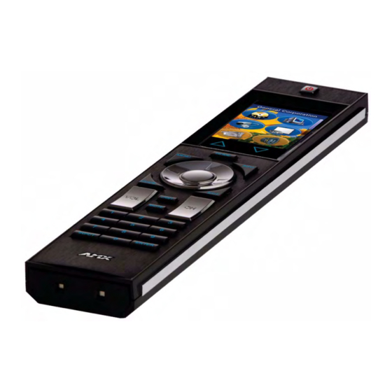
The Mio Modero R-4 remote provides custom control features, contained in an elegant handheld rechargeable device. The Mio R-4 communicates with a NetLinx master via a wireless ZigBee network, making the Mio R-4 a mobile touch panel device. Selecting a source device sends a command to the master and runs predetermined events associated with that source. -
Page 8: Touch And Tilt Sensor
Touch And Tilt Sensor The Mio R-4 wakes up upon touching the chrome side rails, touching the touch screen, or pressing a button. If the remote times out when holding it, you can reawaken the device by tilting it. Errant jostling, such as a bumped table, will not wake the device unless you are holding it. -
Page 9: Page Features
Instruction Manual for details. Device Navigation The Mio R-4 allows you to scroll pages using the up and down buttons beneath the touch screen (FIG. 1). Pressing the Back buttons moves the selection back by one page while holding the button down returns the device to the power up page. - Page 10 Mio Modero® R-4 Remote Mio Modero R-4...
-
Page 11: Mio R-4 Setup
Mio R-4 To install your lithium-ion battery into the Mio R-4: 1. Flip and turn the Mio R-4 so that the buttons are facing away from you and the device is upside down. 2. Holding the device in both hands, place your thumbs on the battery door and slide the battery door free. -
Page 12: Battery Low Indicator
Arabic, French, Italian, or Mandarin Chinese readers. To install a new keypad in one of those four supported languages: 1. Flip and turn the Mio R-4 so that the buttons are facing away from you and the device is upside down. - Page 13 Mio R-4 Setup 9. Place the top assembly back down on the PCB and turn the unit over again, exposing the 6 screw points. 10. Tighten the 6 screw points. 11. Install the battery, replace the battery door, and slide the door to lock it in place.
- Page 14 Mio R-4 Setup Mio Modero R-4...
-
Page 15: Device Setup Pages
Device Setup Pages Overview The Mio R-4 features onboard Setup pages that allow you to set and check the following features: Project Information functions (page 10) Remote & Display Settings (page 11) Date/Time Settings (page 15) Sound Settings (page 17) -
Page 16: Project Information
Project Information The Project Information page displays information specific to the TPDesign4 remote file currently located on the Mio R-4. Use the up and down arrows to scroll from viewable page to page. FIG. 5 Mio R-4 Project Information Pages... -
Page 17: Remote & Display Settings
Remote & Display Settings The device provides you with information concerning current displays settings and allows you to edit the timeout and brightness. Use the up and down arrows to scroll from viewable page to page. FIG. 6 Remote & Display Settings Pages Remote &... -
Page 18: Changing The Remote Timeout
Changing the remote timeout By default, the Mio R-4 will go to sleep at the same time as the selected display timeout if the device is not already in its charging cradle. By disabling this default, the device remains connected to the rest of the ZigBee network while the device is otherwise asleep, and allows a faster response when picked up again. -
Page 19: Raising And Lowering The Lcd Brightness
5. Select the Back button until you are out of the Setup Menu. While deactivating the Sleep on Display Timeout function will prevent the Mio R-4 from going offline when the selected Display Timeout time is reached, doing so will decrease the effective battery life. -
Page 20: Checking Remote Display Settings
Device Setup Pages Checking remote display settings 1. Select Remote & Display Settings from the Setup Page. 2. Use the device’s arrow down to navigate to the fourth and fifth Display Settings pages. 3. Select the Back button until you are out of the Setup Menu. Mio Modero R-4... -
Page 21: Date/Time Settings
Minute Second If the time and date are changed on the Mio R-4 and the device is online with a NetLinx Master, the time and date will also be changed on the NetLinx Master. Getting time and date from your NetLinx Master 1. -
Page 22: Setting The Date Format
Device Setup Pages Setting the date format 1. Select Date/Time Settings from the Setup Page. 2. Use the Up and Down arrows under Date Format to toggle through the formats. The Date Format currently selected is displayed between the arrows. 3. -
Page 23: Sound Settings
3. Push Play Test to test the sound and the volume. The Mio R-4 will allow the Mute button to be selected along with the Button Hit or Button Miss buttons. In this case, the Mute button overrides any sound produced by any of the other buttons. -
Page 24: Battery Settings
Device Setup Pages Battery Settings Check the battery and charging status from this page. FIG. 10 Battery Settings Pages Battery Settings Battery Charge Dock Status Disable Brightness Limit Checking Dock Status 1. Select Battery Settings in the Setup Menu. 2. If the Dock Status button is green, the device is seated correctly in its Mio-RCC charging cradle. If the Dock Status button remains blue, the remote is not in the charging cradle or is not seated correctly in the charging cradle. -
Page 25: Protected Settings Menu
Test Pages Accessing Protected Settings menu items usually requires a password confirmation (FIG. 13). When accessing the Protected Settings for the first time, the Mio R-4 will request a password. The default password is 1988. Changing the password after initial access is highly recommended, and choosing to reset the Mio R-4’s system settings to... -
Page 26: Password Entry
Protected Settings Menu Password Entry The Password Confirmation page protects the device’s system settings, network information and calibration from casual changes. Use the Numeral Keypad pushbuttons (FIG. 1) to enter passwords. The unit allows both numeric and alphanumeric passwords, with different procedures for entering each type. FIG. -
Page 27: Options & Recovery Page
Options & Recovery Page The Options & Recovery page (FIG. 14) enables you to enable page tracking and function identification features, as well as to reset system settings and remove all currently loaded user pages. FIG. 14 Options & Recovery Page Options &... -
Page 28: Toggling The Page Tracking Option
Protected Settings Menu Toggling the Page Tracking option The NetLinx master will track all page flips if the String handler for the device Data event is set in the NetLinx code. 1. Select Options & Recovery in the Protected Settings Menu. 2. -
Page 29: Protection
Protected Settings Menu Protection FIG. 15 Protection Page To enable Front Button Setup Access: 1. Select Options & Recovery in the Protected Settings Menu. 2. Press the Down arrow to access the Protection page (FIG. 15). 3. To enable Front Button Setup Access, press the button, which will turn green. To disable Front Button Setup Access, press the button again to return it to blue. -
Page 30: Edit Passwords
Protected Settings Menu Edit Passwords The Edit Passwords page manages multiple passwords for the device. The first four passwords can be used to protect access to the specific pages in each project. Password 5 is for access to the protected setup pages. -
Page 31: Calibrate
1. Select Calibrate from the Protected Settings Menu. 2. Touch each target that appears on the screen. 3. If successfully calibrated, the Mio R-4 will return you to the Protected Settings Menu. Alternate methods for accessing the calibration page: Press and hold the Input and Back buttons (FIG. 1) for 9 seconds. -
Page 32: System Settings
Protected Settings Menu System Settings The System Settings pages (FIG. 18) provide you with the connection status, gateway selection, and RF link information. Use the device’s up and down arrows to move from page to page. FIG. 18 System Settings Pages Status Status Connected to System... -
Page 33: Checking The Master Ip Address
Checking the master IP address 1. Select Protected Settings in the Setup Menu. 2. Select System Settings in the Protected Settings Menu. The master IP is indicated on the first page. 3. Select the Back button until you are out of the Setup Menu. Checking the gateway IP address 1. -
Page 34: Changing The Master Connection Type
Protected Settings Menu 6. Reboot the Mio R-4 from the Reboot Page (see the Reboot Page section on page 30). In addition to the Abort button, should you decide not to change the Device Number for any reason, press the Back button (FIG. 1) to return to the last page displayed. -
Page 35: Site Survey
Site Survey The Site Survey page (FIG. 19) is a report of the wireless networks found and the status of their availability to the device. Access the Site Survey page from the System Settings page. FIG. 19 Site Survey Page Site Survey PAN ID Join... -
Page 36: Reboot Page
2. Select Reboot Panel. 3. Select Reboot. Test Pages The Test Pages are for testing the Mio R-4’s touchscreen. To check the touchscreen: 1. Select Protected Settings from the Setup Page. 2. Select Test Pages. 3. The subsequent displayed pages are all one color, intended to differentiate touchscreen pixels that may no longer be functioning. -
Page 37: Programming The Mio R-4
1. Set the Mio R-4 communication type to USB. See the Changing the Master Connection Type section on page 28 for details. 2. Flip and turn the Mio R-4 device so that the buttons are facing away from you and the device is upside down. -
Page 38: Downloading Configuration Files Through Tpdesign4
Master Connection Type to Mesh after the download. Downloading Configuration Files through TPDesign4 TPDesign 4 may also be used to download configuration files to the Mio R-4. To download files directly from TPDesign 4: 1. Place the device in the charging cradle and connect the mini USB programming cable (FG10-5965) into the programming jack on the back side of the remote device. -
Page 39: Usb
NetLinx Studio can be set up to run a Virtual Master where the PC acts as the Master by supplying its own IP Address for communication to the Mio R-4. For a PC to establish a USB connection with a Mio R-4, it must have the AMX USBLAN driver installed. - Page 40 11. Right-click on Empty Device Tree/System and select Refresh System to re-populate the list. The Mio R-4 will not appear as a device below the virtual system number (in the Online Tree tab) until both the system number (default = 1) is entered into the Master Connection section of the System Settings page and the Mio R-4 is restarted.
-
Page 41: Programming Numbers
Very Dark Lime Very Light Green Light Green Green Medium Green Dark Green Very Dark Green Very Light Mint Light Mint Mint Medium Mint Dark Mint Very Dark Mint Very Light Cyan Mio Modero R-4 Programming the Mio R-4 Green Blue... - Page 42 Programming the Mio R-4 RGB Values for all 88 Basic Colors (Cont.) Index No. Name Light Cyan Cyan Medium Cyan Dark Cyan Very Dark Cyan Very Light Aqua Light Aqua Aqua Medium Aqua Dark Aqua Very Dark Aqua Very Light Blue...
-
Page 43: Fixed Fonts And Id Numbers
TPDesign4. These values are also listed in the Generate Programmer’s Report. Mio Modero R-4 Green Size Font ID Font type Arial Arial Arial Arial Arial Arial Arial Arial Arial Arial Bold Arial Bold 32 - Variable Fonts start at 32. Programming the Mio R-4 Blue Size... -
Page 44: Slider/Cursor Names
Programming the Mio R-4 Slider/Cursor Names Slider/Cursor Names Bargraph Slider Names None Ball Circle -L Circle -M Circle -S Precision Rectangle -L Rectangle -M Rectangle -S Windows Windows Active Border Styles by Numbers Border styles can be used to program borders on buttons, sliders, and popup pages. - Page 45 Oval H 200x100 Oval V 30x60 Oval V 50x100 Oval V 75x150 Oval V 100x200 Picture Frame Mio Modero R-4 Programming the Mio R-4 Border styles Cursor Left with Hole Cursor Right Cursor Right with Hole Custom Frame Diamond 15...
-
Page 46: Text Effects Names
Programming the Mio R-4 TPD4 Border Styles by Name (Cont.) Border styles Quad Line Single Line Windows Style Popup Windows Style Popup (Status Bar) Menu Bottom Rounded 15 Menu Bottom Rounded 25 Menu Bottom Rounded 35 Menu Bottom Rounded 45... -
Page 47: Send_Commands
SEND_COMMANDs Below is a list of SEND_COMMANDs accepted by the Mio R-4 from NetLinx masters. To use these commands, establish a Telnet session from the PC to the NetLinx master. Additionally, you could use NetLinx Studio 2.4 or the master’s web page to send the commands. - Page 48 Programming the Mio R-4 Page Commands (Cont.) Delete a specific popup page from a specified popup group if it exists. @DPG Delete a popup Syntax: page from a group Variables: • popup page name = 1 - 50 ASCII characters. Name of the popup page.
- Page 49 Toggles the popup page 'Popup1' on the current page from one state to another (On/Off). Mio Modero R-4 SEND_COMMAND <DEV>,"'@PHT-<popup page name>;<hide effect time>'" SEND_COMMAND Device,"'@PHT-Popup1;50'" SEND_COMMAND <DEV>,"'@PPA-<page name>'" SEND_COMMAND Device,"'@PPA-Page1'" SEND_COMMAND <DEV>,"'@PPF-<popup page name>;<page name>'" SEND_COMMAND Device,"'@PPF-Popup1;Main'" SEND_COMMAND Device,"'@PPF-Popup1'" SEND_COMMAND <DEV>,"'@PPG-<popup page name>;<page name>'" SEND_COMMAND Device,"'@PPG-Popup1;Main'" SEND_COMMAND Device,"'@PPG-Popup1'" Programming the Mio R-4...
- Page 50 Programming the Mio R-4 Page Commands (Cont.) Kill a specific popup page from all pages. Kills refers to the deactivating (Off) of a popup @PPK window from all pages. If the pop-up page is part of a group, the whole group is Deactivate a deactivated.
- Page 51 SEND_COMMAND <DEV>,"'@PPT-<popup page name>;<timeout>'" SEND_COMMAND Device,"'@PPT-Popup1;30'" SEND_COMMAND <DEV>,"'@PPX'" SEND_COMMAND Panel,"'@PPX'" SEND_COMMAND <DEV>,"'@PSE-<popup page name>;<show effect name>'" SEND_COMMAND Device,"'@PSE-Popup1;Slide from Left'" SEND_COMMAND <DEV>,"'@PSP-<popup page name>;<x coordinate>,<y coordinate>'" SEND_COMMAND Device,"'@PSP-Popup1;100,0'" SEND_COMMAND <DEV>,"'@PST-<popup page name>;<show effect time>'" SEND_COMMAND Device,"'@PST-Popup1;50'" Programming the Mio R-4...
- Page 52 Programming the Mio R-4 Page Commands (Cont.) Deactivate a specific popup page on either a specified page or the current page. If the PPOF page name is empty, the current page is used (see example 2). If the popup page is part of Deactivate a a group, the whole group is deactivated.
-
Page 53: Button Commands With Embedded Codes
BUT the 0 (zero) is absolute and followed by ’,<left>,<top>’ • ’%JI<alignment of icon 0-9>’ = As shown the above telephone keypad alignment chart, BUT the 0 (zero) is absolute and followed by ’,<left>,<top>’ Programming the Mio R-4... - Page 54 Programming the Mio R-4 "^" Button Commands with Embedded Codes ^BMF (Cont.) For some of these commands and values, refer to theRGB Values for all 88 Basic Colors table on page 35. • ’%CF<on fill color>’ = Set Fill Color.
-
Page 55: Button Commands
ClearG[roup] - Clear popup page group from all pages ClearP[age] - Clear all popup pages from a page with the specified page name ClearA[ll] - Clear all popup pages from all pages SEND COMMAND Device,"'^APF-400,Stan,Main Page'" Programming the Mio R-4... - Page 56 Programming the Mio R-4 "^" Button Commands (Cont.) Append non-unicode text. ^BAT Append Syntax: non-unicode text Variable: • variable text address range = 1 - 4000. • button states range = 1 - 256 for multi-state buttons (0 = All states, for General buttons •...
- Page 57 1 = Off state and 2 = On state). information. SEND_COMMAND Device,"'^BCF-500.504&510.515,1,12'" SEND_COMMAND Device,"'^BCF-500.504&510.515,1,Yellow'" SEND_COMMAND Device,"'^BCF-500.504&510.515,1,#F4EC0A63''" SEND_COMMAND Device,"'^BCF-500.504&510.515,1,#F4EC0A'" "'^BCT-<vt addr range>,<button states range>,<color value>'" 1 = Off state and 2 = On state). information. SEND_COMMAND Device,"'^BCT-500.504&510,1,12'" Programming the Mio R-4...
- Page 58 Programming the Mio R-4 "^" Button Commands (Cont.) Determines what order each layer of the button is drawn. ^BDO Set the button Syntax: draw order Variable: • variable text address range = 1 - 4000. • button states range = 1 - 256 for multi-state buttons (0 = All states, for General buttons •...
- Page 59 IC - Icon JB - Bitmap alignment JI - Icon alignment JT - Text alignment LN - Lines of video removed OP - Opacity TX - Text WW - Word wrap on/off SEND_COMMAND Device,"'^BMC-425,1,1,500,1,BR'" SEND_COMMAND Device,"'^BMC-425,1,1,500,1,%BR'" SEND_COMMAND Device,"'^BMC-150,1,1,315,1,%BR%FT%TX%BM%IC%CF%CT'" Programming the Mio R-4...
- Page 60 Programming the Mio R-4 "^" Button Commands (Cont.) Set any/all button parameters by sending embedded codes and data. ^BMF Set any/all button Syntax: parameters by sending Variables: embedded codes and data • variable text address char array = 1 - 4000.
- Page 61 59 for more information. None, Channel,Invert, ON (Always ON), Momentary, or Blink. (value=255). (value=FF). text format. SEND_COMMAND Device,"'^BMF-500,1,%B10%CFRed%CB Blue %CTBlack%Ptest.png'" "'^BMI-<vt addr range>,<button states range>,<mask image>'" 1 = Off state and 2 = On state). SEND_COMMAND Device,"'^BMI-530,1&2,newMac.png'" Programming the Mio R-4...
- Page 62 Sets the border by number (#10) to those buttons with the variable text range of 500-504 & 510-515. Sets the border by name (AMX Elite) to those buttons with the variable text range of 500-504 & 510-515. The border style is available through the TPDesign4 border-style drop-down list. Refer to theTPD4 Border Styles by Name table on page 38 for more information.
- Page 63 Mio Modero R-4 "'^BRD-<vt addr range>,<button states range>,<border name>'" 1 = Off state and 2 = On state). SEND_COMMAND Device,"'^BRD-500.504&510.515,1&2,Quad Line'" "'^BSF-<vt addr range>,<selection value>'" SEND_COMMAND Device,"'^BSF-500,1'" "'^BSM-<vt addr range>'" SEND_COMMAND Device,"'^BSM-500'" "'^BSP-<vt addr range>,<left>,<top>,<right>,<bottom>'" SEND_COMMAND Device,"'^BSP-530,left,top'" Programming the Mio R-4...
- Page 64 Programming the Mio R-4 "^" Button Commands (Cont.) Set the button word wrap feature to those buttons with a defined address range. By ^BWW default, word-wrap is Off. Set the button word wrap Syntax: feature to those buttons with a...
- Page 65 "'^GDI-<vt addr range>,<bargraph drag increment>'" SEND_COMMAND Device,"'^GDI-7,128'" "'^GIV-<vt addr range>,<joystick axis to invert>'" 0 = Normal 1 = Invert horizontal axis 2 = Invert vertical axis 3 = Invert both axis locations SEND_COMMAND Device,"'^GIV-500,3'" "'^GLH-<vt addr range>,<bargraph hi>'" SEND_COMMAND Device,"'^GLH-500,1000'" Programming the Mio R-4...
- Page 66 Programming the Mio R-4 "^" Button Commands (Cont.) Change the bargraph lower limit. ^GLL Change the Syntax: bargraph lower limit Variable: • variable text address range = 1 - 4000. • bargraph limit range = 1 - 65535 (bargraph lower limit range).
- Page 67 None Arrow Crosshairs Circle Hand Metal Target View Finder SEND_COMMAND Device,"'^GSN-500,Ball'" "'^ICO-<vt addr range>,<button states range>,<icon index>'" 1 = Off state and 2 = On state). SEND_COMMAND Device,"'^ICO-500.504&510.515,1&2,1'" Programming the Mio R-4 Circle -L Precision Rectangle -S Ball Gunsight Spiral...
- Page 68 Programming the Mio R-4 "^" Button Commands (Cont.) Set bitmap/picture alignment using a numeric keypad layout for those buttons with a ^JSB defined address range.The alignment of 0 is followed by ',<left>,<top>'. The left and top Set bitmap/ coordinates are relative to the upper left corner of the button.
- Page 69 1 = Off state and 2 = On state). Zero can be used for an absolute position SEND_COMMAND Device,"'^JST-500.504&510.515,1&2,1'" "'^SHO-<vt addr range>,<command value>'" SEND_COMMAND Device,"'^SHO-500.504&510.515,0'" "'^TEC-<vt addr range>,<button states range>,<color value>'" 1 = Off state and 2 = On state). SEND_COMMAND Device,"'^TEC-500.504&510.515,1&2,12'" Programming the Mio R-4...
- Page 70 Programming the Mio R-4 "^" Button Commands (Cont.) Set the text effect. The Text Effect is specified by name and can be found in TPD4. ^TEF Set the text effect. Syntax: Variable: • variable text address range = 1 - 4000.
-
Page 71: Button Query Commands
// Icon Justification // Font // Text Effect Name // Text Effect Color // Word Wrap // ON state Border Color // ON state Fill Color // ON state Text Color // Border Name // Opacity =',ITOA(CUSTOM.FLAG)" =',CUSTOM.TEXT" Programming the Mio R-4... - Page 72 Programming the Mio R-4 ?Button Query Commands Syntax: ?BCB Get the current border color Variables: • variable text address range = 1 - 4000. • button states range = 1 - 256 for multi-state buttons • custom event type = 1011: Example: Gets the button 'OFF state' border color information.
- Page 73 Text length - Bitmap name text length (should be 9) SEND COMMAND Device,"'?BMP-529,1'" ButtonGet Id = 529 Type = 1002 Flag = 0 VALUE1 = 1 VALUE2 = 9 VALUE3 = 0 TEXT = Buggs.png TEXT LENGTH = 9 Programming the Mio R-4...
- Page 74 Programming the Mio R-4 ? Button Query Commands (Cont.) Syntax: ?BOP Get the overall button opacity. Variables: • variable text address range = 1 - 4000. • button states range = 1 - 256 for multi-state buttons • custom event type = 1015: Example: Gets the button 'OFF state' opacity information.
- Page 75 Value3 - Zero Text - Blank Text length - Zero SEND COMMAND Device,"'?FON-529,1'" ButtonGet Id = 529 Type = 1007 Flag = 0 VALUE1 = 1 VALUE2 =72 VALUE3 = 0 TEXT = TEXT LENGTH = 0 Programming the Mio R-4...
- Page 76 Programming the Mio R-4 ? Button Query Commands (Cont.) Syntax: ?ICO Get the current icon index Variables: • variable text address range = 1 - 4000. • button states range = 1 - 256 for multi-state buttons • custom event type = 1003: Example: Gets the button 'OFF state' icon index information.
- Page 77 Value3 - Zero Text - Blank Text length - Zero SEND COMMAND Device,"'?JST-529,1'" ButtonGet Id = 529 Type = 1004 Flag = 0 VALUE1 = 1 VALUE2 = 1 VALUE3 = 0 TEXT = TEXT LENGTH = 0 Programming the Mio R-4...
- Page 78 Programming the Mio R-4 ? Button Query Commands (Cont.) Syntax: ?TEC Get the current text effect color Variables: • variable text address range = 1 - 4000. • button states range = 1 - 256 for multi-state buttons • custom event type = 1009: Example: Gets the button 'OFF state' text effect color information.
- Page 79 Text length - Button text length SEND COMMAND Device,"'?TXT-529,1'" ButtonGet Id = 529 Type = 1001 Flag = 0 VALUE1 = 1 VALUE2 = 14 VALUE3 = 1 TEXT = This is a test TEXT LENGTH = 14 Programming the Mio R-4...
-
Page 80: Panel Run Time Commands
Programming the Mio R-4 Panel Run Time Commands A device must first be defined in the NetLinx programming language with values or the Device: Port: System (in all programming examples - Panel is used in place of these values)). Serial Commands are used in the AxcessX Terminal Emulator mode. These commands are case insensitive. - Page 81 Sets the brightness level to 70. Mio Modero R-4 SEND_COMMAND <DEV>,"'AKEYR'" SEND_COMMAND Device,"'AKEYR'" SEND_COMMAND <DEV>,"'@AKP-<initial text>;<prompt text>'" SEND_COMMAND Device,"'@AKP-12345678;ENTER PASSWORD'" SEND_COMMAND <DEV>,"'@AKR'" SEND_COMMAND Device,"'@AKR'" SEND_COMMAND <DEV>,"'BEEP'" SEND_COMMAND Device,"'BEEP'" SEND_COMMAND <DEV>,"'BRIT-<brightness level>'" SEND_COMMAND Device,"'BRIT-50'" SEND_COMMAND <DEV>,"'BRIT-<brightness level>'" SEND_COMMAND Device,"'BRIT-70'" Programming the Mio R-4...
- Page 82 Programming the Mio R-4 Panel Run Time Commands (Cont.) Output a double beep. DBEEP Output a double Syntax: beep Example: Outputs a double beep. Extend the keypad. Pops up the keypad icon and initializes the text string to that specified.
- Page 83 Forces the panel out of the screen saver mode. Mio Modero R-4 SEND_COMMAND <DEV>,"'SLEEP'" SEND_COMMAND Device,"'SLEEP'" SEND_COMMAND <DEV>,"'@TKP-<initial text>;<prompt text>'" SEND_COMMAND Device,"'@TKP-999.222.1211;Enter Phone Number'" SEND_COMMAND <DEV>,"'TPAGEON'" SEND_COMMAND Device,"'TPAGEON'" SEND_COMMAND <DEV>,"'TPAGEOFF'" SEND_COMMAND Device,"'TPAGEOFF'" SEND_COMMAND <DEV>,"'@VKB'" SEND_COMMAND Device,"'@VKB'" SEND_COMMAND <DEV>,"'WAKE'" SEND_COMMAND Device,"'WAKE'" Programming the Mio R-4...
-
Page 84: Remote Runtime Commands
Programming the Mio R-4 Remote Runtime Commands A device must first be defined in the NetLinx programming language with values for the Device: Port: System (in all programming examples - Remote is used in place of these values). Remote Runtime Commands... -
Page 85: Input Commands
Example: Set the panel volume to 50. Mio Modero R-4 "'^CAL'" SEND_COMMAND Device,"'^CAL'" SEND_COMMAND <DEV>,"'^MUT-<mute state>'" SEND_COMMAND Device,"'^MUT-1'" SEND_COMMAND <DEV>,"'@PWD-<page flip password>'" SEND_COMMAND Device,"'@PWD-Main'" SEND_COMMAND <DEV>,"'^PWD-<password level>,<page flip password>'" SEND_COMMAND Device,"'^PWD-Main'" SEND_COMMAND <DEV>,"'^VOL-<volume level>'" SEND_COMMAND Device,"'^VOL-50'" Programming the Mio R-4... -
Page 86: Remote Setup Commands
Programming the Mio R-4 Remote Setup Commands A device must first be defined in the NetLinx programming language with values for the Device: Port: System (in all programming examples - Remote is used in place of these values). Remote Setup Commands... -
Page 87: Listboxes
The range is determined by available memory, which is affected by things like how many lists are defined and how many items will be added for each list. List Box Commands The Mio R-4 supports Data List Box Commands. List Box Commands Data List Commands ^LDN Creates a new data list. - Page 88 Programming the Mio R-4 List Box Commands (Cont.) Data List Commands ^LDA Adds a new row to an existing data list. Primary data is required. ^LDR Removes a row from an existing data list ^LDC Clears all rows in a given list Syntax: SEND_COMMAND <DEV>,"'^LDA-<list...
- Page 89 Example (unicode): SEND_COMMAND Device, "'^LDL- 1,1,1,0045006E0074007200790035,004D0075007300690063'" The field located in column 1, in the row with the primary data "Entry5" and in the data list located at the address of 1 is a text value of Music. Programming the Mio R-4...
- Page 90 Programming the Mio R-4 List Box Commands (Cont.) ^LVC Set the table column display order according to the order of the entered column values ^LVF Filter a list by setting what column to use and what string to compare ^LVL...
- Page 91 5 = Forward Sort + Filter 6 = Reverse current + filter 7 = Reverse sort + filter Example: SEND_COMMAND Device,"'^LVO-1,7'" Displays the data list according to the view definitions located at address 1 and filters and reverse sorts the list. Programming the Mio R-4...
- Page 92 Programming the Mio R-4 List Box Commands (Cont.) List View Commands ^LVP Display a new position ^LVS Set the column order for sorting ^LVU Update any view currently looking at this list Display a new position. If the select option is set, then select that position.
- Page 93 Mine’s Not a High Horse 10,2 So Says I Young Pilgrim Saint Simon Fighting in a Sack Pink Bullets Turn a Square Gone for Good Those to Come Programming the Mio R-4 Channel 10,1 10,3 Data Rows 10,4 Displayed Data 10,5 10,6...
- Page 94 Programming the Mio R-4 List Box Command: My Music with Changes "’^LDR-1,0,4’" "’^LDL-1,1,0,5,4’" "’^LDL-1,1,0,6,5’" "’^LDL-1,1,0,7,6’" "’^LDL-1,1,0,8,7’" "’^LDL-1,1,0,9,8’" "’^LDL-1,1,0,10,9’" "’^LVC-2,4’" "’^LVU-2’" Track Artist Number The Shins Chutes Too Narrow Kissing the Lipless The Shins Chutes Too Narrow Mine’s Not a High Horse 10,2...
-
Page 95: Getting The Most From Your Mio Modero R-4
Overview One of the strengths of the Mio Modero R-4 is its flexibility. Not only may a user change the Mio R-4’s basic functionality, such as changing presets, but it also has the capacity for upgrades to add or improve other abilities. - Page 96 Consistent use of borders will also make for a better look and feel. Keep the number of fonts used on the Mio R-4 to a minimum, as each unnecessary font file takes space in the device's memory that could be used for other files or functions.
-
Page 97: The Zigbee Network Calculator
Mio R-4 on the network. -
Page 98: The Mio Modero R-4 Return Button
The Mio Modero R-4 Return Button The Back/Home button on the Mio R-4 (FIG. 1 on page 1) is unique to this device. While the button may be programmed with simple push/release actions in NetLinx, programming a hold action to the button will prevent the Mio R-4 from sending a hold, press, or release message to the master whenever that button is pushed. -
Page 99: Mio Remote Charging Base
Mio Remote Charging Base The Mio remotes are complemented with the Mio-RCC charging base (FG147-02). Begin with Charging The Mio Remote with Charging Base for the Mio-RCC charging base (FG147-02). FIG. 24 Mio-RCC Charging Base Specifications (Bottom View) (Top View) FIG. -
Page 100: Charging The Mio Remote With Charging Base
Mio-RCC Remote Charging Base (FG147-02) Specifications Dimensions (HWD) Weight Other AMX Equipment: • Mio R-1 (FG147) Charging The Mio Remote with Charging Base The Mio remotes receive power for charging from a charging base. 1. Connect the terminal end of the power supply to the bottom external power port on the Mio remote charging base. - Page 101 Mio Remote Charging Base Mio Modero R-4...
- Page 102 It’s Your World - Take Control™ 3000 RESEARCH DRIVE, RICHARDSON, TX 75082 USA • 800.222.0193 • 469.624.8000 • 469-624-7153 fax • 800.932.6993 technical support • www.amx.com...
Need help?
Do you have a question about the MIO R-4 and is the answer not in the manual?
Questions and answers