AMX Mio Modero R-4 Operation/Reference Manual
Amx corporation zigbee compatible remote control operation/reference guide
Hide thumbs
Also See for Mio Modero R-4:
- Operation/reference manual (102 pages) ,
- Instruction manual (88 pages) ,
- Dimensional drawing (3 pages)
Table of Contents
Advertisement
Quick Links
Download this manual
See also:
Instruction Manual
Advertisement
Table of Contents

Related Manuals for AMX Mio Modero R-4


Summary of Contents for AMX Mio Modero R-4
- Page 1 Operation/Reference Guide ® Mio Modero ZigBee Pro Remote Control M i o R e m o t e C on t r ol s L a s t u p d a t e d : 8 / 2 2 / 2 0 1 1...
- Page 2 RMA number. AMX is not liable for any damages caused by its products or for the failure of its products to perform. This includes any lost profits, lost savings, incidental damages, or consequential damages. AMX is not liable for any claim made by a third party or by an AMX Dealer for a third party.
-
Page 3: Table Of Contents
Table of Contents Mio Modero® R-4 Remote ...1 Overview ... 1 Touch And Tilt Sensor ... 2 Specifications... 2 Display Features ... 3 Device Navigation... 3 FCC Compliance ... 4 Patents... 4 Mio R-4 Setup ...5 Installing or Replacing the Mio R-4 Lithium-Ion Battery... 5 Battery Low Indicator ... - Page 4 Table of Contents Toggling Brightness Limit... 18 Protected Settings Menu ...19 Overview ... 19 Password Entry ... 20 Entering a numeric password ... 20 Entering an alphanumeric password... 20 Options & Recovery Page ... 21 Checking the device number... 21 Toggling the Function Show option ...
- Page 5 Programming Numbers... 35 Fixed Fonts and ID numbers ... 37 Slider/Cursor Names ... 38 Border Styles by Numbers ... 38 Text Effects Names... 40 SEND_COMMANDs ... 41 Page Commands ... 41 PAGE... 41 @APG ... 41 @CPG ... 41 @DPG ... 42 @PDR ...
- Page 6 Table of Contents ^BFB... 52 ^BIM... 52 ^BMC ... 53 ^BMF... 54 ^BMI... 55 ^BMP ... 56 ^BOR... 56 ^BPP... 56 ^BRD ... 57 ^BSF... 57 ^BSM... 57 ^BSP... 57 ^BWW ... 58 ^CPF... 58 ^DPF ... 58 ^ENA... 58 ^FON ...
- Page 7 @VKB ... 77 WAKE... 77 Remote Setup Commands... 78 ^MUT ... 78 @PWD ... 78 ^PWD... 78 Listboxes... 79 List Box Commands... 79 ^LDN... 79 Getting The Most From Your Mio Modero R-4 ...87 Overview ... 87 Mio R-4 Table of Contents...
- Page 8 Table of Contents Getting the Most From the Mio R-4... 87 The ZigBee Network Calculator ... 89 The Mio Modero R-4 Return Button... 90 Mio Remote Charging Base ...91 Specifications ... 91 Charging The Mio Remote with Charging Base ... 92...
-
Page 9: Mio Modero® R-4 Remote
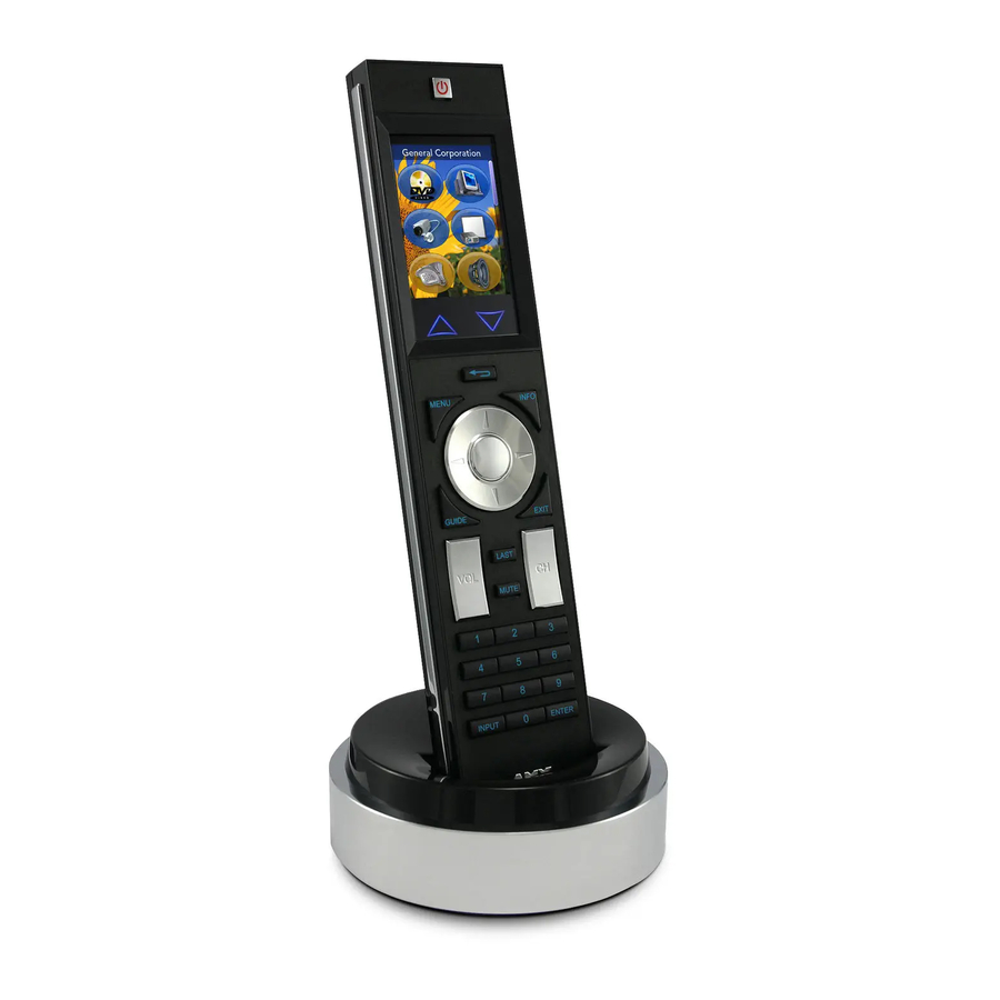
Selecting a source device sends a command to the master and runs predetermined events associated with that source. Selecting a macro will run predefined events, which might not be associated with sources listed, then return the device to its previous mode. Mio Modero R-4 Touch Screen 1 - Power... -
Page 10: Touch And Tilt Sensor
Specifications The Mio Modero R-4 remote specifications are as follows: Mio Modero R-4 (FG148-04) Specifications Dimensions (HWD) 9.50" x 2.00" x .74" (241.3 mm x 50.8 mm x 18.80 mm) Weight •... -
Page 11: Display Features
Marquee Text These features can be implemented using TPDesign4 or higher. For details, please refer to the TPDesign4 online help or Instruction Manual, both available from www.amx.com. Device Navigation The Mio R-4 allows you to scroll through pages using the up and down buttons beneath the touch screen. -
Page 12: Fcc Compliance
U.S. Patent No. D 520,495 U.S. Patent No. 7,786,623 This product employs or practices certain features and/or methods of one or more of the following patents: SIPCO, LLC U.S. Patent No. 7,103,511 U.S. Patent No. 6,914,893 U.S. Patent No. 7,697,492 Mio Modero R-4... -
Page 13: Mio R-4 Setup
FIG. 2. Otherwise, the wires may be damaged or the battery door may not close properly. 4. Place the battery door back on the device, and slide the door upwards to lock it in place. Mio Modero R-4 Mio R-4 Setup Programming Port... -
Page 14: Battery Low Indicator
"Battery Very Low" to encourage the user to shut it down. The device will then shut down to prevent a total discharge of the battery. To recharge the battery, insert the Mio R-4 into the Mio Remote Charging Base (see Charging The Mio Remote with Charging Base section on page 92). Mio Modero R-4... -
Page 15: Customized Keypads
4. Unscrew the 6 screw points indicated in FIG. 3. Programming Jack FIG. 3 Internal Mio R-4 Components 5. Turn the unit over so the buttons are facing you. 6. Lift the top assembly away from the PCB. Mio Modero R-4 Customized Keypads 6 Screw Points... - Page 16 9. Place the top assembly back down on the PCB and turn the unit over again, exposing the 6 screw points. 10. Tighten the 6 screw points. 11. Install the battery, replace the battery door, and slide the door to lock it in place. Mio Modero R-4...
-
Page 17: Device Setup Pages
Accessing the Setup Pages To enter Setup Menu: Hold the Input and Back buttons (see FIG. 1) for 6 seconds. Navigate the Setup pages using the onscreen menu selections and the up and down arrows. Mio Modero R-4 Device Setup Pages... -
Page 18: Project Information
The channel number for the charger sensor. The date the control pages were created. The date of the last revision for the control pages. The date of the last save for the control pages. Any additional comments added in the designing application. Mio Modero R-4... -
Page 19: Remote & Display Settings
Power-up Page File System Setup Port Mio Modero R-4 The valid display timeout times are 0, 10, 15, 20, 25, and 30 seconds. The valid sleep timeout times are 0, 3, 5, 10, 15, 30, 60, 120, 180, and 240 ... -
Page 20: Changing The Remote Timeout
The code string chosen by the NetLinx administrator for the unit wake-up. The code string chosen by the NetLinx administrator for the unit sleep mode. The code string chosen by the NetLinx administrator for the unit startup. Mio Modero R-4... -
Page 21: Raising And Lowering The Lcd Brightness
1. Select Remote & Display Settings from the Setup Page. 2. Under Inactivity, use the Up/Down arrows to adjust the page flip time in increments, to a maximum of 240. 3. Select the Back button until you are out of the Setup Menu. Mio Modero R-4 Device Setup Pages... -
Page 22: Checking Remote Display Settings
1. Select Remote & Display Settings from the Setup Page. 2. Use the device’s arrow down to navigate to the fourth and fifth Display Settings pages. 3. Select the Back button until you are out of the Setup Menu. Mio Modero R-4... -
Page 23: Date/Time Settings
3. Select the Back button until you are out of the Setup Menu. Mio Modero R-4 Allows the user to get date and time information from the NetLinx master or to set changes made manually. -
Page 24: Setting The Date Format
3. Use the Up and Down arrow under Hour, Minute and Second to increment each by 1 until correct. Use the Up and Down keys to return to the first Date/Time Settings page. 4. Select the Set button to save your settings. 5. Select the Back button until you are out of the Setup Menu. Mio Modero R-4... -
Page 25: Sound Settings
4. Press the Mute button again until it is no longer green. 5. Select the Back button until you are out of the Setup Menu. Mio Modero R-4 Adjusts the volume of the sound. Silences any button sound. -
Page 26: Battery Settings
The more green lights, the higher the charge. While on the charger, the Battery Charge indicator will always show a full bar of green lights. Indicates whether the device is in the charging cradle. Disables limits on the LCD brightness; this will reduce battery life. Mio Modero R-4... -
Page 27: Protected Settings Menu
Mio R-4’s system settings to factory defaults will return the password to its default as well. Mio Modero R-4 Opens the Options & Recovery Page (page 21) Opens the Edit Passwords page (page 23) -
Page 28: Password Entry
4. When done, press the Enter button on the keypad to return to the main password confirmation page. Goes to the Alphanumeric Password Entry page Clears the entry field Shuts down the Password page without submitting a password Submits the password Mio Modero R-4... -
Page 29: Options & Recovery Page
4. Select the Back button until you are out of the Setup Menu. Mio Modero R-4 The device’s NetLinx Device Number. When enabled, displays the function codes for each button push. -
Page 30: Toggling The Page Tracking Option
The Yes button will be disabled for five seconds after this page opens, with a countdown appearing at the top right of the screen. After the countdown, the Yes button will change from gray to its normal color. Mio Modero R-4... -
Page 31: Enabling Front Button Setup Access
5. Select the Back button until you are out of the Setup Menu. Make sure to save a copy of Password 5 after it is changed. Without access to the password, you cannot access the Protected Settings page. Mio Modero R-4 Protected Settings Menu... -
Page 32: Calibrate
Touch the touchscreen during a reboot (see the Reboot Page section on page 29 for details) and release when the AMX logo disappears from the screen. Hold the Calibrate button until the page flips to a Calibrate Test page. When on that page, a set of crosshairs will go wherever the touch is registered. -
Page 33: System Settings
2. Select System Settings in the Protected Settings Menu. The master IP is indicated on the first page. 3. Select the Back button until you are out of the Setup Menu. Mio Modero R-4 Green light indicates the overall connection is good. -
Page 34: Checking The Gateway Ip Address
In addition to the Abort button, should you decide not to change the Device Number for any reason, press the Back button (FIG. 1) to return to the last page displayed. 7. Select the Back button until you are out of the Setup Menu. Mio Modero R-4... -
Page 35: Site Survey
If you do not make a selection within three seconds, the pop-up page will automatically close in three seconds. 5. Select the Back button until you return to the Setup Menu. Mio Modero R-4 The Personal Area Network ID. The availability of the network. Yes indicates that it is open to join. -
Page 36: Zigbee Diagnostics
The connection quality for transmission. The connection quality for reception. The delay detected in the network connection. This scroll bar shows the progress of finding a ZigBee PAN within range of the device. Continuous scrolling means that the device is connected. Mio Modero R-4... -
Page 37: Reboot Page
The pages run through blue, green, red, white, black, and then blue again. 4. When finished inspecting the colored pages, select the Back button until you are out of the Setup Menu. Mio Modero R-4 Protected Settings Menu... - Page 38 Protected Settings Menu Mio Modero R-4...
-
Page 39: Programming The Mio R-4
AMX software. The programming jack uses a CC-USB Programming cable, USB to mini USB (FG10-5965), which can be ordered from AMX. Make sure the device is situated in the charging cradle before starting download of configuration files. -
Page 40: Downloading Configuration Files Through Tpdesign4
6. Enter the Mio R-4’s Device ID. 7. Select Send. 8. The unit reboots after the upgrade and enters un-archiving mode, during which the AMX logo is displayed and the POWER LED continuously flashes. The unit reboots again after un-archiving with the new firmware running. -
Page 41: Usb
IP Address for communication to the Mio R-4. For a PC to establish a USB connection with a Mio R-4, it must have the AMX USBLAN driver installed. The AMX USBLAN driver for Windows XP can be downloaded as a stand-alone application from www.amx.com. - Page 42 The Connection status turns green after a few seconds to indicate an active USB connection to the PC (Virtual Master). If the System Connection icon does not turn green, check the USB connection and communication settings and refresh the system. Mio Modero R-4...
-
Page 43: Programming Numbers
Very Dark Lime Very Light Green Light Green Green Medium Green Dark Green Very Dark Green Very Light Mint Light Mint Mint Medium Mint Dark Mint Very Dark Mint Very Light Cyan Mio Modero R-4 Programming the Mio R-4 Green Blue... - Page 44 Very Light Magenta Light Magenta Magenta Medium Magenta Dark Magenta Very Dark Magenta Very Light Pink Light Pink Pink Medium Pink Dark Pink Very Dark Pink White Grey1 Grey3 Grey5 Grey7 Grey9 Grey4 Grey6 Grey8 Green Blue Mio Modero R-4...
-
Page 45: Fixed Fonts And Id Numbers
AMX Bold AMX Bold You must import fonts into a TPDesign4 project file. The font ID numbers are assigned by TPDesign4. These values are also listed in the Generate Programmer’s Report. Mio Modero R-4 Green Size Font ID Font type... -
Page 46: Slider/Cursor Names
Border styles 10-11 Picture frame Double line Bevel-S Bevel-M 22-23 Circle 15 24-27 Neon inactive-S 40-41 Diamond 55 Border styles Circle 155 Circle 165 Circle 175 Circle 185 Circle 195 Cursor Bottom Cursor Bottom with Hole Cursor Top Mio Modero R-4... - Page 47 Oval H 60x30 Oval H 100x50 Oval H 150x75 Oval H 200x100 Oval V 30x60 Oval V 50x100 Oval V 75x150 Mio Modero R-4 Programming the Mio R-4 Border styles Cursor Top with Hole Cursor Left Cursor Left with Hole Cursor Right...
-
Page 48: Text Effects Names
• Medium Drop Shadow 6 with outline • Hard Drop Shadow 6 with outline • Medium Drop Shadow 7 with outline • Hard Drop Shadow 7 with outline • Medium Drop Shadow 8 with outline • Hard Drop Shadow 8 with outline Mio Modero R-4... -
Page 49: Send_Commands
Variable: • popup group name = 1 - 50 ASCII characters. Name of the popup group. Example: Clears all popup pages from the popup group 'Group1'. Mio Modero R-4 "'PAGE-<page name>'" SEND_COMMAND Device,"'PAGE-Page1'" SEND_COMMAND <DEV>,"'@APG-<popup page name>;<popup group name>'" SEND_COMMAND Device,"'@APG-Popup1;Group1'"... -
Page 50: Dpg
SEND_COMMAND <DEV>,"'@DPG-<popup page name>;<popup group name>'" SEND_COMMAND Device,"'@DPG-Popup1;Group1'" SEND_COMMAND <DEV>,"'@PDR-<popup page name>;<reset flag>'" 0 = Disable reset flag SEND_COMMAND Device,"'@PDR-Popup1'" SEND_COMMAND <DEV>,"'@PHE-<popup page name>;<hide effect name>'" SEND_COMMAND Panel,"'@PHE-Popup1;Slide Left'" SEND_COMMAND <DEV>,"'@PHP-<popup page name>;<x coordinate>,<y coordinate>'" SEND_COMMAND Device,"'@PHP-Popup1;75,0'" Mio Modero R-4... -
Page 51: Pht
Toggles the popup page 'Popup1' on the 'Main' page from one state to another (On/Off). Example 2: Toggles the popup page 'Popup1' on the current page from one state to another (On/Off). Mio Modero R-4 SEND_COMMAND <DEV>,"'@PHT-<popup page name>;<hide effect time>'" SEND_COMMAND Device,"'@PHT-Popup1;50'"... -
Page 52: Ppk
SEND_COMMAND <DEV>,"'@PPK-<popup page name>'" SEND_COMMAND Device,"'@PPK-Popup1'" SEND_COMMAND <DEV>,"'@PPM-<popup page name>;<mode>'" MODAL converts a previously NonModal popup page to Modal. modal = 1 and non-modal = 0 SEND_COMMAND Device,"'@PPM-Popup1;Modal'" SEND_COMMAND Device,"'@PPM-Popup1;1'" SEND_COMMAND <DEV>,"'@PPN-<popup page name>;<page name>'" SEND_COMMAND Device,"'@PPN-Popup1;Main'" SEND_COMMAND Device,"'@PPN-Popup1'" Mio Modero R-4... -
Page 53: Ppt
• popup page name = 1 - 50 ASCII characters. Name of the page the popup is displayed • show effect time = Given in 1/10ths of a second. Example: Sets the Popup1 show effect time to 5 seconds. Mio Modero R-4 SEND_COMMAND <DEV>,"'@PPT-<popup page name>;<timeout>'" SEND_COMMAND Device,"'@PPT-Popup1;30'" SEND_COMMAND <DEV>,"'@PPX'"... -
Page 54: Ppof
Example 2: Activates the popup page 'Popup1' on the current page. SEND_COMMAND <DEV>,"'PPOF-<popup page name>;<page name>'" SEND_COMMAND Device,"'PPOF-Popup1;Main'" SEND_COMMAND Device,"'PPOF-Popup1'" SEND_COMMAND <DEV>,"'PPOG-<popup page name>;<page name>'" SEND_COMMAND Device,"'PPOG-Popup1;Main'" SEND_COMMAND Device,"'PPOG-Popup1'" SEND_COMMAND <DEV>,"'PPON-<popup page name>;<page name>'" SEND_COMMAND Device,"'PPON-Popup1;Main'" SEND_COMMAND Device,"'PPON-Popup1'" Mio Modero R-4... -
Page 55: Button Commands With Embedded Codes
"^" Button Commands with Embedded Codes ^BMF Set any/all button parameters by sending embedded codes and data. Mio Modero R-4 Syntax: "'^BMF-<vt addr range>,<button states range>,<data>'" Variables: • variable text address char array = 1 - 4000. • button states range = 1 - 256 for multi-state buttons (0 = All states, for General buttons... - Page 56 • ’%ML<max length>’ = Set the maximum length of a text area. • ’%MK<input mask>’ = Set the input mask of a text area. Example: SEND_COMMAND Device,"'^BMF-500,1,%B10%CFRed%CB Blue %CTBlack%Ptest.png'" Sets the button OFF state as well as the Border, Fill Color, Border Color, Text Color, and Bitmap. Mio Modero R-4...
-
Page 57: Button Commands
• page flip action = • page name = 1 - 50 ASCII characters. Example: Assigns a button to a standard page flip with page name 'Main Page'. Mio Modero R-4 "'^ANI-<vt addr range>,<start state>,<end state>,<time>'" SEND_COMMAND Panel,"'^ANI-500,1,25,100'" "'^APF-<vt addr range>,<page flip action>,<page name>'"... -
Page 58: Bat
SEND_COMMAND Device,"'^BAT-520,1,Enter City'" "'^BAU-<vt addr range>,<button states range>,<unicode text>'" 1 = Off state and 2 = On state). format. SEND_COMMAND Device,"'^BAU-520,1,00770062'" "'^BCB-<vt addr range>,<button states range>,<color value>'" 1 = Off state and 2 = On state). information. SEND_COMMAND Device,"'^BCB-500.504&510,1,12'" Mio Modero R-4... -
Page 59: Bcf
Sets the Off state border color to 12 (Yellow). Colors can be set by Color Numbers, Color name, R,G,B,alpha colors (RRGGBBAA) and R, G & B colors values (RRGGBB). Mio Modero R-4 "'^BCF-<vt addr range>,<button states range>,<color value>'" 1 = Off state and 2 = On state). -
Page 60: Bdo
= 4 Border Layer = 5 Note: The layer assignments are from bottom to top. The default draw order is 12345. SEND_COMMAND Device,"'^BDO-530,1&2,51432'" SEND_COMMAND Device,"'^BDO-1,0,12345'" "'^BFB-<vt addr range>,<feedback type>'" SEND_COMMAND Remote,"'^BFB-500,Momentary'" "'^BIM-<vt addr range>,<input mask>'" SEND_COMMAND Device,"'^BIM-500,AAAAAAAAAA'" Mio Modero R-4... -
Page 61: Bmc
315 onto the OFF state border, font, Text, bitmap, icon, fill color and text color of the button with a variable text address of 150. Mio Modero R-4 "'^BMC-<vt addr range>,<button states range>,<source port>,<source address>,<source state>,<codes>'"... -
Page 62: Bmf
Zero can be used for an absolute position BUT the 0 (zero) is absolute and followed by ’,<left>,<top>’ alignment chart BUT the 0 (zero) is absolute and followed by ’,<left>,<top>’ BUT the 0 (zero) is absolute and followed by ’,<left>,<top>’ Mio Modero R-4... -
Page 63: Bmi
• mask image = Graphic file used. Example: Sets the button with variable text 530 ON/OFF state mask image to 'newmac.png'. Mio Modero R-4 For some of these commands and values, refer to theRGB Values for all 88 Basic Colors table on page 35. -
Page 64: Bmp
Sets the border by number (#10) to those buttons with the variable text range of 500-504 & 510-515. Sets the border by name (AMX Elite) to those buttons with the variable text range of 500-504 & 510-515. The border style is available through the TPDesign4 border-style drop-down list. Refer to theTPD4 Border Styles by Name table on page 38 for more information. -
Page 65: Brd
• bottom = bottom of page. Example: Sets the button with variable text 530 in the left side top of page. Mio Modero R-4 "'^BRD-<vt addr range>,<button states range>,<border name>'" 1 = Off state and 2 = On state). SEND_COMMAND Device,"'^BRD-500.504&510.515,1&2,Quad Line'"... -
Page 66: Bww
ClearG[roup] - Clear popup page group from all pages ClearP[age] - Clear all popup pages from a page with the specified page name ClearA[ll] - Clear all popup pages from all pages SEND COMMAND Device,"'^DPF-409,Prev'" "'^ENA-<vt addr range>,<command value>'" SEND_COMMAND Device,"'^ENA-500.504&510.515,0'" Mio Modero R-4... -
Page 67: Fon
• bargraph limit range = 1 - 65535 (bargraph upper limit range). Example: Changes the bargraph upper limit to 1000. Mio Modero R-4 "'^FON-<vt addr range>,<button states range>,<font value>'" 1 = Off state and 2 = On state). SEND_COMMAND Device,"'^FON-500.504&510.515,1&2,4'"... -
Page 68: Gll
Changes the bargraph or joystick slider color to Yellow. "'^GLL-<vt addr range>,<bargraph low>'" SEND_COMMAND Device,"'^GLL-500,150'" "'^GRD-<vt addr range>,<bargraph ramp down time>'" SEND_COMMAND Device,"'^GRD-500,200'" "'^GRU-<vt addr range>,<bargraph ramp up time>'" SEND_COMMAND Device,"'^GRU-500,100'" "'^GSC-<vt addr range>,<color value>'" SEND_COMMAND Device,"'^GSC-500,12'" Mio Modero R-4... -
Page 69: Gsn
• icon index range = 0 - 9900 (a value of 0 is clear). Example: Sets the icon for On and Off states for buttons with variable text ranges of 500-504 & 510-515. Mio Modero R-4 "'^GSN-<vt addr range>,<bargraph slider name>'" Bargraph Slider Names: None... -
Page 70: Jsb
1 = Off state and 2 = On state). Zero can be used for an absolute position SEND_COMMAND Device,"'^JSB-500.504&510.515,1&2,1'" "'^JSI-<vt addr range>,<button states range>,<new icon alignment>'" 1 = Off state and 2 = On state). Zero can be used for an absolute position SEND_COMMAND Device,"'^JSI-500.504&510.515,1&2,1'" Mio Modero R-4... -
Page 71: Jst
• color value = Refer to theRGB Values for all 88 Basic Colors table on page 35. Example: Sets the text effect color to Very Light Yellow on buttons with variable text 500-504 and 510-515. Mio Modero R-4 "'^JST-<vt addr range>,<button states range>,<new text alignment>'" 1 = Off state and 2 = On state). -
Page 72: Tef
"'^TEF-<vt addr range>,<button states range>,<text effect name>'" 1 = Off state and 2 = On state). effect names. SEND_COMMAND Device,"'^TEF-500.504&510.515,1&2,Soft Drop Shadow 3'" "'^TXT-<vt addr range>,<button states range>,<new text>'" SEND_COMMAND Device,"'^TXT-500.504&510.515,1&2,Test Only'" "'^UNI-<vt addr range>,<button states range>,<unicode text>'" SEND_COMMAND Device,"'^UNI-500,1,0041'" SEND_COMMAND Device,"'^UNI-1,0,0041'" Mio Modero R-4... -
Page 73: Button Query Commands
These fields are populated differently for each query command. The Encode field is not used in any command. Mio Modero R-4 // Text // Bitmap // Icon // Text Justification... -
Page 74: Bcb
Text length - Color name length (should be 9) SEND COMMAND Device,"'?BCF-529,1'" ButtonGet Id = 529 Type = 1012 Flag = 0 VALUE1 = 1 VALUE2 =9 VALUE3 = 0 TEXT = #FF8000FF TEXT LENGTH = 9 Mio Modero R-4... -
Page 75: Bct
Gets the button 'OFF state' bitmap information. The result sent to the Master would be: Mio Modero R-4 SEND_COMMAND <DEV>,"'?BCT-<vt addr range>,<button states range>'" (0 = All states, for General buttons 1 = Off state and 2 = On state). -
Page 76: Bop
Text length - Border name length SEND COMMAND Device,"'?BRD-529,1'" ButtonGet Id = 529 Type = 1014 Flag = 0 VALUE1 = 1 VALUE2 = 22 VALUE3 = 0 TEXT = Double Bevel Raised -L TEXT LENGTH = 22 Mio Modero R-4... -
Page 77: Bww
Gets the button 'OFF state' font type index information. The result sent to the Master would be: Mio Modero R-4 SEND_COMMAND <DEV>,"'?BWW-<vt addr range>,<button states range>'" (0 = All states, for General buttons 1 = Off state and 2 = On state). -
Page 78: Ico
Value3 - Zero Text - Blank Text length - Zero SEND COMMAND Device,"'?JSB-529,1'" ButtonGet Id = 529 Type = 1005 Flag = 0 VALUE1 = 1 VALUE2 = 5 VALUE3 = 0 TEXT = TEXT LENGTH = 0 Mio Modero R-4... -
Page 79: Jsi
Gets the button 'OFF state' text justification information. The result sent to the Master would be: Mio Modero R-4 SEND_COMMAND <DEV>,"'?JSI-<vt addr range>,<button states range>'" (0 = All states, for General buttons 1 = Off state and 2 = On state). -
Page 80: Tec
Text length - Text effect name length SEND COMMAND Device,"'?TEF-529,1'" ButtonGet Id = 529 Type = 1008 Flag = 0 VALUE1 = 1 VALUE2 = 18 VALUE3 = 0 TEXT = Hard Drop Shadow 3 TEXT LENGTH = 18 Mio Modero R-4... -
Page 81: Txt
Example: Gets the button 'OFF state' text information. The result sent to the Master would be: Mio Modero R-4 SEND_COMMAND <DEV>,"'?TXT-<vt addr range>,<button states range>,<optional index>'" (0 = All states, for General buttons 1 = Off state and 2 = On state). -
Page 82: Remote Run Time Commands
'AKEYB', 'AKEYP', 'PKEYP', @AKB, @AKP, @PKP, @EKP, or @TKP commands. Remove the Keyboard or Syntax: Keypad Example: Removes the Keyboard/Keypad. SEND_COMMAND <DEV>,"'ABEEP'" SEND_COMMAND Device,"'ABEEP'" SEND_COMMAND <DEV>,"'ADBEEP'" SEND_COMMAND Device,"'ADBEEP'" SEND_COMMAND <DEV>,"'AKEYR'" SEND_COMMAND Device,"'AKEYR'" SEND_COMMAND <DEV>,"'@AKP-<initial text>;<prompt text>'" SEND_COMMAND Device,"'@AKP-12345678;ENTER PASSWORD'" SEND_COMMAND <DEV>,"'@AKR'" SEND_COMMAND Device,"'@AKR'" Mio Modero R-4... -
Page 83: Beep
Syntax: Variables: • initial text = 1 - 50 ASCII characters. Example: Pops up the Keypad and initializes the text string '123456789' in '*'. Mio Modero R-4 SEND_COMMAND <DEV>,"'BEEP'" SEND_COMMAND Device,"'BEEP'" "'BRIT-<brightness level>'" SEND COMMAND Device,"'BRIT-50'" SEND_COMMAND <DEV>,"'DBEEP'" SEND_COMMAND Device,"'DBEEP'"... -
Page 84: Pkp
Example: Turns Off page tracking. SEND_COMMAND <DEV>,"'@PKP-<initial text>;<prompt text>'" SEND_COMMAND Device,"'@PKP-1234567;ENTER PASSWORD'" SEND_COMMAND <DEV>,"'SETUP'" SEND_COMMAND Device,"'SETUP'" SEND_COMMAND <DEV>,"'SLEEP'" SEND_COMMAND Device,"'SLEEP'" SEND_COMMAND <DEV>,"'@TKP-<initial text>;<prompt text>'" SEND_COMMAND Device,"'@TKP-999.222.1211;Enter Phone Number'" SEND_COMMAND <DEV>,"'TPAGEON'" SEND_COMMAND Device,"'TPAGEON'" SEND_COMMAND <DEV>,"'TPAGEOFF'" SEND_COMMAND Device,"'TPAGEOFF'" Mio Modero R-4... -
Page 85: Input Commands
System. In all programming examples, Remote is used in place of these values. Input Commands ^CAL Syntax: Put remote in calibration mode. Example: Puts the remote in calibration mode. Mio Modero R-4 SEND_COMMAND <DEV>,"'@VKB'" SEND_COMMAND Device,"'@VKB'" SEND_COMMAND <DEV>,"'WAKE'" SEND_COMMAND Device,"'WAKE'" "'^CAL'" SEND_COMMAND Device,"'^CAL'" Programming the Mio R-4... -
Page 86: Remote Setup Commands
• page flip password = 1 - 50 ASCII characters. Example: Sets the page flip password on Password Level 1 'Main'. SEND_COMMAND <DEV>,"'^MUT-<mute state>'" SEND_COMMAND Device,"'^MUT-1'" SEND_COMMAND <DEV>,"'@PWD-<page flip password>'" SEND_COMMAND Device,"'@PWD-Main'" SEND_COMMAND <DEV>,"'^PWD-<password level>,<page flip password>'" SEND_COMMAND Device,"'^PWD-Main'" Mio Modero R-4... -
Page 87: Listboxes
Creates a new data list. Unique list addresses and names are handled programmatically. Mio Modero R-4 It is up to the program to make sure the list address and name are unique. Syntax: "'^LDN-<list port>,<list address>, <column count>,<list name>'"... - Page 88 Removes the text row with primary data Entry5 from an existing data list at address 1. Syntax: "'^LDC-<list address>'" Variables: • list address = address where data resides Example: SEND_COMMAND Device, "'^LDC-1'" Clears all rows in data list located at address 1. Mio Modero R-4...
- Page 89 Deletes the data list ^LDT Sets the column type for a data list ^LDL Modifies the data in a single column field Mio Modero R-4 Syntax: "'^LDD-<list address>'" Variables: • list address = address where data resides Example: SEND_COMMAND Device, "'^LDD-1'"...
- Page 90 • list port = 1-100. port where data resides • list address = address where data resides Example: SEND_COMMAND Device,"'^LVL-5,my songs'" Sets the data list viewed to my songs and displays it according to the view def- initions located at address 5. Mio Modero R-4...
- Page 91 Display a new position ^LVO Display a data list according to a preset sort/ordering view definition. Mio Modero R-4 Display a new position. If select is set, then select that new position. Syntax: SEND_COMMAND <DEV>,"'^LVM-<view address>,<offset>'" Variables: • view address = the address of the view definition •...
- Page 92 NOTE: This must be called after changes to list data. Syntax: SEND_COMMAND <DEV>,"'^LVU-<view address>'" Variables: • view address = the address of the view definition Example: SEND_COMMAND Device,"'LVU-3'" Updates the data list and displays it according to the view definitions located at address 3. Mio Modero R-4...
- Page 93 "’^LDA-1,0,7,The Shins,Chutes Too Narrow,Pink Bullets,"10,7"’" "’^LDA-1,0,8,The Shins,Chutes Too Narrow,Turn a Square,"10,8"’" "’^LDA-1,0,9,The Shins,Chutes Too Narrow,Gone for Good,"10,9"’" "’^LDA-1,0,10,The Shins,Chutes Too Narrow,Those to Come,"10,10"’" "’^LVC-2,4’" "’^LVU-2’" Mio Modero R-4 Album Title Kissing the Lipless Mine’s Not a High Horse 10,2 So Says I...
- Page 94 The Shins Chutes Too Narrow Turn a Square The Shins Chutes Too Narrow Gone for Good The Shins Chutes Too Narrow Those to Come Displayed Data Album Title Channel 10,1 10,3 Row has been 10,5 removed 10,6 10,7 10,8 10,9 10,10 Mio Modero R-4...
- Page 95 Programming the Mio R-4 Mio Modero R-4...
-
Page 96: Getting The Most From Your Mio Modero R-4
Overview One of the strengths of the Mio Modero R-4 is its flexibility. Not only may a user change the Mio R-4’s basic functionality, such as changing presets, but it also has the capacity for upgrades to add or improve other abilities. - Page 97 Getting The Most From Your Mio Modero R-4 commands at one time over a low bandwidth interface will cause the commands to back up and updates will occur more slowly. Care should be taken when sending device updates to a remote. For instance, many MP3 players constantly send status updates: when a song is being played, the time remaining may be updated once per second along with the song title and artist.
-
Page 98: The Zigbee Network Calculator
The ZigBee Network Calculator The ZigBee Network Calculator, available at http://www.amx.com, is a Microsoft Excel® spreadsheet that gives a base guideline to the number of NetLinx messages that can pass between a ZigBee remote and the gateway under given wireless environmental conditions. By entering the number of Mio R-4... -
Page 99: The Mio Modero R-4 Return Button
Getting The Most From Your Mio Modero R-4 To use the calculator: 1. Enter the number of Mio R-4 devices to be used on the network. 2. Enter the number of hops from the device(s) to the gateway access point. -
Page 100: Mio Remote Charging Base
Begin with Charging The Mio Remote with Charging Base for the Mio-RCC charging base (FG147-02). FIG. 25 Mio-RCC Charging Base Specifications (Bottom View) (Top View) FIG. 26 Mio Remote Charging Base (Top and Bottom view) Mio Modero R-4 Mio Remote Charging Base Rubber feet Angle barrel power connector Charging contacts... -
Page 101: Charging The Mio Remote With Charging Base
Mio-RCC Remote Charging Base (FG147-02) Specifications Dimensions (HWD) Weight Other AMX Equipment: • Mio R-1 (FG147) Charging The Mio Remote with Charging Base The Mio remotes receive power for charging from a charging base. 1. Connect the terminal end of the power supply to the bottom external power port on the Mio remote charging base. - Page 102 Mio Remote Charging Base Mio Modero R-4...
- Page 103 It’s Your World - Take Control™ 3000 RESEARCH DRIVE, RICHARDSON, TX 75082 USA • 800.222.0193 • 469.624.8000 • 469-624-7153 fax • 800.932.6993 technical support • www.amx.com...
Need help?
Do you have a question about the Mio Modero R-4 and is the answer not in the manual?
Questions and answers