AMX MIO-R4 Instruction Manual
Hide thumbs
Also See for MIO-R4:
- Operation/reference manual (274 pages) ,
- Instruction manual (88 pages) ,
- Dimensional drawing (3 pages)

Related Manuals for AMX MIO-R4


Summary of Contents for AMX MIO-R4
- Page 1 IN STR U CT IO N MAN U AL M I O - R 4 M I O M O DE RO R - 4 R E M O TE KI T MI O- R4 MI O- RCC-KIT...
-
Page 2: Important Safety Instructions
COPYRIGHT NOTICE AMX© 2015, all rights reserved. No part of this publication may be reproduced, stored in a retrieval system, or transmitted, in any form or by any means, electronic, mechanical, photocopying, recording, or otherwise, without the prior written permission of AMX. Copyright protection claimed... -
Page 3: Table Of Contents
Specifications ........................9 Display Features ........................ 9 Device Navigation ......................10 FCC Compliance ......................10 Patents..........................10 AMX ............................... 10 SIPCO, LLC ............................10 Mio R-4 Setup ....................11 Installing or Replacing the Mio R-4 Lithium-Ion Battery ..........11 Battery Low Indicator..................... 11 Customized Keypads ...................... - Page 4 Table of Contents Entering a Numeric Password ......................20 Options & Recovery Page ....................20 Checking the Device Number........................ 20 Toggling the Function Show option...................... 20 Toggling the Page Tracking Option ...................... 20 Resetting System Settings........................21 Removing User Pages ........................... 21 Enabling Front Button Setup Access ....................
- Page 5 Table of Contents @PHT ..................................... 30 @PPA ..................................... 30 @PPF...................................... 30 @PPG ..................................... 30 @PPK ..................................... 31 @PPM..................................... 31 @PPN ..................................... 31 @PPT ..................................... 31 @PPX ..................................... 31 @PSE ..................................... 31 @PSP ...................................... 32 @PST ...................................... 32 PPOF......................................32 PPOG ....................................... 32 PPON .......................................
- Page 6 Table of Contents ^TEC ...................................... 46 ?TEC ....................................... 47 ^TEF....................................... 47 ?TEF ....................................... 47 “^” Button Commands with Embedded Codes..................48 ^TXT ...................................... 48 ?TXT....................................... 48 ^UNI ...................................... 48 ^BMF...................................... 49 Remote Run Time Commands ..................50 ABEEP ....................................50 ADBEEP ....................................
- Page 7 Table of Contents Border Styles by Name ............................60 Border Styles by Numbers..........................60 Text Effects Names ......................61 Getting The Most From Your Mio Modero R-4 ..........62 Overview .......................... 62 Getting the Most From the Mio R-4 ................. 62 The ZigBee Network Calculator ......................
-
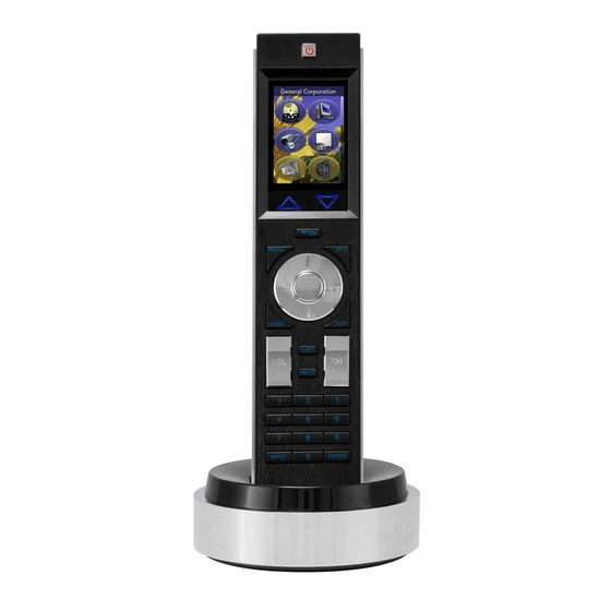
Page 8: Mio Modero® R-4 Remote
You will need TPDesign4 to properly program this device. Both the application and its documentation are available from www.amx.com. Touch And Tilt Sensor The Mio R-4 wakes up upon touching the chrome side rails, touching the touch screen, or pressing a button. -
Page 9: Specifications
Animated Icons List Buttons Marquee Text These features can be implemented using TPDesign4 or higher. For details, please refer to the TPDesign4 online help or Instruction Manual, both available from www.amx.com. Mio Modero R-4 Remote - Instruction Manual... -
Page 10: Device Navigation
Mio Modero® R-4 Remote Device Navigation The Mio R-4 allows you to scroll through pages using the up and down buttons beneath the touch screen. Pressing the Back buttons moves the selection back by one page while holding the button down returns the device to the power up page. FCC Compliance This radio module was tested and certified as a stand-alone device according to FCC Rules CFR 47, Part 15, Subpart C. -
Page 11: Mio R-4 Setup
French, Italian, or Mandarin Chinese readers. The keypad may also be replaced with other keypads to support other functions or arrangements of keys. The additional functions or arrangements are supported with firmware upgrades, available for download at www.amx.com. NOTE: Each of the alternate keypads requires the appropriate f irmware download for proper function; please refer to the Updating Firmware section on page 26 for more information. -
Page 12: Installing Keypads
Mio R-4 Setup Installing Keypads To install a new keypad: Flip and turn the Mio R-4 so that the buttons are facing away from you and the device is upside down. Holding the Mio R-4 in both hands, place your thumbs on the battery door and push up to slide the battery door free. Remove the battery. -
Page 13: Device Setup Pages
Device Setup Pages Device Setup Pages Overview The Mio R-4 features onboard Setup pages that allow you to set and check the following features: Project Information functions (page 13) Remote & Display Settings (page 14) Date/Time Settings (page 16) ... -
Page 14: Viewing Project Information
Device Setup Pages Project Information (Cont.) Build Number The current build version number for the device firmware. Charger Sensor Port The port number for the charger sensor. Charger Sensor Channel The channel number for the charger sensor. Creation Date The date the control pages were created. Revision Date The date of the last revision for the control pages. -
Page 15: Changing The Remote And Display Settings
Device Setup Pages Remote & Display Settings (Cont.) The device serial number Setup Pages Version The current version of the Setup pages uploaded to the unit. Power-up Page The page displayed when the unit powers up. File System The total and available amounts of storage space in the unit. The total amount of available RAM in the unit. -
Page 16: Raising And Lowering The Lcd Brightness
Device Setup Pages NOTE: Make sure to adjust the Sleep Timeout period after disengaging the Sleep on Display Timeout function. From the factory, the default sleep timeout will be set for 15 minutes, but engaging and then disengaging the Sleep on Display Timeout function will reset the period for 0 minutes (will not sleep until the battery charge runs low) because the previous setting will already have 0 for that setting, even though it was not actually used. -
Page 17: Getting Time And Date From Your Netlinx Master
Device Setup Pages Date/Time Settings Get Time & Date Allows the user to get date and time information from the NetLinx master. Time Format Selects between displayed standard and military time formats. Date Format Selects displayed date format. Year Selects the chosen year for the date. Month Selects the chosen month for the date. -
Page 18: Battery Settings
Device Setup Pages Battery Settings Check the battery and charging status from this page. Battery Settings Pages FIG. 10 Battery Settings Battery Charge The quality of the charge is indicated by the number of green lights versus red lights in the display. The more green lights, the higher the charge. -
Page 19: Protected Settings Menu
Use the Numeral Keypad pushbuttons (FIG. 1) to enter passwords. Password Confirmation Page FIG. 13 NOTE: The MIO-R4 allows only numeric passwords. The default password is 1988, which has to be entered in the text entry field upon opening the Password Conf irmation page for the first time. -
Page 20: Entering A Numeric Password
Protected Settings Menu Password Conf irmation (Cont.) Abort Shuts down the Password page without submitting a password Done Submits the password Entering a Numeric Password Select Protected Settings in the Setup Menu. Press any button on the Protected Settings Menu to invoke the Password Conf irmation page. Enter your password from the keypad. -
Page 21: Resetting System Settings
Protected Settings Menu Resetting System Settings Select Options & Recovery in the Protected Settings Menu. Select Reset System Settings. At the page reading “Confirmation: Are sure you want to reset all system settings?”, select Yes to confirm your selection or No to return to the Protected Settings Page (FIG. -
Page 22: Changing The Device Password
Protected Settings Menu Changing the Device Password Select Protected Settings in the Setup Menu. Select Change Passwords on the Protected Settings Menu. Select one of the five passwords to be changed. NOTE: Should you decide to leave the Password Conf irmation page for any reason, press the Exit button (FIG. 1) to return to the last page displayed. -
Page 23: Checking Connection Status
Protected Settings Menu System Settings Status Green light indicates the overall connection is good. Connected to System Shows the number of the connected system. Master IP The IP of the connected master. Icsp Mode The mode used for wireless communication. This is always defaulted to “ZigBee”. Device Number The number of the device in the NetLinx system. -
Page 24: Site Survey
Protected Settings Menu Site Survey The Site Survey page (FIG. 19) is a report of the wireless networks found and the status of their availability to the device. The Site Survey page is accessed by pressing the Network Scan button on the second System Settings page (page 22). Site Survey page FIG. -
Page 25: Reboot Page
Protected Settings Menu RF Link Info (Cont.) Pan ID: The PAN ID number of the device. Channel: The ZigBee channel currently being used by the device. TX Link Quality The connection quality for transmission. RX Link Quality The connection quality for reception. Latency: The delay detected in the network connection. -
Page 26: Programming The Mio R-4
NOTE: Before doing any programming for the Mio R-4, you must download and install the latest AMX USB LAN driver from www.amx.com. The user will be required to install the driver, put the device in USB mode, and connect the device to the computer prior to any upload or download. -
Page 27: Usb
NetLinx Studio can be set up to run a Virtual Master where the PC acts as the Master by supplying its own IP Address for communication to the Mio R-4. For a PC to establish a USB connection with a Mio R-4, it must have the AMX USBLAN driver installed. - Page 28 Programming the Mio R-4 Click the OnLine Tree tab in the Workspace window to view the devices on the Virtual System. 10. Right-click on Empty Device Tree/System and select Refresh System to re-populate the list. The Mio R-4 will not appear as a device below the virtual system number (in the Online Tree tab) until both the system number (default = 1) is entered into the Master Connection section of the System Settings page and the Mio R-4 is restarted.
-
Page 29: Send_Commands
SEND_COMMANDs SEND_COMMANDs Overview Below is a list of SEND_COMMANDs accepted by the Mio R-4 from NetLinx masters. To use these commands, establish a Telnet session from the PC to the NetLinx master. Additionally, you could use NetLinx Studio 2.4 or the master’s web page to send the commands. -
Page 30: Phe
SEND_COMMANDs Page Commands (Cont.) @PHE Set the hide effect for the specified popup page to the named hide effect. Syntax: SEND_COMMAND <DEV>,"'@PHE-<popup page name>;<hide effect name>'" Variables: • popup page name = 1 - 50 ASCII characters. Name of the page the popup is displayed On. •... -
Page 31: Ppk
SEND_COMMANDs Page Commands (Cont.) @PPK Kill a specific popup page from all pages. Kills refers to the deactivating (Off) of a popup window from all pages. If the pop-up page is part of a group, the whole group is deactivated. This command works in the same way as the 'Clear Group' command in TPDesign4. -
Page 32: Psp
SEND_COMMANDs Page Commands (Cont.) @PSP Set the show effect position. Only 1 coordinate is ever needed for an effect, however the command will specify both. This command sets the location at which the effect will begin at. Syntax: SEND_COMMAND <DEV>,"'@PSP-<popup page name>;<x coordinate>,<y coordinate>'" Variable: •... -
Page 33: Button Commands
SEND_COMMANDs Button Commands These Button Commands are used in the NetLinx protocol and are case insensitive. All commands that begin with "^" have the capability of assigning a variable text address range and button state range. A device must f irst be def ined in the NetLinx programming language with values for the Device: Port: System (in all programming examples - Remote is used in place of these values). -
Page 34: Apf
SEND_COMMANDs Button Commands (Cont.) ^APF Add page flip action to a button if it does not already exist. Syntax: "'^APF-<vt addr range>,<page flip action>,<page name>'" Variable: • variable text address range = 1 - 4000. • page flip action = Stan[dardPage] - Flip to standard page Prev[iousPage] - Flip to previous page Show[Popup] - Show Popup page... -
Page 35: Bcb
SEND_COMMANDs Button Commands (Cont.) ?BCB Get the current border color. Syntax: SEND_COMMAND <DEV>,"'?BCB-<vt addr range>,<button states range>'" Variables: • variable text address range = 1 - 4000. • button states range = 1 - 256 for multi-state buttons (0 = All states, for General buttons 1 = Off state and 2 = On state). •... -
Page 36: Bct
SEND_COMMANDs Button Commands (Cont.) ^BCT Set the text color to the specified color only if the specified text color is not the same as the current color. Note: Color can be assigned by color name (without spaces), number or R,G,B value (RRGGBB or RRGGBBAA). Syntax: "'^BCT-<vt addr range>,<button states range>,<color value>'"... -
Page 37: Bim
SEND_COMMANDs Button Commands (Cont.) ^BIM Set the input mask for the specified address. Syntax: "'^BIM-<vt addr range>,<input mask>'" Variable: • variable text address range = 1 - 4000. • input mask = Refer to the Input Commands section on page 52 for character types. Example: SEND_COMMAND Device,"'^BIM-500,AAAAAAAAAA'"... -
Page 38: Bmp
SEND_COMMANDs Button Commands (Cont.) ^BMP Assign a picture to those buttons with a defined address range. Syntax: "'^BMP-<vt addr range>,<button states range>,<name of bitmap/picture>'" Variable: • variable text address range = 1 - 4000. • button states range = 1 - 256 for multi-state buttons (0 = All states, for General buttons 1 = Off state and 2 = On state). •... -
Page 39: Bor
SEND_COMMAND Device,"'^BOR-500.504&510,AMX Elite -M'" Sets the border by name (AMX Elite) to those buttons with the variable text range of 500-504 & 510-515. The border style is available through the TPDesign4 border-style drop-down list. Refer to Border Styles by Numbers on page 60 for more information. -
Page 40: Bsf
SEND_COMMANDs Button Commands (Cont.) ^BSF Set the focus to the text area. Note: Select one button at a time (single variable text address). Do not assign a variable text address range to set focus to multiple buttons. Only one variable text address can be in focus at a time. Syntax: "'^BSF-<vt addr range>,<selection value>'"... -
Page 41: Cpf
SEND_COMMANDs Button Commands (Cont.) ^CPF Clear all page flips from a button. Syntax: "'^CPF-<vt addr range>'" Variables: • variable text address range = 1 - 4000. Example: SEND_COMMAND Remote,"'^CPF-500'" Clears all page flips from the button. ^DPF Delete page flips from button if it already exists. Syntax: "'^DFP-<vt addr range>,<actions>,<page name>'"... -
Page 42: Fon
SEND_COMMANDs Button Commands (Cont.) ?FON Get the current font index. Syntax: SEND_COMMAND <DEV>,"'?FON-<vt addr range>,<button states range>'" Variables: • variable text address range = 1 - 4000. • button states range = 1 - 256 for multi-state buttons (0 = All states, for General buttons 1 = Off state and 2 = On state). •... -
Page 43: Gll
SEND_COMMANDs Button Commands (Cont.) ^GLL Change the bargraph lower limit. Syntax: "'^GLL-<vt addr range>,<bargraph low>'" Variable: • variable text address range = 1 - 4000. • bargraph limit range = 1 - 65535 (bargraph lower limit range). Example: SEND_COMMAND Device,"'^GLL-500,150'" Changes the bargraph lower limit to 150. -
Page 44: Ico
SEND_COMMANDs Button Commands (Cont.) ^ICO Set the icon to a button. Syntax: "'^ICO-<vt addr range>,<button states range>,<icon index>'" Variable: • variable text address range = 1 - 4000. • button states range = 1 - 256 for multi-state buttons (0 = All states, for General buttons 1 = Off state and 2 = On state). •... -
Page 45: Jsb
SEND_COMMANDs Button Commands (Cont.) ?JSB Get the current bitmap justification. Syntax: SEND_COMMAND <DEV>,"'?JSB-<vt addr range>,<button states range>'" Variables: • variable text address range = 1 - 4000. • button states range = 1 - 256 for multi-state buttons (0 = All states, for General buttons 1 = Off state and 2 = On state). •... -
Page 46: Jst
SEND_COMMANDs Button Commands (Cont.) ^JST Set text alignment using a numeric keypad layout for those buttons with a defined address range. The alignment of 0 is followed by ',<left>,<top>'. The left and top coordinates are relative to the upper left corner of the button. Syntax: "'^JST-<vt addr range>,<button states range>,<new text alignment>'"... -
Page 47: Tec
SEND_COMMANDs Button Commands (Cont.) ?TEC Get the current text effect color. Syntax: SEND_COMMAND <DEV>,"'?TEC-<vt addr range>,<button states range>'" Variables: • variable text address range = 1 - 4000. • button states range = 1 - 256 for multi-state buttons (0 = All states, for General buttons 1 = Off state and 2 = On state). •... -
Page 48: Button Commands With Embedded Codes
SEND_COMMANDs Button Commands (Cont.) ^TXT Assign a text string to those buttons with a defined address range. Sets Non-Unicode text. Syntax: "'^TXT-<vt addr range>,<button states range>,<new text>'" Variables: • variable text address range = 1 - 4000. • button states range = 1 - 2 (1 = Off state, 2 = On state). •... -
Page 49: Bmf
SEND_COMMANDs "^" Button Commands with Embedded Codes ^BMF Set any/all button parameters by sending embedded codes and data. Syntax: "'^BMF-<vt addr range>,<button states range>,<data>'" Variables: • variable text address char array = 1 - 4000. • button states range = 1 - 256 for multi-state buttons (0 = All states, for General buttons 1 = Off state and 2 = On state). •... -
Page 50: Remote Run Time Commands
SEND_COMMANDs Remote Run Time Commands A device must first be defined in the NetLinx programming language with values or the Device: Port: System. In all programming examples - Remote is used in place of these values. Serial Commands are used in the AxcessX Terminal Emulator mode. These commands are case insensitive. Remote Run Time Commands ABEEP Output a single beep even if beep is Off. -
Page 51: Ekp
SEND_COMMANDs Remote Run Time Commands (Cont.) @EKP Extend the keypad. Pops up the keypad icon and initializes the text string to that specified. The Prompt Text is optional. Syntax: SEND_COMMAND <DEV>,"'@EKP-<initial text>;<prompt text>'" Variables: • initial text = 1 - 50 ASCII characters. •... -
Page 52: Input Commands
SEND_COMMANDs Remote Run Time Commands (Cont.) @VKB Popup the virtual keyboard. Syntax: SEND_COMMAND <DEV>,"'@VKB'" Example: SEND_COMMAND Device,"'@VKB'" Pops-up the virtual keyboard. WAKE Force the remote out of screen saver mode. Syntax: SEND_COMMAND <DEV>,"'WAKE'" Example: SEND_COMMAND Device,"'WAKE'" Forces the remote out of the screen saver mode. Input Commands A device must first be defined in the NetLinx programming language with values for the Device: Port: System. -
Page 53: Listboxes
SEND_COMMANDs Listboxes Listboxes provide flexibility to remote pages once constrained by physical display areas. Both static and dynamic tables can display multiple devices and items when used with proper navigation tools. List Box commands can be used in conjunction with the application TPDesign4 to create both static and dynamic commands. -
Page 54: Ldc
SEND_COMMANDs Data List Commands (Cont.) ^LDC Clears all rows in a given list. Syntax: "'^LDC-<list address>'" Variables: • list address = address where data resides Example: SEND_COMMAND Device, "'^LDC-1'" Clears all rows in data list located at address 1. ^LDD Deletes the data list Syntax: "'^LDD-<list address>'"... -
Page 55: Lvf
SEND_COMMANDs Data List Commands (Cont.) ^LVF Filter a list by setting what column to use and what string to compare. Note that setting column to zero or data to none makes the filtered ordering the same as sorted ordering. Update must be called for changes to take effect. Syntax: SEND_COMMAND <DEV>,"'^LVF-<view address>,<uniflag>,<column>,<search data>'"... -
Page 56: List View Commands
SEND_COMMANDs Data List Commands (Cont.) ^LVP Display a new position. If the select option is set, then select that position. Syntax: SEND_COMMAND <DEV>,"'^LVP-<view address>,<index>'" Variables: • view address = the address of the view definition • index = the row number in sequential order (first row is 1) Example: SEND_COMMAND Device,"'^LVP-5,3'"... -
Page 57: List Box Command: My Music
SEND_COMMANDs List Box Command: My Music List Box Command: My Music FIG. 24 List Box Command: My Music with Changes List Box Command: My Music with Changes FIG. 25 Mio Modero R-4 Remote - Instruction Manual... -
Page 58: Programming Numbers
SEND_COMMANDs Programming Numbers The following information provides the programming numbers for colors, fonts, and borders. Colors can be used to set the colors on buttons, sliders, and pages. The lowest color number represents the lightest color-specific display; the highest number represents the darkest display. -
Page 59: Fixed Fonts And Id Numbers
Arial Courier New Arial Courier New Arial Courier New Arial AMX Bold Arial AMX Bold Arial Bold AMX Bold Arial Bold 32 - Variable Fonts start at 32. NOTE: You must import fonts into a TPDesign4 project f ile. The font ID numbers are assigned by TPDesign4. These values are also listed in the Generate Programmer’s Report. -
Page 60: Border Styles By Name And Numbers
No. Border styles No. Border styles Border styles None Cursor Right Neon Inactive -L Menu Bottom Rounded 185 AMX Elite -L Cursor Right with Hole 66 Neon Inactive -S Menu Bottom Rounded 195 AMX Elite -M Custom Frame Oval H 60x30... -
Page 61: Text Effects Names
SEND_COMMANDs Text Effects Names The following is a listing of text effects names associated with the ^TEF command. Text Effects • Glow -S • Medium Drop Shadow 1 • Hard Drop Shadow 1 • Glow -M • Medium Drop Shadow 2 •... -
Page 62: Getting The Most From Your Mio Modero R-4
ZigBee was designed for small, low-power devices with minimal bandwidth requirements. The best way to approach the use of AMX ZigBee devices is to treat them as if they were AMX AXLink devices. AXLink devices can only handle a specific amount of data at one time due to bandwidth limitations, and ZigBee devices must be treated in the same way. -
Page 63: The Zigbee Network Calculator
The ZigBee Network Calculator The ZigBee Network Calculator, available at http://www.amx.com, is a Microsoft Excel® spreadsheet that gives a base guideline to the number of NetLinx messages that can pass between a ZigBee remote and the gateway under given wireless environmental conditions. -
Page 64: The Mio Modero R-4 Return Button
Getting The Most From Your Mio Modero R-4 The Mio Modero R-4 Return Button The Back/Home button on the Mio R-4 (FIG. 1 on page 8) is unique to this device. While the button may be programmed with simple push/release actions in NetLinx, programming a hold action to the button will prevent the Mio R-4 from sending a hold, press, or release message to the master whenever that button is pushed. -
Page 65: Mio Remote Charging Base
• 1.15 lbs (.52 kg) - Remote Charging Cradle • .15 lbs (.07 kg) - Power Supply • .06 lbs (.027 kg) - Rechargeable Lithium Battery Other AMX Equipment: • Mio R-1 (FG147) • Mio R-2 RF 418 (FG147-418) • Mio R-2 RF 433 (FG147-433) •... - Page 66 © 2016 Harman. All rights reserved. Modero, NetLinx, AMX, AV FOR AN IT WORLD, and HARMAN, and their respective logos are registered trademarks Last Revised: of HARMAN. Oracle, Java and any other company or brand name referenced may be trademarks/registered trademarks of their respective companies.
Need help?
Do you have a question about the MIO-R4 and is the answer not in the manual?
Questions and answers