Emerson Rosemount 2110 Reference Manual
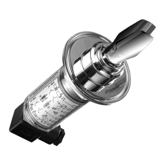
Level switch, vibrating fork
Hide thumbs
Also See for Rosemount 2110:
- Reference manual (38 pages) ,
- Quick start manual (24 pages) ,
- Quick start manual (28 pages)

Related Manuals for Emerson Rosemount 2110


Summary of Contents for Emerson Rosemount 2110
- Page 1 Reference Manual 00809-0100-4029, Rev CA March 2018 ™ Rosemount 2110 Level Switch Vibrating Fork...
- Page 3 The products described in this document are NOT designed for nuclear-qualified applications. Using non-nuclear qualified products in applications that require nuclear-qualified hardware or products may cause inaccurate readings. For information on Rosemount nuclear-qualified products, contact your local Emerson Sales Representative. Title Page...
- Page 4 Reference Manual Title Page 00809-0100-4029, Rev CA March 2018 Title Page...
-
Page 5: Table Of Contents
Reference Manual Contents 00809-0100-4029, Rev CA March 2018 Contents 1Section 1: Introduction 1.1 Safety messages ..............1 1.2 Manual overview . - Page 6 Contents Reference Manual 00809-0100-4029, Rev CA March 2018 AAppendix A: Reference Data A.1 Product Certifications ............. 29 A.2 Ordering Information, Specifications, and Drawings .
-
Page 7: Safety Messages
Process leaks could result in death or serious injury. Install and tighten process connectors before applying pressure. Do not attempt to loosen or remove process connectors while the Rosemount 2110 is in service. Electrical shock could cause death or serious injury. -
Page 8: Manual Overview
Introduction to the Rosemount 2110 The Rosemount 2110 is a liquid point level switch based on the vibrating short fork technology. It is a compact switch with a rugged stainless steel body and forks for use in a wide range of liquid applications. -
Page 9: Measurement Principle
When the Rosemount 2110 is used as a high level alarm, the liquid rises in the tank or pipe making contact with the fork and causing the output state to switch. -
Page 10: Special Features
Heartbeat LED The Rosemount 2110 has a ‘heartbeat’ LED indicating it is operating, and can be seen at all times. The LED flashes when the switch output is ‘off’ and is constantly lit when 'on'. Magnetic test point A magnetic test-point is located on the side of the housing, allowing the user to perform a functional test of the Rosemount 2110 and the system connected to it. -
Page 11: Product Recycling And Disposal
Short forks require minimum intrusion wetside and allow simple low cost installation at any angle into pipes or vessels. Because the Rosemount 2110 projects only 2-in. (50 mm) (depending on connection type), it can be installed in small diameter pipes. By selecting the option of direct load switching electronics, it is ideal for reliable pump control and can be used to protect against pumps running dry. - Page 12 Introduction Reference Manual 00809-0100-4029, Rev CA March 2018 Introduction...
-
Page 13: Safety Messages
Reference Manual Configuration 00809-0100-4029, Rev CA March 2018 Section 2 Installation Safety messages ..............page 7 Considerations before installation . -
Page 14: Considerations Before Installation
2.2.1 Environmental considerations The Rosemount 2110 Level Switch is a wired point level device for use in open or closed tanks, and pipework. The installation must be in a non-hazardous (safe) area. All versions of the level switch are weatherproof and protected against the ingress of dust, but must be protected from flooding. - Page 15 Reference Manual Configuration 00809-0100-4029, Rev CA March 2018 Application limits Check for risk of process medium build-up on the level switch forks. Avoid situations where a drying and coating process medium may create an excessive build-up (see Figure 2-2 on page 9) or implement preventative maintenance programs to ensure the build-up is not enough to impair performance.
-
Page 16: Installation Considerations
(Figure 2-4 on page 11). Device identification To identify the Rosemount 2110 version, see the label on the housing. Mounting orientation Mount the level switch at any angle that allows the liquid level to rise or flow through the fork gap... - Page 17 Mount the level switch in a position to allow easy access to the wiring terminals. Ensure there is sufficient room for making electrical connections. For dimensional drawings, see Appendix A: Reference Data for where to find the latest information. Figure 2-4. Handling the Rosemount 2110 Figure 2-5. Do Not Modify the Rosemount 2110 Configuration...
- Page 18 Installing the level switch near to liquid entering the tank at the fill point. – Heavy splashing on the fork. Extra consideration is needed if the plant vibration is close to the 1300 Hz operating frequency of the Rosemount 2110. Configuration...
-
Page 19: Installation Procedures
Reference Manual Configuration 00809-0100-4029, Rev CA March 2018 Installation procedures 2.3.1 Process connection seals Figure 2-6. Process Connection Seals A. NPT or BSPT (R) thread B. PTFE tape C. Gasket D. BSPP (G) thread E. Tri Clamp F. The Tri Clamp seal is supplied as in as accessory kit (see Appendix A: Reference Data for where to find the latest information). -
Page 20: Correct Fork Alignment
Configuration Reference Manual 00809-0100-4029, Rev CA March 2018 2.3.2 Correct fork alignment Pipe installation Ensure the fork is correctly aligned by using the groove or notch as indicated in Figure 2-7. Figure 2-7. Correct Fork Alignment for Pipe Installation Tri Clamp Threaded Tank installation Figure 2-8. -
Page 21: Mounting The Threaded Versions
Reference Manual Configuration 00809-0100-4029, Rev CA March 2018 2.3.3 Mounting the threaded versions Seal and protect the threads Use anti-seize paste or PTFE tape according to your site procedures. Gasket may be used as a sealant for BSPP (G) threaded connections. Mount the level switch on tank or pipework Threaded tank or pipework connection (vertical installation ... - Page 22 Reference Manual Configuration 00809-0100-4029, Rev CA March 2018 Threaded flange connection Place the customer supplied flange on the tank nozzle. Gasket (customer supplied) Tighten the bolts and nuts with sufficient torque for the flange and gasket. Screw the level switch into the flange thread. Tighten using the hexagon only Gasket for BSPP (G) threads only...
-
Page 23: Mounting The Tri Clamp Versions
Lower the level switch onto the flange face Seal Fit the Tri Clamp Note The Tri Clamp and seal are supplied in an accessory kit that has to be ordered separately. See the Rosemount 2110 Product Data Sheet for ordering information. Configuration... -
Page 24: Electrical Installation
For direct load switching, a DPST (Double Pole, Single Throw) (on/off) switch must also be fitted for safe disconnection of the power supply. Fit the DPST switch as near to the Rosemount 2110 as possible, keeping the switch free of obstructions. Label the switch to indicate it is the supply disconnection device for the Rosemount 2110. - Page 25 The Rosemount 2110 requires a minimum current of 3 mA, which continues to flow when it is ‘off’. When selecting a relay to wire in series with the Rosemount 2110, the drop-out voltage of the relay must be greater than the voltage generated across the relay coil when 3 mA flows through it.
- Page 26 For direct load switching, a DPST (Double Pole, Single Throw) (on/off) switch must also be fitted for safe disconnection of the power supply. Fit the DPST switch as near to the Rosemount 2110 as possible, keeping the switch free of obstructions. Label the switch to indicate it is the supply disconnection device for the Rosemount 2110.
-
Page 27: Wiring
March 2018 2.4.2 Wiring The Rosemount 2110 meets IP66 and IP67 weatherproof ratings when correctly assembled with the supplied connector and suitable cable. Ensure seals are in place to maintain the weatherproof ratings. Note Use only the connector supplied and ensure the cable gland is pointing downwards or sideways. - Page 28 Configuration Reference Manual 00809-0100-4029, Rev CA March 2018 Signal cable shield grounding at power supply end Make sure the instrument cable shield is: Trimmed close and insulated from touching the level switch housing. Connected to the next shield if cable is routed through a junction box. ...
- Page 29 Reference Manual Configuration 00809-0100-4029, Rev CA March 2018 5. Re-fit the plug cover and tighten the cable gland. a. The plug cover can be re-fitted in any one of four positions. Optional positions Fork alignment indicator b. Ensure the cable gland is pointing downwards or sideways. c.
-
Page 30: Led Indication
Reference Manual Configuration 00809-0100-4029, Rev CA March 2018 d. If possible, arrange the wiring with a drip loop. 6. Connect the power supply when ready to apply power. LED Indication Table 2-3. LED Indication LED flash rate Switch status Continuous Output state is on 1 every second Output state is off... -
Page 31: Magnetic Test Point
Normal condition Inspection Visually examine the Rosemount 2110 and do not use if it is damaged. Check that the connector and seals are correctly fitted, and that the connector fixing screw and gland are tight. Ensure the LED flash rate is 1 Hz or constantly on. For anything else, see “LED Indication”... -
Page 32: Maintenance
Installation Reference Manual 00809-0100-4029, Rev CA March 2018 Maintenance Figure 3-2. Maintenance Note Only use a soft type brush for cleaning. Troubleshooting For a malfunction, see “Troubleshooting Chart” on page 26 for possible causes. Table 3-1. Troubleshooting Chart Fault Symptom/indication Action/solution Check the power supply, check the load No LED, no power... -
Page 33: Service Support
To expedite the return process outside of the United States, contact the nearest Emerson representa- tive. Within the United States, call the Emerson Instrument and Valves Response Center using the 1 800 654 7768 toll-free number. This center, available 24 hours a day, will assist you with any needed information or materials. - Page 34 Installation Reference Manual 00809-0100-4029, Rev CA March 2018 Installation...
-
Page 35: A.1 Product Certifications
1. Go to Emerson.com/Rosemount. 2. In the Products section, click Level Measurement and then View Products. Rosemount 2110 Level Switch - Vibrating Fork 3. Click to view the product details page. 4. Scroll as needed to the green menu bar and click Documents &... - Page 36 Reference Manual Specifications and Reference Data March 2018 00809-0100-4029, Rev CA Specifications and Reference Data...
- Page 38 Standard Terms and Conditions of Sale are available upon request. +971 4 8118100 The Emerson logo is a trademark and service mark of Emerson Electric Co. Rosemount is a mark of one of the Emerson family of companies. +971 4 8865465 All other marks are the property of their respective owners.
Need help?
Do you have a question about the Rosemount 2110 and is the answer not in the manual?
Questions and answers