Sirona ORTHOPHOS XG 5 Installation Instructions Manual
Hide thumbs
Also See for ORTHOPHOS XG 5:
- Operating instructions manual (106 pages) ,
- Maintenance manual (30 pages) ,
- Service manual (630 pages)

Related Manuals for Sirona ORTHOPHOS XG 5


Summary of Contents for Sirona ORTHOPHOS XG 5
- Page 1 NMKOMNR kÉï=~ë=çÑW= loqelmelp=ud=R=L=`ÉéÜ fåëí~ää~íáçå=fåëíêìÅíáçåë= English ORTHOPHOS XG 5 / Ceph Prog.
- Page 2 About this document For installation, please refer also to the following documents: This document describes the installation of the • Installation drawings ORTHOPHOS XG 5 panoramic X-ray unit in the following versions: • "Installation Requirements" (separate document) • Operating Instructions •...
-
Page 3: Table Of Contents
Sirona Dental Systems GmbH Installation Instructions ORTHOPHOS XG 5 / Ceph Contents Before you begin ....................... 5 Identification of warnings ................. 6 Safety....................... 7 System versions ..................8 Sensor versions ..................9 Dimensions/Space requirements............10 Mounting options ................... 12 Installation versions ................13 Delivery and transport .................... - Page 4 Sirona Dental Systems GmbH Installation Instructions ORTHOPHOS XG 5 / Ceph Initial startup ........................81 Inserting the forehead and temple supports........... 82 Plugging in the sensor(s) ............... 83 Switching the units ON................84 Checking the data paths ................ 86 Startup for USA/Canada only ..................89 Startup, measurements and controls .............
-
Page 5: Before You Begin
Before you begin ORTHOPHOS XG 5 / Ceph 60 04 902 D 3352 D 3352.031.02.19.02... -
Page 6: Identification Of Warnings
The structure, appearance and use of warning and safety information in Sirona documents are based on the ANSI Z535 standard. The following warnings may be used in this document:... -
Page 7: Safety
Sirona Dental Systems GmbH 1 Before you begin Installation Instructions ORTHOPHOS XG 5 / Ceph 1.2 Safety 1.2 Safety DANGER CAUTION Fixed connection! The unit contains class 1 lasers. The installation of a power plug instead of the A distance of at least 4" (10 cm) between eye and laser must prescribed fixed (hard-wired) connection violates be observed. -
Page 8: System Versions
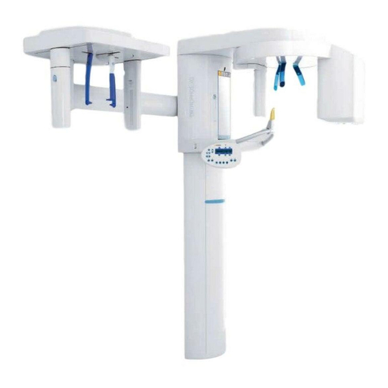
1 Before you begin Sirona Dental Systems GmbH 1.3 System versions Installation Instructions ORTHOPHOS XG 5 / Ceph 1.3 System versions 1. ORTHOPHOS XG 5 Digital unit 2. ORTHOPHOS XG 5 Ceph Digital unit with cephalometer 60 04 902 D 3352... -
Page 9: Sensor Versions
Sirona Dental Systems GmbH 1 Before you begin Installation Instructions ORTHOPHOS XG 5 / Ceph 1.4 Sensor versions 1.4 Sensor versions XG PAN sensor Sensor for panoramic exposures (PAN) XG CEPH sensor Sensor for panoramic and cephalometric (ceph) exposures 60 04 902 D 3352... -
Page 10: Dimensions/Space Requirements
1 Before you begin Sirona Dental Systems GmbH 1.5 Dimensions/Space requirements Installation Instructions ORTHOPHOS XG 5 / Ceph 1.5 Dimensions/Space requirements NOTICE These dimensions apply to installation of the X-ray unit without the floor stand. Installation with the floor stand results in an additional 30 mm (1 3/16") increase of all... - Page 11 Sirona Dental Systems GmbH 1 Before you begin Installation Instructions ORTHOPHOS XG 5 / Ceph 1.5 Dimensions/Space requirements NOTICE The dimensions specified here apply to installation of the X-ray unit without the floor stand. Installation with the floor stand results in an additional 30 mm (1 3/16") increase of...
-
Page 12: Mounting Options
1 Before you begin Sirona Dental Systems GmbH 1.6 Mounting options Installation Instructions ORTHOPHOS XG 5 / Ceph 1.6 Mounting options Standard version Option 1 Option 2 Standard version Option 2: with floor stand (see section 3.3) (see section 3.4) 1. -
Page 13: Installation Versions
Standard installation: Installation version 1 (see section 6.3.1): ORTHOPHOS XG 5/Ceph without remote control ORTHOPHOS XG 5 / Ceph with remote control with release button on the coiled cable in the outside the X-ray room without release button on the treatment room. - Page 14 1 Before you begin Sirona Dental Systems GmbH 1.7 Installation versions Installation Instructions ORTHOPHOS XG 5 / Ceph 60 04 902 D 3352 D 3352.031.02.19.02...
-
Page 15: Delivery And Transport
Delivery and transport ORTHOPHOS XG 5 / Ceph 60 04 902 D 3352 D 3352.031.02.19.02... -
Page 16: Delivery
2 Delivery and transport Sirona Dental Systems GmbH 2.1 Delivery Installation Instructions ORTHOPHOS XG 5 / Ceph 2.1 Delivery Dimensions (cm): 199 x 69 x 122 (inches): 78 3/8 x 30 3/4 x 28 3/4 Weight: 177 kg (390 lbs) •... - Page 17 Make a note on the delivery slip that the indicator is activated. Have this confirmed on the delivery note by the driver of the transport company. Fax the delivery note to the Sirona Customer Service Center (CSC). Enter the state of the indicators in the startup report in the case of warranty claims.
- Page 18 2 Delivery and transport Sirona Dental Systems GmbH 2.1 Delivery Installation Instructions ORTHOPHOS XG 5 / Ceph Bite block Bite block fixation Chin pad Chin rest Accessories: Panoramic X-ray unit 1. Forehead (1x) and temple supports (2x) Contact segment blue (1x) 2.
- Page 19 Sirona Dental Systems GmbH 2 Delivery and transport Installation Instructions ORTHOPHOS XG 5 / Ceph 2.1 Delivery Bottom side Top side Hygienic protection: Panoramic X-ray unit Adjustment set: Panoramic X-ray unit Hygienic protective sleeves for... 16. Panoramic needle phantom 11. Forehead and temple supports (500x) 17.
- Page 20 2 Delivery and transport Sirona Dental Systems GmbH 2.1 Delivery Installation Instructions ORTHOPHOS XG 5 / Ceph Dimensions (cm): 175x78x73 (inches): 68 7/8 x 30 3/4 x 28 3/4 Weight: 40 kg (88 lbs) 2.+3. Tilt indicator 2.1.2 CEPH arm...
- Page 21 Sirona Dental Systems GmbH 2 Delivery and transport Installation Instructions ORTHOPHOS XG 5 / Ceph 2.1 Delivery Accessories: Cephalometer Adjustment set: Cephalometer Nose support (1x) CEPH test phantom Ear plug holders with ear plug fastening (2x) 10. Adjusting caps (1x black, 1x transparent) Carpus support plate (1x) 11.
-
Page 22: Transport To The Installation Site
The center styrofoam part should remain attached to the transport in order to protect it against damage. unit for protection. If this is not possible, SIRONA recommends securing the tube assembly in its position with the supplied strap prior to any further transport 1. - Page 23 Sirona Dental Systems GmbH 2 Delivery and transport Installation Instructions ORTHOPHOS XG 5 / Ceph 2.2 Transport to the installation site 2.2.2 Cephalometer Open the cardboard case and remove the styrofoam part (A). IMPORTANT The cephalometer is a sensitive instrument. Remove the styrofoam packaging B only following installation.
- Page 24 2 Delivery and transport Sirona Dental Systems GmbH 2.2 Transport to the installation site Installation Instructions ORTHOPHOS XG 5 / Ceph 60 04 902 D 3352 D 3352.031.02.19.02...
-
Page 25: Installation: Panoramic X-Ray Unit
Installation: Panoramic X-ray unit ORTHOPHOS XG 5 / Ceph 60 04 902 D 3352 D 3352.031.02.19.02... -
Page 26: Installation Material
3 Installation: Panoramic X-ray unit Sirona Dental Systems GmbH 3.1 Installation material Installation Instructions ORTHOPHOS XG 5 / Ceph 3.1 Installation material for installation on wooden stud for installation frame structures on wooden stud frame structures Standard version Option 1: with second wall holder (see Section 3.3) - Page 27 Sirona Dental Systems GmbH 3 Installation: Panoramic X-ray unit Installation Instructions ORTHOPHOS XG 5 / Ceph 3.1 Installation material Option 2 Mounting hardware Floor stand Covers Cover Floor stand Slide Option 2: Floor stand installation – Nut M8: 2 pc.
-
Page 28: Required Tools
3 Installation: Panoramic X-ray unit Sirona Dental Systems GmbH 3.2 Required tools Installation Instructions ORTHOPHOS XG 5 / Ceph 3.2 Required tools 1. Masonry drill Required measuring instruments – ∅ 10mm (3/8") • Multimeter or ammeter (battery-operated) 2. Impact drill or percussion drill •... -
Page 29: Wall Mounting (Standard/Option 1)
Sirona Dental Systems GmbH 3 Installation: Panoramic X-ray unit Installation Instructions ORTHOPHOS XG 5 / Ceph 3.3 Wall mounting (standard/option 1) 3.3 Wall mounting (standard/option 1) 60 04 902 D 3352 D 3352.031.02.19.02... - Page 30 3 Installation: Panoramic X-ray unit Sirona Dental Systems GmbH 3.3 Wall mounting (standard/option 1) Installation Instructions ORTHOPHOS XG 5 / Ceph • Remove profile cover A. 1. Position the two installation aids B at the foot C of the device and secure their position with adhesive tape.
- Page 31 Sirona Dental Systems GmbH 3 Installation: Panoramic X-ray unit Installation Instructions ORTHOPHOS XG 5 / Ceph 3.3 Wall mounting (standard/option 1) Mount the upper wall holder. CAUTION If the setup site for the unit is carpeted, the carpeting must be removed.
- Page 32 3 Installation: Panoramic X-ray unit Sirona Dental Systems GmbH 3.3 Wall mounting (standard/option 1) Installation Instructions ORTHOPHOS XG 5 / Ceph Only with second wall holder (option 1): 5. Mount the lower wall holder. ∅ 10 mm ∅ 3/8″ 60 04 902 D 3352...
- Page 33 Sirona Dental Systems GmbH 3 Installation: Panoramic X-ray unit Installation Instructions ORTHOPHOS XG 5 / Ceph 3.3 Wall mounting (standard/option 1) 2x M 8 1x ∅ 8.4 2x ∅ 8.4 1x M 8x50 2x M 8x30 • Move the panoramic X-ray unit into its installation position at the wall.
- Page 34 3 Installation: Panoramic X-ray unit Sirona Dental Systems GmbH 3.3 Wall mounting (standard/option 1) Installation Instructions ORTHOPHOS XG 5 / Ceph ➋ ➊ 9. Remove the transport safety device (A) prior to unit 12. Level the unit by moving the unit base in both directions startup.
- Page 35 Sirona Dental Systems GmbH 3 Installation: Panoramic X-ray unit Installation Instructions ORTHOPHOS XG 5 / Ceph 3.3 Wall mounting (standard/option 1) ∅ 10 mm 2x S 10 2x ∅ 8.4 2x 8x80 13. Drill through the recesses of the stand into the floor.
-
Page 36: Installing The Floor Stand (Option 2)
3 Installation: Panoramic X-ray unit Sirona Dental Systems GmbH 3.4 Installing the floor stand (option 2) Installation Instructions ORTHOPHOS XG 5 / Ceph 3.4 Installing the floor stand (option 2) Must be dismantled lying on its CAUTION IMPORTANT For installation with the floor stand, the unit remains lying on... - Page 37 Sirona Dental Systems GmbH 3 Installation: Panoramic X-ray unit Installation Instructions ORTHOPHOS XG 5 / Ceph 3.4 Installing the floor stand (option 2) Carefully push the unit toward the base just far enough so that the center styrofoam part nudges lower supporting block H.
- Page 38 3 Installation: Panoramic X-ray unit Sirona Dental Systems GmbH 3.4 Installing the floor stand (option 2) Installation Instructions ORTHOPHOS XG 5 / Ceph 2x ∅ 8.4 4x M 10x25 4x ∅ 10.5 2x M8 2x EM 8x60 2x M 8x80 7.
- Page 39 Sirona Dental Systems GmbH 3 Installation: Panoramic X-ray unit Installation Instructions ORTHOPHOS XG 5 / Ceph 3.4 Installing the floor stand (option 2) 3x M 10 3x ∅ 10.5 Position the base plate with the threaded bolts (including the mounted support) on the adjustment plate and attach the base plate loosely with the 3 adjustment nuts Q (and washers).
- Page 40 3 Installation: Panoramic X-ray unit Sirona Dental Systems GmbH 3.4 Installing the floor stand (option 2) Installation Instructions ORTHOPHOS XG 5 / Ceph 10. + 11. 1x ∅ 10.5 1x M 10x50 1x M 10 Profile clamp 10. Insert screw R through washer S and then through the •...
- Page 41 Sirona Dental Systems GmbH 3 Installation: Panoramic X-ray unit Installation Instructions ORTHOPHOS XG 5 / Ceph 3.4 Installing the floor stand (option 2) • Set up the unit including the center styrofoam part. IMPORTANT Please observe the required movement range of the X-ray unit during installation (see section 1.6).
- Page 42 3 Installation: Panoramic X-ray unit Sirona Dental Systems GmbH 3.4 Installing the floor stand (option 2) Installation Instructions ORTHOPHOS XG 5 / Ceph ➋ ➊ • Loosen screw R and adjusting nuts Q again slightly. 14. Tighten screws R again firmly.
- Page 43 Sirona Dental Systems GmbH 3 Installation: Panoramic X-ray unit Installation Instructions ORTHOPHOS XG 5 / Ceph 3.4 Installing the floor stand (option 2) 15. Mount the upper wall holder. CAUTION In case of mounting on weight-bearing wood structures: Use the enclosed wood screws and washers from the mounting kit for mounting the unit on load-bearing wooden structures.
- Page 44 3 Installation: Panoramic X-ray unit Sirona Dental Systems GmbH 3.4 Installing the floor stand (option 2) Installation Instructions ORTHOPHOS XG 5 / Ceph 2x M8 2x ∅ 8.4 2x M8x30 • Slide the unit with the assembled floor stand up to the wall.
- Page 45 Sirona Dental Systems GmbH 3 Installation: Panoramic X-ray unit Installation Instructions ORTHOPHOS XG 5 / Ceph 3.4 Installing the floor stand (option 2) ∅ 12 mm ∅ 1/2″ 5x S12 5x 10 x 160 • Level the unit again in both directions with the help of 17.
-
Page 46: Removing The Transport Safety Device
3 Installation: Panoramic X-ray unit Sirona Dental Systems GmbH 3.5 Removing the transport safety device Installation Instructions ORTHOPHOS XG 5 / Ceph 3.5 Removing the transport safety device 1. Remove the transport safety devices B prior to unit startup. IMPORTANT Keep the transport safety devices B in a safe place. -
Page 47: Installing The Release Button Holder
Sirona Dental Systems GmbH 3 Installation: Panoramic X-ray unit Installation Instructions ORTHOPHOS XG 5 / Ceph 3.6 Installing the release button holder 3.6 Installing the release button holder IMPORTANT Only install the holder to the unit if you do not intend to use... -
Page 48: Attaching The Covers
3 Installation: Panoramic X-ray unit Sirona Dental Systems GmbH 3.7 Attaching the covers Installation Instructions ORTHOPHOS XG 5 / Ceph 3.7 Attaching the covers Use the 4 screws A to refasten the assembled housing IMPORTANT cover to the unit. These covers must be attached only if the unit is installed with the floor stand and does not stand against a wall. - Page 49 Sirona Dental Systems GmbH 3 Installation: Panoramic X-ray unit Installation Instructions ORTHOPHOS XG 5 / Ceph 3.7 Attaching the covers Attach all remaining unit housing covers. IMPORTANT In order to attach the floor stand covers properly, the four spring clamps E must be placed on the base plate in such a way that the two covers F and G remain assembled after they are attached (see detail drawing above).
- Page 50 3 Installation: Panoramic X-ray unit Sirona Dental Systems GmbH 3.7 Attaching the covers Installation Instructions ORTHOPHOS XG 5 / Ceph 60 04 902 D 3352 D 3352.031.02.19.02...
-
Page 51: Electrical Connection
Electrical connection ORTHOPHOS XG 5 / Ceph 60 04 902 D 3352 D 3352.031.02.19.02... -
Page 52: Connecting The Control Cables (Pan)
4 Electrical connection Sirona Dental Systems GmbH 4.1 Connecting the control cables (PAN) Installation Instructions ORTHOPHOS XG 5 / Ceph 4.1 Connecting the control cables (PAN) L117 Duplex patch cable, 1:1 connection, SC/SC 50/125 μm X108 X101 L117 Coiled cable... -
Page 53: Connecting The Line Voltage
Sirona Dental Systems GmbH 4 Electrical connection Installation Instructions ORTHOPHOS XG 5 / Ceph 4.2 Connecting the line voltage 4.2 Connecting the line voltage DANGER WARNING Fixed connection! Be sure to connect the second protective ground wire The installation of a power plug instead of the to ground. - Page 54 4 Electrical connection Sirona Dental Systems GmbH 4.2 Connecting the line voltage Installation Instructions ORTHOPHOS XG 5 / Ceph Media converter WARNING When operating the unit at exhibitions and fairs, you must observe the information provided in section 12.3 Demo mode! •...
-
Page 55: Installation: Ceph Arm
Installation: CEPH arm ORTHOPHOS XG 5 / Ceph 60 04 902 D 3352 D 3352.031.02.19.02... -
Page 56: Installation Material/Tools
5 Installation: CEPH arm Sirona Dental Systems GmbH 5.1 Installation material/tools Installation Instructions ORTHOPHOS XG 5 / Ceph 5.1 Installation material/tools 1. CEPH installation material Required tools – Conical nut: 4 pc. – Torx offset screwdriver TX50* – Bearing bolt: 4 pc. -
Page 57: Ceph Installation
Sirona Dental Systems GmbH 5 Installation: CEPH arm Installation Instructions ORTHOPHOS XG 5 / Ceph 5.2 CEPH installation 5.2 CEPH installation Bearing bolt Disassemble and remove cover A. Remove the adhesive tape and the cover (E) of the CEPH packaging. - Page 58 5 Installation: CEPH arm Sirona Dental Systems GmbH 5.2 CEPH installation Installation Instructions ORTHOPHOS XG 5 / Ceph Press the R key on the Multipad. WARNING The unit moves to its starting position. Be sure to observe the radiation protection regulations Use the arrow keys on the Multipad to move the unit applicable in your country.
- Page 59 Sirona Dental Systems GmbH 5 Installation: CEPH arm Installation Instructions ORTHOPHOS XG 5 / Ceph 5.2 CEPH installation Torx offset screwdriver Conical nut 8. Fit the support arm onto the four bearing bolts. Make sure that the connecting cables lie in the groove of the support arm and are not crushed.
-
Page 60: Installing The Secondary Diaphragm
5 Installation: CEPH arm Sirona Dental Systems GmbH 5.3 Installing the secondary diaphragm Installation Instructions ORTHOPHOS XG 5 / Ceph 5.3 Installing the secondary diaphragm 1. Remove the secondary diaphragm from its packaging. 2. Remove the securing cable ties for screws. -
Page 61: Connecting The Control Cables (Ceph)
Sirona Dental Systems GmbH 5 Installation: CEPH arm Installation Instructions ORTHOPHOS XG 5 / Ceph 5.4 Connecting the control cables (CEPH) 5.4 Connecting the control cables (CEPH) Panoramic unit Cephalometer Adapter Connect the panoramic X-ray unit and the CEPH arm... - Page 62 5 Installation: CEPH arm Sirona Dental Systems GmbH 5.4 Connecting the control cables (CEPH) Installation Instructions ORTHOPHOS XG 5 / Ceph 5. On the opposite end of the support arm, run the cables through groove C, lay the cables and cable loop (L36/ L39) as illustrated in Fig.
-
Page 63: Final Installation Work
Sirona Dental Systems GmbH 5 Installation: CEPH arm Installation Instructions ORTHOPHOS XG 5 / Ceph 5.5 Final installation work 5.5 Final installation work 2 – 3 turns Take off the top cover and remove the protective Use screw E to adjust the inclination of the cephalo- cloth C. - Page 64 5 Installation: CEPH arm Sirona Dental Systems GmbH 5.5 Final installation work Installation Instructions ORTHOPHOS XG 5 / Ceph 3x M 4 x 35 4. Attach the top cover with the 3 screws F. 5. Insert both ear plug holders and fasten them securely using screws G.
-
Page 65: Installation: Remote Control
Installation: Remote control ORTHOPHOS XG 5 / Ceph 60 04 902 D 3352 D 3352.031.02.19.02... -
Page 66: Installation Material/Tools
6 Installation: Remote control Sirona Dental Systems GmbH 6.1 Installation material/tools Installation Instructions ORTHOPHOS XG 5 / Ceph 6.1 Installation material/tools 1. Installation material for remote control Required tools – Masonry drill ∅ 6 mm (1/4") – Wood screw 4x30 (3/16x1 1/4"): 3 pc. -
Page 67: Mechanical Installation
Sirona Dental Systems GmbH 6 Installation: Remote control Installation Instructions ORTHOPHOS XG 5 / Ceph 6.2 Mechanical installation 6.2 Mechanical installation ∅ 6mm 3x S 6 3x 4x30 Carefully press the blade screwdriver in groove A from IMPORTANT below (do not pry!) and remove the chassis to the rear. - Page 68 6 Installation: Remote control Sirona Dental Systems GmbH 6.2 Mechanical installation Installation Instructions ORTHOPHOS XG 5 / Ceph 10 mm 3x 4x30 3/8" L117 Cable shield approx. 250 mm 60 mm 10" 2 3/8" from wall exit Concealed installation Surface installation For surface installation –...
-
Page 69: Connecting The Control Cables (Remote)
Sirona Dental Systems GmbH 6 Installation: Remote control Installation Instructions ORTHOPHOS XG 5 / Ceph 6.3 Connecting the control cables (REMOTE) 6.3 Connecting the control cables (REMOTE) 15 m 590“ X108 (Shorten if necessary) L 117 DX42 X 108 6.3.1 Installation version 1: without release button and coiled cable Attach cable L117 at shield clamp A. - Page 70 6 Installation: Remote control Sirona Dental Systems GmbH 6.3 Connecting the control cables (REMOTE) Installation Instructions ORTHOPHOS XG 5 / Ceph X101 6.3.2 Installation version 2: with release button and coiled cable Using the two screws D, fasten the release button NOTICE holder B to the keyboard.
- Page 71 Sirona Dental Systems GmbH 6 Installation: Remote control Installation Instructions ORTHOPHOS XG 5 / Ceph 6.3 Connecting the control cables (REMOTE) Connecting the control cable • Connect control cable L117 as described in section 6.3 on page 69. 60 04 902 D 3352...
-
Page 72: Connecting The Door Contact Switch
6 Installation: Remote control Sirona Dental Systems GmbH 6.4 Connecting the door contact switch Installation Instructions ORTHOPHOS XG 5 / Ceph 6.4 Connecting the door contact switch X108 Door contact switch DX42 X 108 1. Connect the door contact switch between terminal X 108 pin 1 (board DX 42) and control cable L117 pin 1 (WHGN). -
Page 73: Connecting The X-Ray Warning Lamp
Sirona Dental Systems GmbH 6 Installation: Remote control Installation Instructions ORTHOPHOS XG 5 / Ceph 6.5 Connecting the X-ray warning lamp 6.5 Connecting the X-ray warning lamp L117 X105 DX42 It is possible to activate an X-ray warning lamp via the Insert cable A for connection of the X-ray warning lamp remote control. -
Page 74: Final Work
6 Installation: Remote control Sirona Dental Systems GmbH 6.6 Final work Installation Instructions ORTHOPHOS XG 5 / Ceph 6.6 Final work DHHS label WARNING label 1. Reassemble the remote control and place the release button (if installed) in the holder. -
Page 75: Safety Checks
Safety checks ORTHOPHOS XG 5 / Ceph 60 04 902 D 3352 D 3352.031.02.19.02... -
Page 76: Checking The Protective Ground Wires
7 Safety checks Sirona Dental Systems GmbH 7.1 Checking the protective ground wires Installation Instructions ORTHOPHOS XG 5 / Ceph 7.1 Checking the protective ground wires Measuring point Central ground wire Ammeter Power source Measuring setup for protective Voltmeter ground wire test... - Page 77 Sirona Dental Systems GmbH 7 Safety checks Installation Instructions ORTHOPHOS XG 5 / Ceph 7.1 Checking the protective ground wires Measuring point A: Central ground wire Power cable ORTHOPHOS XG Second protective ground wire Measuring points B and C: GNYE power connection and 2nd ground...
- Page 78 7 Safety checks Sirona Dental Systems GmbH 7.1 Checking the protective ground wires Installation Instructions ORTHOPHOS XG 5 / Ceph Measuring points D and E: IMPORTANT If the resistance exceeds the value specified in the table, check whether the protective ground wire is fastened according to specifications: –...
-
Page 79: Checking The Device Leakage Current
Sirona Dental Systems GmbH 7 Safety checks Installation Instructions ORTHOPHOS XG 5 / Ceph 7.2 Checking the device leakage current 7.2 Checking the device leakage current IMPORTANT DANGER According to Note 2 below Table 2 of standard IEC 62353, Perilous shock hazard! - Page 80 7 Safety checks Sirona Dental Systems GmbH 7.2 Checking the device leakage current Installation Instructions ORTHOPHOS XG 5 / Ceph 60 04 902 D 3352 D 3352.031.02.19.02...
-
Page 81: Initial Startup
Initial startup ORTHOPHOS XG 5 / Ceph 60 04 902 D 3352 D 3352.031.02.19.02... -
Page 82: Inserting The Forehead And Temple Supports
8 Initial startup Sirona Dental Systems GmbH 8.1 Inserting the forehead and temple supports Installation Instructions ORTHOPHOS XG 5 / Ceph 8.1 Inserting the forehead and temple supports 1. Insert the forehead and temple supports until they lock in place. -
Page 83: Plugging In The Sensor(S)
Sirona Dental Systems GmbH 8 Initial startup Installation Instructions ORTHOPHOS XG 5 / Ceph 8.2 Plugging in the sensor(s) 8.2 Plugging in the sensor(s) IMPORTANT NOTICE The digital unit with CEPH arm can be operated with a The sensors are sensitive components, and therefore must single sensor or concurrently with two sensors. -
Page 84: Switching The Units On
8 Initial startup Sirona Dental Systems GmbH 8.3 Switching the units ON Installation Instructions ORTHOPHOS XG 5 / Ceph 8.3 Switching the units ON ➊ ➋ Switch the unit ON. WARNING – All LEDs and the LED display on the Multipad light When performing the following test, be sure to observe up briefly. - Page 85 Sirona Dental Systems GmbH 8 Initial startup Installation Instructions ORTHOPHOS XG 5 / Ceph 8.3 Switching the units ON Testing the system version All units ordered with a cephalometer are preconfigured for this version at the factory. You should, however, check the unit configuration anyway.
-
Page 86: Checking The Data Paths
8 Initial startup Sirona Dental Systems GmbH 8.4 Checking the data paths Installation Instructions ORTHOPHOS XG 5 / Ceph 8.4 Checking the data paths 8.4.1 Generating PAN/CEPH test images/Checking the PAN/CEPH/PC data path In SIDEXIS XG, select the constancy test:... - Page 87 Sirona Dental Systems GmbH 8 Initial startup Installation Instructions ORTHOPHOS XG 5 / Ceph 8.4 Checking the data paths 3. Select/confirm the X-ray device: IMPORTANT Select e.g. ROOM and click OK . During operation in the service mode, the unit switches from The dialog box for selecting the test type appears on the user mode to the PC service mode logged by the PC.
- Page 88 8 Initial startup Sirona Dental Systems GmbH 8.4 Checking the data paths Installation Instructions ORTHOPHOS XG 5 / Ceph Prog. 6. Take an exposure: Test pattern for panoramic unit – Press the R key on the Multipad to move the unit Test pattern for cephalometer back to the starting position.
-
Page 89: Startup For Usa/Canada Only
Startup for USA/Canada only ORTHOPHOS XG 5 / Ceph 60 04 902 D 3352 D 3352.031.02.19.02... -
Page 90: Startup, Measurements And Controls
9 Startup for USA/Canada only Sirona Dental Systems GmbH 9.1 Startup, measurements and controls Installation Instructions ORTHOPHOS XG 5 / Ceph 9.1 Startup, measurements and controls Required measuring instruments Duty cycle Between exposures maintain at least a cool-off time (auto- matic exposure blockage, see Operating Instructions man- 1. -
Page 91: Power Supply Adequacy
Sirona Dental Systems GmbH 9 Startup for USA/Canada only Installation Instructions ORTHOPHOS XG 5 / Ceph 9.2 Power supply adequacy 9.2 Power supply adequacy 300 VAC ➊ ➋ 4. - 5. line volt- • To determine power supply adequacy, the Line voltage, no-load: Max. -
Page 92: Tube Current Verification
9 Startup for USA/Canada only Sirona Dental Systems GmbH 9.3 Tube Current Verification Installation Instructions ORTHOPHOS XG 5 / Ceph 9.3 Tube Current Verification Remove cover (for details see Service Manual). WARNING The electronics of the X-ray tube assembly are always Loosen the four screws A and remove cover plate B of connected to line voltage. - Page 93 Sirona Dental Systems GmbH 9 Startup for USA/Canada only Installation Instructions ORTHOPHOS XG 5 / Ceph 9.3 Tube Current Verification 20mADC com. MA– 400 VDC 6. - 7. ➊ PC-board DX6 ➋ Measurement: WARNING Be sure to switch the X-ray unit off before removing the DANGER RADIATION jumper for the mA measuring jack.
- Page 94 9 Startup for USA/Canada only Sirona Dental Systems GmbH 9.3 Tube Current Verification Installation Instructions ORTHOPHOS XG 5 / Ceph • If specified value is obtained switch unit OFF. 8. Remove upper cover and meter leads • Replace jumper! 9. Screw the cover plate back on to the electronics box.
-
Page 95: Kv - Verification / Exposure Time Verification
Sirona Dental Systems GmbH 9 Startup for USA/Canada only Installation Instructions ORTHOPHOS XG 5 / Ceph 9.4 kV – verification / Exposure Time Verification 9.4 kV – verification / Exposure Time Verification 60kV/8mA 0.5s 14.1 64 8 Prog. Call the Service menu and the Service routine S002.3 Preparing the measurement (see Service Manual). - Page 96 9 Startup for USA/Canada only Sirona Dental Systems GmbH 9.4 kV – verification / Exposure Time Verification Installation Instructions ORTHOPHOS XG 5 / Ceph kV – verification Analyzing measurements ➢ Read the voltage values on the Mult-O-Meter. The value for the voltage displayed on the Mult-O-Meter must correspond to the 62 kV selected in the service routine.
-
Page 97: Checking The Laser For Usa/Canada Only
Sirona Dental Systems GmbH 9 Startup for USA/Canada only Installation Instructions ORTHOPHOS XG 5 / Ceph 9.5 Checking the laser for USA/Canada only 9.5 Checking the laser for USA/Canada only Label Insert the forehead and temple supports. Check the laser: •... - Page 98 9 Startup for USA/Canada only Sirona Dental Systems GmbH 9.5 Checking the laser for USA/Canada only Installation Instructions ORTHOPHOS XG 5 / Ceph 60 04 902 D 3352 D 3352.031.02.19.02...
-
Page 99: Checking And Adjusting The Unit
Checking and adjusting the unit ORTHOPHOS XG 5 / Ceph 60 04 902 D 3352 D 3352.031.02.19.02... -
Page 100: Panoramic Unit: Checking The Adjustment
10 Checking and adjusting the unit Sirona Dental Systems GmbH 10.1 Panoramic unit: Checking the adjustment Installation Instructions ORTHOPHOS XG 5 / Ceph 10.1Panoramic unit: Checking the adjustment S E R V I C E 10.1.1Test exposure menu The panoramic X-ray unit is already completely adjusted... - Page 101 Sirona Dental Systems GmbH 10 Checking and adjusting the unit Installation Instructions ORTHOPHOS XG 5 / Ceph 10.1 Panoramic unit: Checking the adjustment Needles on Top side 10.1.2Needle phantom In order to check the pan symmetry (see section 10.1.4), you must insert needle phantom A in the bite block holder of the panoramic X-ray unit.
- Page 102 10 Checking and adjusting the unit Sirona Dental Systems GmbH 10.1 Panoramic unit: Checking the adjustment Installation Instructions ORTHOPHOS XG 5 / Ceph in SIDEXIS on the Multipad 6 0 / 3 0 . 2 0 Prog. 10.1.3Checking the diaphragm adjustment...
- Page 103 Sirona Dental Systems GmbH 10 Checking and adjusting the unit Installation Instructions ORTHOPHOS XG 5 / Ceph 10.1 Panoramic unit: Checking the adjustment Adjustment: ok Adjustment: not ok Evaluate the X-ray image: IMPORTANT – The exposed diaphragm area must lie...
- Page 104 10 Checking and adjusting the unit Sirona Dental Systems GmbH 10.1 Panoramic unit: Checking the adjustment Installation Instructions ORTHOPHOS XG 5 / Ceph in SIDEXIS on the Multipad 6 0 / 3 1 4 . 1 Prog. 10.1.4Checking the PAN symmetry...
- Page 105 Sirona Dental Systems GmbH 10 Checking and adjusting the unit Installation Instructions ORTHOPHOS XG 5 / Ceph 10.1 Panoramic unit: Checking the adjustment ZOOM: 1:1 ± 0.75 mm ± 0.75 mm A1 = 88.6 mm ± 1 mm A2 = 44.3 ± 0.5 mm A2 = 44.3 ±...
- Page 106 10 Checking and adjusting the unit Sirona Dental Systems GmbH 10.1 Panoramic unit: Checking the adjustment Installation Instructions ORTHOPHOS XG 5 / Ceph 4. Evaluate the X-ray image: – The shadow of the center needle, the needle image and the auxiliary line must be coincident and located behind each other.
-
Page 107: Adjusting The Cephalometer
Sirona Dental Systems GmbH 10 Checking and adjusting the unit Installation Instructions ORTHOPHOS XG 5 / Ceph 10.2 Adjusting the cephalometer 10.2Adjusting the cephalometer S E R V I C E 10.2.1Diaphragm/system adjustment menu menu guides The DIAPHRAGM SYSTEM ADJUSTMENT menu has... - Page 108 10 Checking and adjusting the unit Sirona Dental Systems GmbH 10.2 Adjusting the cephalometer Installation Instructions ORTHOPHOS XG 5 / Ceph Direction of displacement of the exposed image area/ Displays on the Multipad Information on the pictographs in the system...
- Page 109 Sirona Dental Systems GmbH 10 Checking and adjusting the unit Installation Instructions ORTHOPHOS XG 5 / Ceph 10.2 Adjusting the cephalometer 10.2.2Important information concerning adjustment Coarse and precision adjustment WARNING using the Diaphragm/system When performing the following tests, be sure to ob-...
- Page 110 10 Checking and adjusting the unit Sirona Dental Systems GmbH 10.2 Adjusting the cephalometer Installation Instructions ORTHOPHOS XG 5 / Ceph 10.2.3CEPH test phantom You must insert test phantom B in the sensor slot on the panoramic X-ray unit in order to perform the adjustment of the ceph primary diaphragm and the adjustment of the ceph main X-ray beam direction.
- Page 111 Sirona Dental Systems GmbH 10 Checking and adjusting the unit Installation Instructions ORTHOPHOS XG 5 / Ceph 10.2 Adjusting the cephalometer in SIDEXIS on the Multipad 6 4 / 1 6 6 . 1 Prog. 10.2.4Adjusting the CEPH primary diaphragm •...
- Page 112 – A uniform white border surrounding the image IMPORTANT on all sides must be visible A. If S3 is > 70 mm, then contact the SIRONA Customer – Distance S3 must be approx. 60 mm. Service Center: Phone: 0 62 51 / 16 - 16 70 60 04 902 D 3352 D 3352.031.02.19.02...
- Page 113 Sirona Dental Systems GmbH 10 Checking and adjusting the unit Installation Instructions ORTHOPHOS XG 5 / Ceph 10.2 Adjusting the cephalometer in SIDEXIS on the Multipad 6 4 / 1 6 6 . 1 Prog. Make SIDEXIS XG ready for exposure:...
- Page 114 10 Checking and adjusting the unit Sirona Dental Systems GmbH 10.2 Adjusting the cephalometer Installation Instructions ORTHOPHOS XG 5 / Ceph Adjustment: ok S3 = approx. 60 mm 7. Evaluate the X-ray image: If the image is identical to the ideal image A, save the values: –...
- Page 115 Sirona Dental Systems GmbH 10 Checking and adjusting the unit Installation Instructions ORTHOPHOS XG 5 / Ceph 10.2 Adjusting the cephalometer Manual adjustment of the CEPH primary diaphragm Overwrite the default values for S1, S2, S3 and S4 with the measured values in the text boxes of the...
- Page 116 10 Checking and adjusting the unit Sirona Dental Systems GmbH 10.2 Adjusting the cephalometer Installation Instructions ORTHOPHOS XG 5 / Ceph in SIDEXIS on the Multipad 8 0 / 1 4 0 . 6 0 Prog. 10.2.5Adjusting the CEPH fixed point of rotation •...
- Page 117 Sirona Dental Systems GmbH 10 Checking and adjusting the unit Installation Instructions ORTHOPHOS XG 5 / Ceph 10.2 Adjusting the cephalometer Adjustment: ok Adjustment: not ok Evaluate the X-ray image: IMPORTANT – The exposed diaphragm area must lie centered If these criteria are not fulfilled B, the ceph fixed point of and straight in the image field as well as inside rotation must be adjusted.
- Page 118 10 Checking and adjusting the unit Sirona Dental Systems GmbH 10.2 Adjusting the cephalometer Installation Instructions ORTHOPHOS XG 5 / Ceph Image: X-ray image with unadjusted ceph fixed point of Coarse or precision adjustment? rotation: Alternatively with precision adjustment In most cases, the fixed point of rotation can be adjusted setting C and coarse adjustment setting D using precision adjustment from the start (see steps 5 ff.).
- Page 119 Sirona Dental Systems GmbH 10 Checking and adjusting the unit Installation Instructions ORTHOPHOS XG 5 / Ceph 10.2 Adjusting the cephalometer Make SIDEXIS XG ready for exposure: IMPORTANT Click IMAGE ACQUISITION The default values for S1, S2 and S3 were automatically...
- Page 120 10 Checking and adjusting the unit Sirona Dental Systems GmbH 10.2 Adjusting the cephalometer Installation Instructions ORTHOPHOS XG 5 / Ceph 6. Loosen screw B and remove the cover of the secondary IMPORTANT diaphragm by pulling it downward. Screw D: 7.
- Page 121 Sirona Dental Systems GmbH 10 Checking and adjusting the unit Installation Instructions ORTHOPHOS XG 5 / Ceph 10.2 Adjusting the cephalometer Prog. on the Multipad in SIDEXIS 8 0 / 1 4 1 4 . 9 Confirm the mechanical correction of the ceph 10.
- Page 122 10 Checking and adjusting the unit Sirona Dental Systems GmbH 10.2 Adjusting the cephalometer Installation Instructions ORTHOPHOS XG 5 / Ceph Adjustment: ok 11. Evaluate the X-ray image: 12. If the image is identical to the ideal image A, save the values: –...
- Page 123 Sirona Dental Systems GmbH 10 Checking and adjusting the unit Installation Instructions ORTHOPHOS XG 5 / Ceph 10.2 Adjusting the cephalometer Adjusting the CEPH fixed point of rotation manually Overwrite the default values for S1, S2 and S3 with the...
- Page 124 10 Checking and adjusting the unit Sirona Dental Systems GmbH 10.2 Adjusting the cephalometer Installation Instructions ORTHOPHOS XG 5 / Ceph in SIDEXIS on the Multipad 8 0 / 1 4 1 4 . 9 Prog. 10.2.6Adjusting the CEPH main X-ray beam direction •...
- Page 125 Sirona Dental Systems GmbH 10 Checking and adjusting the unit Installation Instructions ORTHOPHOS XG 5 / Ceph 10.2 Adjusting the cephalometer 10 mm 10 mm 10 mm 10 mm Adjustment: ok Adjustment: not ok Evaluate the X-ray image: IMPORTANT – A horizontal bar must be visible in the center of If the above criteria are not fulfilled B, the ceph main X-ray the image A.
- Page 126 10 Checking and adjusting the unit Sirona Dental Systems GmbH 10.2 Adjusting the cephalometer Installation Instructions ORTHOPHOS XG 5 / Ceph in SIDEXIS on the Multipad 8 0 / 1 4 1 4 . 9 Prog. Make SIDEXIS XG ready for exposure:...
- Page 127 Sirona Dental Systems GmbH 10 Checking and adjusting the unit Installation Instructions ORTHOPHOS XG 5 / Ceph 10.2 Adjusting the cephalometer Adjustment: ok Evaluate the X-ray image: If the image is identical to the ideal image A, save the value: –...
- Page 128 10 Checking and adjusting the unit Sirona Dental Systems GmbH 10.2 Adjusting the cephalometer Installation Instructions ORTHOPHOS XG 5 / Ceph Measuring range Manual adjustment of the CEPH main X-ray beam Replace the default value for S1 displayed in the text...
-
Page 129: Checking And Adjusting The Alignment Of The Ear Plugs
Sirona Dental Systems GmbH 10 Checking and adjusting the unit Installation Instructions ORTHOPHOS XG 5 / Ceph 10.3 Checking and adjusting the alignment of the ear plugs 10.3Checking and adjusting the alignment of the ear plugs 10.3.1Preparing for adjustment of the ear plug alignment... - Page 130 10 Checking and adjusting the unit Sirona Dental Systems GmbH 10.3 Checking and adjusting the alignment of the ear plugs Installation Instructions ORTHOPHOS XG 5 / Ceph 10.3.2Opening the Sidexis Service menu 1. In SIDEXIS XG, select the constancy test:...
- Page 131 Sirona Dental Systems GmbH 10 Checking and adjusting the unit Installation Instructions ORTHOPHOS XG 5 / Ceph 10.3 Checking and adjusting the alignment of the ear plugs Prog. Take an exposure: IMPORTANT – Press the R key on the Multipad to move the unit back to the starting position.
- Page 132 10 Checking and adjusting the unit Sirona Dental Systems GmbH 10.3 Checking and adjusting the alignment of the ear plugs Installation Instructions ORTHOPHOS XG 5 / Ceph 10.3.3Adjusting the ear plugs Horizontal correction 1. Loosen screws A slightly. Do not unscrew them completely! 2.
- Page 133 Sirona Dental Systems GmbH 10 Checking and adjusting the unit Installation Instructions ORTHOPHOS XG 5 / Ceph 10.3 Checking and adjusting the alignment of the ear plugs approx. 100 degrees Vertical correction • Tighten screw C again. Turn the rotary table counterclockwise approx.
- Page 134 10 Checking and adjusting the unit Sirona Dental Systems GmbH 10.3 Checking and adjusting the alignment of the ear plugs Installation Instructions ORTHOPHOS XG 5 / Ceph Outside 5. Turn the ear plug holders back into the beam direction. Make sure that the black adjusting cap is located on the outside again.
-
Page 135: Resetting The Adjustment
Sirona Dental Systems GmbH 10 Checking and adjusting the unit Installation Instructions ORTHOPHOS XG 5 / Ceph 10.4 Resetting the adjustment 10.4Resetting the adjustment NOTICE Important: Be sure to take screenshots of the RESET ADJUSTMENT CEPH RESET ADJUSTMENT and save them to the C:\SIDEXIS\XGRAW directory... - Page 136 10 Checking and adjusting the unit Sirona Dental Systems GmbH 10.4 Resetting the adjustment Installation Instructions ORTHOPHOS XG 5 / Ceph 60 04 902 D 3352 D 3352.031.02.19.02...
-
Page 137: Final Work
Final work ORTHOPHOS XG 5 / Ceph 60 04 902 D 3352 D 3352.031.02.19.02... -
Page 138: Attaching The Profile Covers
11 Final work Sirona Dental Systems GmbH 11.1 Attaching the profile covers Installation Instructions ORTHOPHOS XG 5 / Ceph 11.1Attaching the profile covers 1. Attach the profile cover. – Screw holder A onto the column with screw B. – Clip on profile C. -
Page 139: Selecting More Details
Sirona Dental Systems GmbH 11 Final work Installation Instructions ORTHOPHOS XG 5 / Ceph 11.2 Selecting More details 11.2Selecting More details Opening SIXABCON.exe Opening the menu EXTENDED DETAILS IMPORTANT Open the SIXABCON utility from the SIDEXIS XG You can scroll down further in the file using the scroll bar. -
Page 140: Declaration Of Conformity
11 Final work Sirona Dental Systems GmbH 11.3 Declaration of Conformity Installation Instructions ORTHOPHOS XG 5 / Ceph 11.3Declaration of Conformity Ñ ê=ÇáÖáí~äÉë=o åíÖÉå=ãáí=pfabufp Systemintegrator (Installateur des Systems) Firma, Adresse Betreiber Name, Adresse Komponente Anforderung / erfüllt? technische Merkmale erfüllt? Inst.-Vorschrift... -
Page 141: Unit Handover
Sirona Dental Systems GmbH 11 Final work Installation Instructions ORTHOPHOS XG 5 / Ceph 11.4 Unit handover 11.4Unit handover Panoramic unit Cephalometer Give the customer the technical documentation as well as all of the patient positioning aids, test phantoms and special tools included in delivery, including packaging. - Page 142 11 Final work Sirona Dental Systems GmbH 11.4 Unit handover Installation Instructions ORTHOPHOS XG 5 / Ceph 60 04 902 D 3352 D 3352.031.02.19.02...
-
Page 143: Appendix
Appendix ORTHOPHOS XG 5 / Ceph 60 04 902 D 3352 D 3352.031.02.19.02... -
Page 144: Service Routines (For Installation)
12 Appendix Sirona Dental Systems GmbH 12.1 Service routines (for installation) Installation Instructions ORTHOPHOS XG 5 / Ceph 12.1Service routines (for installation) Service routine Designation Described in this Appendix Page S17.2 Configuring the hardware version Configuring the hardware version S17.6... - Page 145 Sirona Dental Systems GmbH 12 Appendix Installation Instructions ORTHOPHOS XG 5 / Ceph 12.1 Service routines (for installation) 6 0 / 3 0 . 6 0 Prog. approx. 2s 6 0 / 3 0 . 6 0 S 0 0 1 Prog.
- Page 146 12 Appendix Sirona Dental Systems GmbH 12.1 Service routines (for installation) Installation Instructions ORTHOPHOS XG 5 / Ceph Prog. 12.1.2Displays and symbols on the Multipad From the Multipad, you can start all available service Keys: routines and perform important system settings and...
- Page 147 Sirona Dental Systems GmbH 12 Appendix Installation Instructions ORTHOPHOS XG 5 / Ceph 12.1 Service routines (for installation) ➊ S 0 0 1 Prog. ➋ ➌ ➎ S 0 0 5 4 Prog. Prog. ➍ 12.1.3Selecting service routines • Select the Service menu (see page 145).
- Page 148 12 Appendix Sirona Dental Systems GmbH 12.1 Service routines (for installation) Installation Instructions ORTHOPHOS XG 5 / Ceph ➋ ➊ ➍ S 0 0 2 Prog. Prog. ➌ ➎ 12.1.4Service routines with security access IMPORTANT A security code is required for accessing service routines involving functions such as radiation release or editing of configuration data or stored values.
- Page 149 Sirona Dental Systems GmbH 12 Appendix Installation Instructions ORTHOPHOS XG 5 / Ceph 12.1 Service routines (for installation) ➊ 0001 = Pan Sleeve Sleeve 0 0 0 1 Prog. Jumper inside Cephalometer not connected, ➋ i.e. connector not plugged in...
- Page 150 12 Appendix Sirona Dental Systems GmbH 12.1 Service routines (for installation) Installation Instructions ORTHOPHOS XG 5 / Ceph ➊ Prog. Prog. ➌ ➋ 12.1.6Configuring the remote control (S017.6) • Select service routine S017.6 with security access (see sections 12.1.3 and 12.1.4).
- Page 151 Sirona Dental Systems GmbH 12 Appendix Installation Instructions ORTHOPHOS XG 5 / Ceph 12.1 Service routines (for installation) ➊ Prog. Prog. ➌ ➋ 12.1.7Configuring the acoustic signal for end of exposure (S017.15) • Select service routine S017.15 with security access (see sections 12.1.3 and 12.1.4).
- Page 152 12 Appendix Sirona Dental Systems GmbH 12.1 Service routines (for installation) Installation Instructions ORTHOPHOS XG 5 / Ceph 1 , 3 2 6 m m Prog. Prog. ➊ 1 , 3 2 6 m m Prog. ➋ 12.1.8Setting the maximum travel height (S018.2) 1.
- Page 153 Sirona Dental Systems GmbH 12 Appendix Installation Instructions ORTHOPHOS XG 5 / Ceph 12.1 Service routines (for installation) 1 , 3 2 6 m m Prog. ➊ 1 , 3 2 6 m m Prog. ➋ 12.1.9Canceling the maximum travel height setting •...
- Page 154 12 Appendix Sirona Dental Systems GmbH 12.1 Service routines (for installation) Installation Instructions ORTHOPHOS XG 5 / Ceph ➊ S018_______5____ Prog. ➋ __200_ ________ ➊ ➋ 12.1.10Setting the minimum travel height (S018.5) 1. Move the unit to the required minimum travel height by IMPORTANT pressing the Up/Down keys in the user mode.
- Page 155 Sirona Dental Systems GmbH 12 Appendix Installation Instructions ORTHOPHOS XG 5 / Ceph 12.1 Service routines (for installation) ➊ S018_______6____ __200_ ________ ➋ ➊ ➋ 12.1.11Canceling the setting for the minimum travel height (S018.6) Select test step 6 in selection field 2 with the arrow •...
-
Page 156: Adjusting The Panoramic X-Ray Unit
12 Appendix Sirona Dental Systems GmbH 12.2 Adjusting the panoramic X-ray unit Installation Instructions ORTHOPHOS XG 5 / Ceph 12.2Adjusting the panoramic X-ray unit S E R V I C E 12.2.1Diaphragm/system adjustment menu The DIAPHRAGM SYSTEM ADJUSTMENT menu guides... - Page 157 Sirona Dental Systems GmbH 12 Appendix Installation Instructions ORTHOPHOS XG 5 / Ceph 12.2 Adjusting the panoramic X-ray unit Direction of displacement of the exposed image area/ Generally speaking, the exposed image area must always be shifted toward the auxiliary lines:...
- Page 158 12 Appendix Sirona Dental Systems GmbH 12.2 Adjusting the panoramic X-ray unit Installation Instructions ORTHOPHOS XG 5 / Ceph 12.2.2Important information concerning adjustment Coarse and precision adjustment WARNING using the Diaphragm/system When performing the following tests, be sure to adjustment menu in SIDEXIS XG observe the radiation protection regulations applicable in your country (see Operating Instructions).
- Page 159 Sirona Dental Systems GmbH 12 Appendix Installation Instructions ORTHOPHOS XG 5 / Ceph 12.2 Adjusting the panoramic X-ray unit Needles on Top side 12.2.3PAN needle phantom In order to perform the PAN sensor adjustment and the symmetry adjustment you must insert needle phantom A in the bite block holder of the panoramic X-ray unit.
- Page 160 12 Appendix Sirona Dental Systems GmbH 12.2 Adjusting the panoramic X-ray unit Installation Instructions ORTHOPHOS XG 5 / Ceph in SIDEXIS on the Multipad 6 0 / 3 0 . 6 0 Prog. 12.2.4Adjusting the PAN sensor • Plug the sensor into the sensor slot on the panoramic The exposure dialog box showing the exposure status X-ray unit.
- Page 161 Sirona Dental Systems GmbH 12 Appendix Installation Instructions ORTHOPHOS XG 5 / Ceph 12.2 Adjusting the panoramic X-ray unit Adjustment: ok Adjustment: not ok Evaluate the X-ray image: – The three needle images must lie in the center of the exposed areas and inside the auxiliary lines A.
- Page 162 12 Appendix Sirona Dental Systems GmbH 12.2 Adjusting the panoramic X-ray unit Installation Instructions ORTHOPHOS XG 5 / Ceph Image: X-ray image with unadjusted pan sensor: Coarse or precision adjustment? Alternatively with precision adjustment setting B Sensor adjustment can usually be performed directly via and coarse adjustment setting A precision adjustment.
- Page 163 Sirona Dental Systems GmbH 12 Appendix Installation Instructions ORTHOPHOS XG 5 / Ceph 12.2 Adjusting the panoramic X-ray unit System version 1: Fixed sensor holder Adjust the sensor: IMPORTANT The default values for S1, S2 and S3 were automatically IMPORTANT...
- Page 164 12 Appendix Sirona Dental Systems GmbH 12.2 Adjusting the panoramic X-ray unit Installation Instructions ORTHOPHOS XG 5 / Ceph on the Multipad 6 0 / 3 0 . 6 0 7. Confirm the displacement of the sensor: Click OK The exposure dialog box showing the exposure status appears in Sidexis.
- Page 165 Sirona Dental Systems GmbH 12 Appendix Installation Instructions ORTHOPHOS XG 5 / Ceph 12.2 Adjusting the panoramic X-ray unit Prog. Adjustment: ok Take an exposure (60 kV / 3 mA): 10. If the image is identical to the ideal image A, save the values: –...
- Page 166 12 Appendix Sirona Dental Systems GmbH 12.2 Adjusting the panoramic X-ray unit Installation Instructions ORTHOPHOS XG 5 / Ceph Manual adjustment of the PAN sensor Overwrite the default values for S1, S2 and S3 with the measured values in the text boxes of the...
- Page 167 Sirona Dental Systems GmbH 12 Appendix Installation Instructions ORTHOPHOS XG 5 / Ceph 12.2 Adjusting the panoramic X-ray unit in SIDEXIS on the Multipad 6 0 / 3 0 . 2 0 Prog. 12.2.5Adjusting the PAN diaphragm • Remove the needle phantom from the bite block holder The initialization status is visualized by a progress of the panoramic X-ray unit.
- Page 168 12 Appendix Sirona Dental Systems GmbH 12.2 Adjusting the panoramic X-ray unit Installation Instructions ORTHOPHOS XG 5 / Ceph Adjustment: ok Adjustment: not ok 4. Evaluate the X-ray image: IMPORTANT – The exposed diaphragm area must lie If these criteria are not fulfilled B, the pan diaphragm must horizontally centered in the image field as well be adjusted.
- Page 169 Sirona Dental Systems GmbH 12 Appendix Installation Instructions ORTHOPHOS XG 5 / Ceph 12.2 Adjusting the panoramic X-ray unit Coarse or precision adjustment? IMPORTANT Sensor adjustment can usually be performed directly via When the diaphragm is precision adjustment. Only in exceptional cases, e.g. if one...
- Page 170 12 Appendix Sirona Dental Systems GmbH 12.2 Adjusting the panoramic X-ray unit Installation Instructions ORTHOPHOS XG 5 / Ceph in SIDEXIS on the Multipad 6 0 / 3 0 . 2 0 Prog. Make SIDEXIS XG ready for exposure: IMPORTANT...
- Page 171 Sirona Dental Systems GmbH 12 Appendix Installation Instructions ORTHOPHOS XG 5 / Ceph 12.2 Adjusting the panoramic X-ray unit Evaluate the X-ray image: IMPORTANT – The exposed diaphragm area must lie If you do not reach your goal via automatic adjustment,...
- Page 172 12 Appendix Sirona Dental Systems GmbH 12.2 Adjusting the panoramic X-ray unit Installation Instructions ORTHOPHOS XG 5 / Ceph Manual adjustment of the PAN diaphragm Overwrite the default values for Sx and Sy with the measured values in the text boxes of the The manual adjustment procedure is similar to the one for submenu.
- Page 173 Sirona Dental Systems GmbH 12 Appendix Installation Instructions ORTHOPHOS XG 5 / Ceph 12.2 Adjusting the panoramic X-ray unit in SIDEXIS on the Multipad 6 0 / 3 0 . 2 0 Prog. 12.2.6Adjusting the PAN filter Go to the PAN FILTER submenu.
- Page 174 12 Appendix Sirona Dental Systems GmbH 12.2 Adjusting the panoramic X-ray unit Installation Instructions ORTHOPHOS XG 5 / Ceph Adjustment: ok Adjustment: not ok 4. Evaluate the X-ray image: – The superimposed filter must cover one half of the diaphragm A.
- Page 175 Sirona Dental Systems GmbH 12 Appendix Installation Instructions ORTHOPHOS XG 5 / Ceph 12.2 Adjusting the panoramic X-ray unit in SIDEXIS on the Multipad 6 0 / 3 0 . 2 0 Prog. Make SIDEXIS XG ready for exposure: IMPORTANT...
- Page 176 12 Appendix Sirona Dental Systems GmbH 12.2 Adjusting the panoramic X-ray unit Installation Instructions ORTHOPHOS XG 5 / Ceph Adjustment: ok 7. Evaluate the X-ray image: If the image is identical to the ideal image A, save the value: – The superimposed filter must cover one half of the diaphragm A.
- Page 177 Sirona Dental Systems GmbH 12 Appendix Installation Instructions ORTHOPHOS XG 5 / Ceph 12.2 Adjusting the panoramic X-ray unit Manual adjustment of the PAN filter Replace the default value for Fx by entering the measured value in the text box of the...
- Page 178 12 Appendix Sirona Dental Systems GmbH 12.2 Adjusting the panoramic X-ray unit Installation Instructions ORTHOPHOS XG 5 / Ceph in SIDEXIS on the Multipad 6 0 / 3 1 4 . 1 Prog. 12.2.7Adjusting the PAN symmetry • Insert the needle phantom in the bite block holder of the Take an exposure (60 kV / 3 mA): panoramic X-ray unit (see page 159).
- Page 179 Sirona Dental Systems GmbH 12 Appendix Installation Instructions ORTHOPHOS XG 5 / Ceph 12.2 Adjusting the panoramic X-ray unit ZOOM: 1:1 ± 0.75 mm ± 0.75 mm A1 = 88.6 mm ± 1 mm A2 = 44.3 ± 0.5 mm A2 = 44.3 ±...
- Page 180 12 Appendix Sirona Dental Systems GmbH 12.2 Adjusting the panoramic X-ray unit Installation Instructions ORTHOPHOS XG 5 / Ceph 4. Evaluate the X-ray image (see page 179): – The shadow of the center needle, the needle image and the auxiliary line must be coincident and located behind each other.
- Page 181 Sirona Dental Systems GmbH 12 Appendix Installation Instructions ORTHOPHOS XG 5 / Ceph 12.2 Adjusting the panoramic X-ray unit in SIDEXIS on the Multipad 6 0 / 3 1 4 . 1 Prog. Make SIDEXIS XG ready for exposure: IMPORTANT...
- Page 182 12 Appendix Sirona Dental Systems GmbH 12.2 Adjusting the panoramic X-ray unit Installation Instructions ORTHOPHOS XG 5 / Ceph ZOOM: 1:1 ± 0.75 mm ± 0.75 mm A1 = 88.6 mm ± 1 mm A2 = 44.3 ± 0.5 mm A2 = 44.3 ±...
- Page 183 Sirona Dental Systems GmbH 12 Appendix Installation Instructions ORTHOPHOS XG 5 / Ceph 12.2 Adjusting the panoramic X-ray unit If all criteria are fulfilled and the current image is identical to the ideal image A + B, then save the values:...
- Page 184 12 Appendix Sirona Dental Systems GmbH 12.2 Adjusting the panoramic X-ray unit Installation Instructions ORTHOPHOS XG 5 / Ceph Manual adjustment of the PAN symmetry The manual adjustment procedure is similar to the one for automatic adjustment. The only difference is that the...
- Page 185 Sirona Dental Systems GmbH 12 Appendix Installation Instructions ORTHOPHOS XG 5 / Ceph 12.2 Adjusting the panoramic X-ray unit Overwrite the default values for S1, S2 and S3 with the measured values in the text boxes of the submenu. SYMMETRY...
- Page 186 12 Appendix Sirona Dental Systems GmbH 12.2 Adjusting the panoramic X-ray unit Installation Instructions ORTHOPHOS XG 5 / Ceph 12.2.8Resetting the adjustment NOTICE Important: Make sure to note down the values displayed in the text boxes before modifying them. This will enable you to reset the adjustment values to the factory settings if necessary.
-
Page 187: Demo Mode
Sirona Dental Systems GmbH 12 Appendix Installation Instructions ORTHOPHOS XG 5 / Ceph 12.3 Demo mode 12.3Demo mode P1______14.1__64_8 SYSTEMSOFTWARE____ Scroll through the list until 60 04 902 D 3352 D 3352.031.02.19.02... - Page 188 12 Appendix Sirona Dental Systems GmbH 12.3 Demo mode Installation Instructions ORTHOPHOS XG 5 / Ceph 12.3.1Switching the demo mode ON When operated in demo mode, the unit must not release Check the mode using the Info menu. any radiation. For this reason, you must take the following...
- Page 189 Sirona Dental Systems GmbH 12 Appendix Installation Instructions ORTHOPHOS XG 5 / Ceph 12.3 Demo mode 12.3.3Important information for repacking and transport Panoramic X-ray unit • To uninstall and pack the unit, follow the installation procedure in reverse order. Switch the panoramic X-ray unit on and move it to its...
- Page 190 12 Appendix Sirona Dental Systems GmbH 12.3 Demo mode Installation Instructions ORTHOPHOS XG 5 / Ceph FFFF 0000 n n n n n n n n n n n n n n n n n n Prog. Prog. Cephalometer 2. Start service routine S034, test step 6.
- Page 192 tÉ=êÉëÉêîÉ=íÜÉ=êáÖÜí=íç=ã~âÉ=~åó=~äíÉê~íáçåë=ïÜáÅÜ=ã~ó=ÄÉ=êÉèìáêÉÇ=ÇìÉ=íç=íÉÅÜåáÅ~ä=áãéêçîÉãÉåíëK péê~ÅÜÉW=ÉåÖäáëÅÜ= mêáåíÉÇ=áå=dÉêã~åó a=PPROKMPNKMOKNVKMO=NMKOMNR ûKJkêKW= NON=NOR fãéêáã¨=Éå=^ääÉã~ÖåÉ páêçå~=aÉåí~ä=póëíÉãë=dãÄe c~Äêáâëíê~ëëÉ=PN SM=MQ=VMO=a=PPRO aJSQSOR=_ÉåëÜÉáã lêÇÉê=kç dÉêã~åó ïïïKëáêçå~KÇÉ...
Need help?
Do you have a question about the ORTHOPHOS XG 5 and is the answer not in the manual?
Questions and answers