Table of Contents
Advertisement
Quick Links
Advertisement
Table of Contents

Related Manuals for Rockwell Automation Allen-Bradley 1769-ASCII


Summary of Contents for Rockwell Automation Allen-Bradley 1769-ASCII
- Page 1 User Manual Compact I/O ASCII Module Catalog Numbers 1769-ASCII...
- Page 2 Regulatory requirements for safe work practices and for Personal Protective Equipment (PPE). Allen-Bradley, Rockwell Software, Rockwell Automation, Compact I/O, CompactLogix, Logix5000, MicroLogix, RSLogix, Studio 5000 Logix Designer, and Studio 5000 are trademarks of Rockwell Automation, Inc. Trademarks not belonging to Rockwell Automation are property of their respective companies.
- Page 3 Updated Additional Resources. Updated configuration examples. Updated I/O Memory Mapping to include the new tag structures. Added the Generic Module appendix. Added Electronic Keying appendix. Updated Technical Support links, website addresses, and phone numbers. BackCover Rockwell Automation Publication 1769-UM012B-EN-P - January 2014...
- Page 4 Summary of Changes Notes: Rockwell Automation Publication 1769-UM012B-EN-P - January 2014...
-
Page 5: Table Of Contents
Configuration File ..........77 Configuration File Parameter Operation ......79 Rockwell Automation Publication 1769-UM012B-EN-P - January 2014... - Page 6 History of Changes 1769-UM012B-EN-P September 2013......113 Index Rockwell Automation Publication 1769-UM012B-EN-P - January 2014...
-
Page 7: Preface
Automation® engineering design tools and capabilities. It is the one place for design engineers to develop all of the elements of their control system. You use RSLogix500™ software to configure the 1769-ASCII module with a MicroLogix1500 controller. Rockwell Automation Publication 1769-UM012B-EN-P - January 2014... -
Page 8: Additional Resources
To order paper copies of technical documentation, contact your local Allen-Bradley distributor or Rockwell Automation sales representative. Example Programs To access these Logix Designer programs, see the Knowledgebase Technote # 64203 at https://rockwellautomation.custhelp.com/app/answers/detail/a_id/ 64203. Rockwell Automation Publication 1769-UM012B-EN-P - January 2014... -
Page 9: Compact I/O Ascii Module
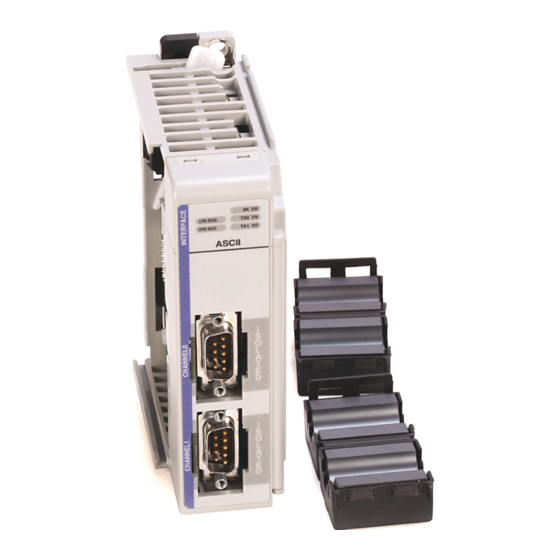
The module provides the communication connections to the ASCII device. Item Description Upper DIN rail latch Lower DIN rail latch Upper tongue-and-groove slots Lower tongue-and-groove slots Channel 0 isolated ASCII connector Channel 1 isolated ASCII connector Stationary bus connector with male pins Rockwell Automation Publication 1769-UM012B-EN-P - January 2014... -
Page 10: Environment And Enclosure
• Industrial Automation Wiring and Grounding Guidelines, Allen-Bradley publication 1770-4.1, for additional installation requirements • NEMA Standards publication 250 and IEC publication 60529, as applicable, for explanations of the degrees of protection provided by different types of enclosure Rockwell Automation Publication 1769-UM012B-EN-P - January 2014... -
Page 11: North American Hazardous Location Approval
Classe I, Division 2. • If this product contains batteries, they • S'assurer que l'environnement est classé non must only be changed in an area known dangereux avant de changer les piles. to be nonhazardous. Rockwell Automation Publication 1769-UM012B-EN-P - January 2014... -
Page 12: European Hazardous Location Approval
• Do not disconnect equipment unless power has been removed or the area is known to be nonhazardous. ATTENTION: This equipment is not resistant to sunlight or other sources of UV radiation. Rockwell Automation Publication 1769-UM012B-EN-P - January 2014... -
Page 13: Install The Module
(2) Over Voltage Category II is the load level section of the electrical distribution system. At this level, transient voltages are controlled and do not exceed the impulse voltage capability of the product’s insulation. (3) Pollution Degree 2 and Over Voltage Category II are International Electrotechnical Commission (IEC) designations. Rockwell Automation Publication 1769-UM012B-EN-P - January 2014... -
Page 14: Assemble The System
ATTENTION: When attaching I/O modules, it is important that the bus connectors are securely locked together to be sure of proper electrical connection. 8. Attach an end-cap terminator (5) to the last module in the system by using the tongue-and-groove slots as before. Rockwell Automation Publication 1769-UM012B-EN-P - January 2014... -
Page 15: Minimum Space
For more than 2 modules: ( number of modules - 1) X 35 mm (1.38 in.) 28.5 Refer to host controller documentationfor this dimension. (1.12) (1.38) (5.197) 122.6±0.2 All dimensions (4.826±0.008) are in mm (inches). Hole spacing tolerance: ±0.4 mm (0.016 in.) Rockwell Automation Publication 1769-UM012B-EN-P - January 2014... -
Page 16: Din Rail Mount
Before mounting the module on a DIN rail, close the DIN rail latches. Press the DIN rail mounting area of the module against the DIN rail. The latches momentarily open and lock into place. Rockwell Automation Publication 1769-UM012B-EN-P - January 2014... -
Page 17: Replace A Module
Additional grounding connections from the module’s mounting tabs or DIN rail (if used) are not required unless the mounting surface cannot be grounded. See Industrial Automation Wiring and Grounding Guidelines, publication 1770-4.1, for additional information. Rockwell Automation Publication 1769-UM012B-EN-P - January 2014... -
Page 18: Connect The D-Sub Connector Pins
Do Not Connect Transmit Data + Transmit/Receive Data + Figure 1 - RS-232 Wiring Diagram - Module to DTE Device (hardware handshaking disabled) 9-pin 25-pin ASCII DTE (1) Connect to the shield of the cable. Rockwell Automation Publication 1769-UM012B-EN-P - January 2014... - Page 19 ASCII DTE 9-pin 25-pin N.C. Figure 3 - RS-422 Wiring Diagram ASCII TXD- RXD- RXD- TXD- RXD+ TXD+ TXD+ RXD+ Figure 4 - RS-485 Wiring Diagram ASCII TRXD- TRXD- TRXD+ TRXD+ Rockwell Automation Publication 1769-UM012B-EN-P - January 2014...
- Page 20 Chapter 1 Compact I/O ASCII Module Notes: Rockwell Automation Publication 1769-UM012B-EN-P - January 2014...
-
Page 21: Configure The 1769-Ascii Module
64203. Configure the 1769-ASCII Follow these steps to add and configure the 1769-ASCII module. Module 1. Right click on the 1769 Compact Bus in your Logix Designer project and choose New Module. Rockwell Automation Publication 1769-UM012B-EN-P - January 2014... - Page 22 The Add-On Profile can be downloaded and installed from https:// download.rockwellautomation.com/esd/ download.aspx?downloadid=addonprofiles RSLogix5000 software, version 16 is the minimum revision compatible with the 1769-ASCII module Add-On-Profile. The module appears in the configuration tree. 5. Right-click on the module and choose Properties. Rockwell Automation Publication 1769-UM012B-EN-P - January 2014...
- Page 23 11. Click Change on the General tab to modify the module definition parameters. The Module Definition box appears. The examples used later in this chapter, has electronic keying disabled but compatible keying is suggested. For mor information, see Electronic Keying on page 105. Rockwell Automation Publication 1769-UM012B-EN-P - January 2014...
-
Page 24: Module Definition Dialog Box
The connection type between the controller writing the configuration and the I/O module is Output. Data Format Integer data transferred between the controller and I/O module and what tags are generated when the configuration is complete. Rockwell Automation Publication 1769-UM012B-EN-P - January 2014... - Page 25 ASCII protocol configuration can be done under Configuration tab. Channels 0 and 1 can have different configuration. Advanced ASCII protocol configuration like Byte Swap Mode can be done under Advanced Configuration tab. Channels 0 and 1 can have different advanced configurations. Rockwell Automation Publication 1769-UM012B-EN-P - January 2014...
- Page 26 • Select a requested packet interval (RPI) • Choose to inhibit or uninhibit the module • Configure the controller so that a loss of connection to this module causes a major fault • View module faults Rockwell Automation Publication 1769-UM012B-EN-P - January 2014...
- Page 27 The configuration in the module is invalid. (This error is commonly caused by the Electronic Key Passed fault.) Electronic Keying Mismatch Electronic Keying is enabled and some part of the keying information differs between the software and the module. Rockwell Automation Publication 1769-UM012B-EN-P - January 2014...
- Page 28 Use Data Bits, Parity, and Stop Bits to configure serial data formats. Data Bits Choose 7 (default) or 8 for the Data Bits. Data Bits appears dimmed Run mode. Parity Choose Odd, Even, or None (default) for the Parity. Parity appears dimmed Run mode. Rockwell Automation Publication 1769-UM012B-EN-P - January 2014...
- Page 29 Termination Delimiter appears dimmed in Run mode. Transmit Data Configure the channel’s termination mode. These are the valid values. • Ignore Delimiter • Exclude Delimiter • Include Delimiter (default) Termination Mode appears dimmed in Run mode. Rockwell Automation Publication 1769-UM012B-EN-P - January 2014...
- Page 30 Chapter 2 Configure the 1769-ASCII Module 1769-ASCII Module Advanced Configuration Dialog Box Use this dialog box to configure advanced parameters, such as receiving and transmitting data. Rockwell Automation Publication 1769-UM012B-EN-P - January 2014...
- Page 31 Pad appears dimmed in Run mode. Transmit Data Byte Swap Mode These are the valid values. • Disabled (default) • 2 – bytes • 4 – bytes Byte Swap Mode appears dimmed in Run mode. Rockwell Automation Publication 1769-UM012B-EN-P - January 2014...
-
Page 32: Controller-Scoped Tags
These are the Module-Defined data types that are used in the following exercises. The 1769-ASCII Add-On Profile displays the data types with a descriptive name. These dialog boxes differ slightly depending on whether you select Alternating or Simultaneous mode. Rockwell Automation Publication 1769-UM012B-EN-P - January 2014... - Page 33 Configure the 1769-ASCII Module Chapter 2 This is an example of Module-Defined data types. Rockwell Automation Publication 1769-UM012B-EN-P - January 2014...
-
Page 34: Connect To Channel 0 Of The Module In Alternating Mode
RS-232 connection between PC with a serial port and the 1769-ASCII module D-sub connector. If your computer does not have an RS-232 port, you can use a USB to RS-232 adapter. Rockwell Automation Publication 1769-UM012B-EN-P - January 2014... -
Page 35: Ladder Logic Example
1769-ASCII module in alternating mode. This is the ladder logic in the Logix Designer program, L35ERM_QuickStart_002_V16.ACD. Main Routine The Main Routine resets the values of input and output lengths. This zeroes the data in and out. Rockwell Automation Publication 1769-UM012B-EN-P - January 2014... - Page 36 Then the new RxID number is moved as the old to set up for new data on the received. Rockwell Automation Publication 1769-UM012B-EN-P - January 2014...
- Page 37 Configure the 1769-ASCII Module Chapter 2 Output Ladder The Output ladder moves the data in the tag. OutData moves it to the output buffer then changes the transaction ID to send the data out. Rockwell Automation Publication 1769-UM012B-EN-P - January 2014...
-
Page 38: Configure The Module Properties
Chapter 2 Configure the 1769-ASCII Module Configure the Module Properties Use the Module Properties dialog box to configure parameters for the module. The following screens illustrate example module settings. 1769-ASCII Module General Dialog Box Module Definition Dialog Box Rockwell Automation Publication 1769-UM012B-EN-P - January 2014... - Page 39 Configure the 1769-ASCII Module Chapter 2 1769-ASCII Module Connection Dialog Box 1769-ASCII Module Configuration Dialog Box Rockwell Automation Publication 1769-UM012B-EN-P - January 2014...
- Page 40 Chapter 2 Configure the 1769-ASCII Module 1769-ASCII Module Advanced Configuration Dialog Box Rockwell Automation Publication 1769-UM012B-EN-P - January 2014...
-
Page 41: Connect To Both Channels Of The Module In Alternating Mode
1769-ASCII module D-sub connector. If your computer does not have an RS-232 port, you can use a USB to RS-232 adapter. To access the Logix Designer programs, see the Knowledgebase Technote # 64203 at https://rockwellautomation.custhelp.com/app/answers/detail/a_id/ 64203. Rockwell Automation Publication 1769-UM012B-EN-P - January 2014... -
Page 42: Ladder Logic Example
This ladder logic example illustrates how to connect to both channels of the module in alternating mode. This is the ladder logic in the Logix Designer program, L35ERM_QuickStart_003_V16.ACD Main Routine The Main Routine Zeros out the InData & OutData array lengths. Rockwell Automation Publication 1769-UM012B-EN-P - January 2014... - Page 43 Chapter 2 Input Channel0 The Input Channel0 does the following tasks: • On first scan, stores current value of Rx0 Transaction ID (channel 0) as ‘most recent’ . • Monitors the Rx0 Transaction ID. Rockwell Automation Publication 1769-UM012B-EN-P - January 2014...
- Page 44 • Copies data from the module's Input Tags to a STRING tag (InData1) if CNI = 1. • Indicates to the MainRoutine that new data has arrived. Saves this value of Rx Transaction ID, so you can detect the next change. Rockwell Automation Publication 1769-UM012B-EN-P - January 2014...
- Page 45 • Copies the data from the STRING (OutData0) to the module's output tag. • If CN0 = 0, manually triggers the Tx Transaction ID in the 1769-ASCII Module's output tag. This tells it that you have some data for it to send. Rockwell Automation Publication 1769-UM012B-EN-P - January 2014...
- Page 46 • Copies data from the STRING (OutData1) to the module's output tag. • If CN0 = 1, manually triggers the Tx Transaction ID in the module's output tag. This tells it that you have some data for it to send. Rockwell Automation Publication 1769-UM012B-EN-P - January 2014...
- Page 47 Configure the 1769-ASCII Module Chapter 2 1769-ASCII Module General Dialog Box 1769-ASCII Module Connection Dialog Box Rockwell Automation Publication 1769-UM012B-EN-P - January 2014...
- Page 48 Chapter 2 Configure the 1769-ASCII Module 1769-ASCII Module Configuration Dialog Box 1769-ASCII Module Advanced Configuration Dialog Box Rockwell Automation Publication 1769-UM012B-EN-P - January 2014...
-
Page 49: Mode
If your computer does not have an RS-232 port, you can use a USB to RS-232 adapter. For more detailed information about the Alternate and Simultaneous modes, see I/O Memory Mapping on page To access the Logix Designer programs, see the Knowledgebase Technote # 64203 at https://rockwellautomation.custhelp.com/app/answers/detail/a_id/ 64203. Rockwell Automation Publication 1769-UM012B-EN-P - January 2014... -
Page 50: Ladder Logic Example
This is the ladder logic in the Logix Designer project, L35ERM_QuickStart_004_V16.ACD. This example program illustrates connecting the cable from your computer to both channels of the 1769-ASCII module. Main Routine The Main Routine zeros out the InData & OutData arrays. Rockwell Automation Publication 1769-UM012B-EN-P - January 2014... - Page 51 The Input Channel0 does the following tasks: • Stores the current value, on the first scan, as the current value of Rx0 Transaction ID (channel 0) as most recent. • Monitors the Rx0 Transaction ID Rockwell Automation Publication 1769-UM012B-EN-P - January 2014...
- Page 52 • Copies the data from the module's Input Tags to a STRING tag (InData1). • Indicates to the MainRoutine that new data has arrived. • Saves the value of Rx Transaction ID, so you can detect next change. Rockwell Automation Publication 1769-UM012B-EN-P - January 2014...
- Page 53 • Copies the Length of the number of bytes of the OutputData0 array. • Triggers the Tx Transaction ID in the module's output tag. This tells it that you have some data for it to send. Rockwell Automation Publication 1769-UM012B-EN-P - January 2014...
- Page 54 • Copies the Length of the number of bytes of the OutputData1 array. • Triggers the Tx Transaction ID in the module's output tag. This tells it that you have some data for it to send. Rockwell Automation Publication 1769-UM012B-EN-P - January 2014...
- Page 55 When the I/O module properties appear, enter the following information: a name, the appropriate slot number, specify a Comm Format of Data_INT, and enter the following values: Data Type: AB:1769_ASCII:C:0 Data Type: AB:1769_ASCII_80Bytes_80Bytes:I:0 Rockwell Automation Publication 1769-UM012B-EN-P - January 2014...
- Page 56 Chapter 2 Configure the 1769-ASCII Module Data Type: AB:1769_ASCII_80Bytes_80Bytes:O:0 1769-ASCII Module General Dialog Box Rockwell Automation Publication 1769-UM012B-EN-P - January 2014...
- Page 57 Configure the 1769-ASCII Module Chapter 2 1769-ASCII Module Connection Dialog Box 1769-ASCII Module Configuration Dialog Box Rockwell Automation Publication 1769-UM012B-EN-P - January 2014...
- Page 58 Chapter 2 Configure the 1769-ASCII Module 1769-ASCII Module Advanced Configuration Dialog Box Rockwell Automation Publication 1769-UM012B-EN-P - January 2014...
-
Page 59: Configure The Module For Use With A Micrologix Controller
4. Type a name. 5. Type a Description. 6. Review the Module Definition area and make sure the information is correct. 7. Click Change on the General tab to modify the module definition parameters. Rockwell Automation Publication 1769-UM012B-EN-P - January 2014... - Page 60 Mode, the sum of Channel 1 and Channel 2 for Receive and Transmit characters cannot exceed 200 bytes. 9. Module's RPI can be configured through Connection tab. RPI can be configured in multiples of 0.5. Rockwell Automation Publication 1769-UM012B-EN-P - January 2014...
- Page 61 10. ASCII protocol configuration can be done under Configuration tab. Channels 0 and 1 can have different configuration. Advanced ASCII protocol configuration like Byte Swap Mode can be done under Advanced Configuration tab. Channels 0 and 1 can have different advanced configurations. Rockwell Automation Publication 1769-UM012B-EN-P - January 2014...
-
Page 62: Programming Example: Micrologix 1500 Controller
5. From the list, select Other: Requires I/O Card Type ID. 6. When the I/O module properties appear, enter the following information. Assembly Instance Size Input Output Configuration 7. Click OK. 8. Click Adv. Config. Rockwell Automation Publication 1769-UM012B-EN-P - January 2014... - Page 63 Configure the 1769-ASCII Module Chapter 2 9. From the Generic Extra Data Config tab, enter your application data by referring to the Configuration File. 10. Click OK. 11. Create your program by using these tags. Rockwell Automation Publication 1769-UM012B-EN-P - January 2014...
- Page 64 In this example, the following tags were used. Name Type File Ref Value InData String ST11:0 Empty OutData String ST11:1 Enter your string NewInput Bool B3:0 NewRx N7:1 OldRx N7:0 Intermediate Storage N7:2 • Input Rockwell Automation Publication 1769-UM012B-EN-P - January 2014...
- Page 65 Configure the 1769-ASCII Module Chapter 2 Rockwell Automation Publication 1769-UM012B-EN-P - January 2014...
- Page 66 Chapter 2 Configure the 1769-ASCII Module • Output Rockwell Automation Publication 1769-UM012B-EN-P - January 2014...
- Page 67 Configure the 1769-ASCII Module Chapter 2 Rockwell Automation Publication 1769-UM012B-EN-P - January 2014...
- Page 68 16. Configure HyperTerminal so that the configuration matches the ASCII device for communication rate and framing. 17. Turn off flow control. 18. In the HyperTerminal application, type in a value. 19. Press enter. Rockwell Automation Publication 1769-UM012B-EN-P - January 2014...
- Page 69 Indata (ST11:0). New data triggers the output from another file Outdata (ST11:1). The data back on the terminal is not the same as the data sent from the terminal. You must put in a data string in Outdata (ST11:1) before running the program. Rockwell Automation Publication 1769-UM012B-EN-P - January 2014...
- Page 70 Chapter 2 Configure the 1769-ASCII Module Notes: Rockwell Automation Publication 1769-UM012B-EN-P - January 2014...
-
Page 71: I/O Memory Mapping
Run mode, the module follows whatever rules are configured then. In your program, use the Rx Transaction ID value in the input tag on the first scan to compare for new data. Rockwell Automation Publication 1769-UM012B-EN-P - January 2014... -
Page 72: Alternate Mode (One Channel At A Time) Output File
Character 198 Local:S:O.TxData (1) Reserved is expected in 1st instance word 0. (2) Tag name format is `Local:S:O’ where 'S' represents slot number. (3) Used for handshaking mode. (4) Used for handshaking mode. Rockwell Automation Publication 1769-UM012B-EN-P - January 2014... -
Page 73: Alternate Mode (One Channel At A Time) Input File
Character … Local:S:I.RxData Character 197 Character 196 Local:S:I.RxData Character 199 Character 198 Local:S:I.RxData (1) Tag name format is `Local:S:I’ where `S’ represents slot number. (2) Reserved is expected in 1st instance word 0. Rockwell Automation Publication 1769-UM012B-EN-P - January 2014... -
Page 74: Simultaneous Mode
(2) X is calculated based on the size of Channel 0 data as specified in the input file. Both channels cannot contain 200 characters as the total configuration file size can be only 108 words. (3) Y is the connection size minus 1, with a maximum value of 107 for a buffer size of 108. Rockwell Automation Publication 1769-UM012B-EN-P - January 2014... -
Page 75: Simultaneous Mode (Two Channels) Output File
(3) X is calculated based on the size of Channel 0 data as specified in the configuration file. Both channels cannot contain 200 characters as the total configuration size can be only 108 words. (4) Used for handshaking. (5) Y is equal to the connection size minus 1, with a maximum value of 107 for a buffer size of 108. Rockwell Automation Publication 1769-UM012B-EN-P - January 2014... -
Page 76: Status Descriptions
Transmit buffer overflow. Some output data has been lost. ChxTxDataSent Transmit sent. Indicates that the 1769-ASCII module has sent the data indicated by the Tx Transaction ID and can accept more transmit data. Rockwell Automation Publication 1769-UM012B-EN-P - January 2014... -
Page 77: Configuration File
0 = ignore, 1 = exclude, 2 = include end delimiter Ch0TxEndDelimiter Transmit End Delimiter 0…127/255 0…0x7f (0…127) for 7-bit data 0…0xff (0…255) for 8-bit data Ch0TxByteSwapMode Transmit Swap Mode 0…2 0 = disabled, 1 = 16-bit, 2 = 32-bit Rockwell Automation Publication 1769-UM012B-EN-P - January 2014... - Page 78 0 = disabled, 1 = 16-bit, 2 = 32-bit (1) To enter values 128…255, use this conversion formula: Desired Decimal Value - 256 = Entered Decimal Value. For example, for an ASCII character value of 128, 128 - 256 = -128. Rockwell Automation Publication 1769-UM012B-EN-P - January 2014...
-
Page 79: Configuration File Parameter Operation
• If the Start Delimiter is not used, the module receives and stores any valid characters received after the completion of the previous message. • If the Stop Delimiter is not used, the module collects data up to the Max Receive Characters parameter value. Rockwell Automation Publication 1769-UM012B-EN-P - January 2014... -
Page 80: Set Up The Receive Delimiters
(if you selected the time-out option). The Receive Data, Transmit Data Swap, Handshake mode, MSG Timeout, and Pad Character are all handled per channel on the Advance Configuration tab in the Add-On Profile. Rockwell Automation Publication 1769-UM012B-EN-P - January 2014... -
Page 81: Set Up The Transmit Delimiter
If the total size of the two channels is greater than 200 characters, the Alternate mode must be used. Rockwell Automation Publication 1769-UM012B-EN-P - January 2014... -
Page 82: Set Up The Transmit Character Buffer Length
This length is equal to the one specified in the Receive Character Length parameter. You specify the Pad mode character to add to the received serial data, which is 0…127 in 7-bit mode and 0…255 in 8-bit mode. Rockwell Automation Publication 1769-UM012B-EN-P - January 2014... -
Page 83: Byte Swap Mode
Number of Receive Characters parameter until the module receives a delimiter. The 1769-ASCII module also sends the overflow error until a delimiter is received. This process continues indefinitely until the ASCII device transmits the specified delimiter. Rockwell Automation Publication 1769-UM012B-EN-P - January 2014... -
Page 84: Receive Timeout
The third and fourth bytes are length indicators. The ensuing bytes are the data that you wish to send to the 1769-ASCII module. If you use the Byte-Swap mode, all transaction and receive strings must be IMPORTANT in multiples of 2 bytes. Rockwell Automation Publication 1769-UM012B-EN-P - January 2014... -
Page 85: How To Receive Serial Data From The 1769-Ascii Module
Value Meaning Set New Data Status bit and wait for application to increment record number Automatically increment the record number and show the new data when an end event is received Rockwell Automation Publication 1769-UM012B-EN-P - January 2014... - Page 86 Chapter 3 I/O Memory Mapping Notes: Rockwell Automation Publication 1769-UM012B-EN-P - January 2014...
-
Page 87: Configure The 1769-Ascii Module As A Generic Module
4. When the I/O module properties appear, enter the following information: a name, the appropriate slot number, specify a Comm Format of Data_INT, and enter the following values: Assembly Instance Size Input Output Configuration 5. Press OK. Rockwell Automation Publication 1769-UM012B-EN-P - January 2014... - Page 88 Use an Rx End delimiter, but exclude it from the input buffer Use a Carriage Return as the Rx End delimiter Produce data when available Max Tx Characters This is a controller-scoped configuration tag. Rockwell Automation Publication 1769-UM012B-EN-P - January 2014...
- Page 89 STRING A two-character string of $R$L NewRx NumInts OldRx LenIn Alias to ASCII module’s I:Data[7] LenOut Alias to ASCII module’s O:Data[7] TxOut0 Alias to ASCII module’s O:Data[0] TxRxIn0 Alias to ASCII module’s I:Data[0] Rockwell Automation Publication 1769-UM012B-EN-P - January 2014...
- Page 90 Appendix A Configure the 1769-ASCII Module as a Generic Module 8. Create two ladder routines in the MainProgram, named Input and Output. This is the main routine. Rockwell Automation Publication 1769-UM012B-EN-P - January 2014...
- Page 91 Configure the 1769-ASCII Module as a Generic Module Appendix A 9. Enter rungs into the three routines as follows: • input Rockwell Automation Publication 1769-UM012B-EN-P - January 2014...
- Page 92 Appendix A Configure the 1769-ASCII Module as a Generic Module • output Rockwell Automation Publication 1769-UM012B-EN-P - January 2014...
- Page 93 Type some text into HyperTerminal. When you press enter, the ASCII module returns the same line of text back to your screen. For a detailed example, see the 1769-ASCII module example in RSLogix 5000 software, version 15, called Example_for_1769-_ASCII_Module.ACD at \RSLogix 5000\Projects\Samples\ENU\v15\Rockwell Automation. Rockwell Automation Publication 1769-UM012B-EN-P - January 2014...
- Page 94 Appendix A Configure the 1769-ASCII Module as a Generic Module Notes: Rockwell Automation Publication 1769-UM012B-EN-P - January 2014...
-
Page 95: Status Indicators
Bus master is detected, configuration is accepted, and in program mode Blinking red Module configuration from the bus master was not valid Tx0, Tx1 Blinking green Transmitting data on that serial port Rx0, Rx1 Blinking green Receiving data on that serial port Rockwell Automation Publication 1769-UM012B-EN-P - January 2014... - Page 96 Appendix B Status Indicators Notes: Rockwell Automation Publication 1769-UM012B-EN-P - January 2014...
-
Page 97: Error Codes
The maximum input array size is too large. exceeded In alternating mode, channel 0 and channel 1 must have less than 496 receive bytes. In simultaneous mode, channel 0 and channel 1 must have less than 496 receive bytes collectively. Rockwell Automation Publication 1769-UM012B-EN-P - January 2014... - Page 98 44F-47F Undefined channel 0 error An undefined error has occurred.frogProduct group / Western Reserve Controls what should be done if this error is received? Is the unit faulty and should it be replaced? Rockwell Automation Publication 1769-UM012B-EN-P - January 2014...
- Page 99 Invalid transmit record end mode The transmit record end mode specified is invalid. Invalid transmit end delimiter The transmit end delimiter specified is invalid. Invalid transmit swap mode The transmit swap mode specified is invalid. Rockwell Automation Publication 1769-UM012B-EN-P - January 2014...
-
Page 100: Logix Designer Example Report
To generate a report in Logix Designer, follow these instructions. Report 1. From the File menu, choose Generate Report. 2. Select what you want to see in the report. 3. Print to a PDF file or another format. Rockwell Automation Publication 1769-UM012B-EN-P - January 2014... - Page 101 Error Codes Appendix C Rockwell Automation Publication 1769-UM012B-EN-P - January 2014...
-
Page 102: Rslogix 500 Error Report Example
Choosing Fault provides the status window with error code 179h. 4. In the project space, choose Controller>Function Files>IOS tab. This IOS tab corresponds with the module number in the rack and returns the error number. The RSLogix 500 software explains the error. Rockwell Automation Publication 1769-UM012B-EN-P - January 2014... -
Page 103: Ascii Conversion Tables
Control S, DC3 0101100 0010100 Control T, DC4 0101101 0010101 Control U, NAK 0101110 0010110 Control V, SYN 0101111 0010111 Control W, EB 0110000 0011000 Control X, CAN 0110001 0110010 1010101 0110011 1010110 0110100 1010111 Rockwell Automation Publication 1769-UM012B-EN-P - January 2014... - Page 104 11010111 1001001 1101100 1001010 1101101 1001011 1101110 1001100 1101111 1001101 1110000 1001110 1110001 1001111 1110010 1010000 1110011 1010001 1110100 1010010 1110101 1010011 1110110 1010100 1110111 1111000 1111100 1111001 1111101 1111010 1111110 1111011 1111111 Rockwell Automation Publication 1769-UM012B-EN-P - January 2014...
-
Page 105: Using Electronic Keying
Table 15 - Keying Attributes Attribute Description Vendor The manufacturer of the module, for example, Rockwell Automation/Allen-Bradley. Product Type The general type of the module, for example, communication adapter, AC drive, or digital I/O. Product Code The specific type of module, generally represented by its catalog number, for example, 1756-IB16I. -
Page 106: Exact Match
Use Exact Match keying when you need the system to verify that the module revisions in use are exactly as specified in the project, such as for use in highly- regulated industries. Exact Match keying is also necessary to enable Automatic Rockwell Automation Publication 1769-UM012B-EN-P - January 2014... -
Page 107: Compatible Keying
Major Revision. In some cases, the selection makes it possible to use a replacement that is a different catalog number than the original. For example, you can replace a Rockwell Automation Publication 1769-UM012B-EN-P - January 2014... - Page 108 Major Revision = 3 Minor Revision = 3 Communication is prevented. Physical Module Vendor = Allen-Bradley Product Type = Digital Input Module Catalog Number = 1756-IB16D Major Revision = 3 Minor Revision = 2 Rockwell Automation Publication 1769-UM012B-EN-P - January 2014...
-
Page 109: Disabled Keying
We generally do not recommend using Disabled Keying. ATTENTION: Be extremely cautious when using Disabled Keying; if used incorrectly, this option can lead to personal injury or death, property damage, or economic loss. Rockwell Automation Publication 1769-UM012B-EN-P - January 2014... - Page 110 Major Revision = 3 Minor Revision = 1 Communication is prevented. Physical Module Vendor = Allen-Bradley Product Type = Analog Input Module Catalog Number = 1756-IF16 Major Revision = 3 Minor Revision = 2 Rockwell Automation Publication 1769-UM012B-EN-P - January 2014...
- Page 111 Major Revision = 3 Minor Revision = 2 Changing electronic keying selections online may cause the I/O IMPORTANT communication connection to the module to be disrupted and may result in a loss of data. Rockwell Automation Publication 1769-UM012B-EN-P - January 2014...
- Page 112 Appendix E Using Electronic Keying Notes: Rockwell Automation Publication 1769-UM012B-EN-P - January 2014...
-
Page 113: History Of Changes
• Added Electronic Keying appendix. • Updated Additional Resources. • Moved the generic module content to an appendix. • Updated Technical Support links, website addresses, and phone numbers. • Added the History of Changes appendix. Rockwell Automation Publication 1769-UM012B-EN-P - January 2014... - Page 114 Appendix F History of Changes Notes: Rockwell Automation Publication 1769-UM012B-EN-P - January 2014...
-
Page 115: Index
73 Compact I/O ASCII Module 9 simultaneous mode 74 CompactLogix 21 input ladder 36 compatible keying 107 IP54 protection 12 configuration file 77 parameter operation 79 connection 24 connector pins 18 controller-scoped 32 Rockwell Automation Publication 1769-UM012B-EN-P - January 2014... - Page 116 29 data padding 82 ventilation 15 delimiter mode 79 delimiters 80 timeout 84 reports 100 writing example 102 serial output data 85 resources 8 revision 24 RPI 25 RS-232 7 wiring diagram 18 Rockwell Automation Publication 1769-UM012B-EN-P - January 2014...
- Page 118 New Product Satisfaction Return Rockwell Automation tests all of its products to help ensure that they are fully operational when shipped from the manufacturing facility. However, if your product is not functioning and needs to be returned, follow these procedures.
Need help?
Do you have a question about the Allen-Bradley 1769-ASCII and is the answer not in the manual?
Questions and answers