AMX Endeleo TVM-1600 Quick Start Manual
Endeleo managed tv distribution hub
Hide thumbs
Also See for Endeleo TVM-1600:
- Quick start manual (2 pages) ,
- User manual (56 pages) ,
- Operation/reference manual (66 pages)
Table of Contents
Advertisement
Quick Links
Download this manual
See also:
User Manual
Overview
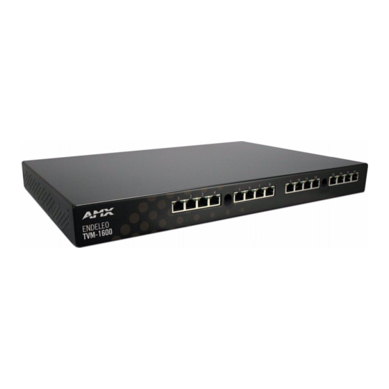
The TVM-1600 Managed TV Distribution Hub is the central node of the system that
converts the multi-channel RF input to user selectable video channels for distribution
using the standard building infrastructure (FIG. 1).
UTP Ports 1-16 (to TVM-RX03 Receivers)
RF Input (from cable provider)
RF Output (to another TVM-1600)
Serial Control (RS-232) Port
IR Port (to TVM-IR04 IR Breakout Box)
RJ45 Network Connector
FIG. 1
TVM-1600
The input to the TVM-1600 is via an industry standard RF feed and the output is
presented as an RJ45 socket for connection to the Cat5, 5e or 6 twisted pair cable.
The selected video channel is then transmitted via the UTP cable to a TVM-RX03
Managed TV receiver which can be up to 3000' (1000m) away from the TVM-1600.
Multiple hubs can be chained together providing support and control to hundreds or
even thousands of users/displays.
Each hub has an Ethernet network port to provide connectivity to the central
management system or can be controlled by the onboard web pages.
Product Specifications
TVM-1600 Specifications
Models Available:
• US version (FG-TVM-1600): Pre-configured to work with
standard US NTSC frequencies.
• International version (FG-TVM-1600-PSC):
Pre-configured to work with standard PAL and SECAM
frequencies.
Power:
Operating Voltage: 100-240 VAC, 50-60 Hz
3-pin IEC male connector
• FG-TVM-1600:110v AC, 60W
• FG-TVM-1600-PSC: 240v AC, 60W
Front Panel
• RJ45 Connectors: 16 RJ45 ports to connect TVM-RX03
units.
Connectors:
• IR Sensors: 2 IR sensors
Rear Panel
• RF Input: Coax connector (RF feed from Cable or
Satellite provider)
Connectors:
• RF Output: Coax connector allows you to connect to
another TVM-1600, for cascading.
• Serial Connector: RS-232 control port.
• IR Port: Connects to up to 4 TVM-IR04 IR Breakout
boxes (optional).
• RJ45 Network Connector:
• Power Switch/Outlet
RF Input:
• Levels: 80-120 dBuV 75ohm, max 6dB variation between
channels
• Mechanical: F connector, female
RF Output:
• Insertion Loss: 3.5 dB
• Mechanical: F Connector, female
Channel Coverage:
NTSC:
• Channels: A2 to A69 (55.25 - 801.25 MHz)
• Standards: NTSC M
PAL/SECAM:
• Channels: E2 to E69 (48.25 - 855.25 MHz)
• Standards: PAL B/G, D/K, I, SECAM L/L
On Screen Display:
• 28 characters and 11 rows that are fully configurable.
• Auto display of selected channel name and channel
number.
Operating
• Operating Temperature: 0° to 50° C (32° to 122° F)
Environment:
• Storage Temperature: -20° to 50° C (-4° to 122° F)
Dimensions (HWD):
• 1 11/16" x 17 1/4" x 12 1/4" (43 mm x 438 mm x 312 mm)
• 1U rack space
Weight:
9.0 lbs. (4.0 kg)
TVM-1600
IR Sensor
Power switch
Power connector
Endeleo Managed TV Distribution Hub
TVM-1600 Specifications (Cont.)
Certifications:
Included Accessories:
Other AMX Equipment: • TVM-RX03: Managed TV Receiver (FG-TVM-RX03)
(front)
(rear)
Connecting TVM-RX03 Managed TV Receivers
The RJ45 UTP connectors on the front panel of the TVM-1600 (FIG. 1) are used to
connect up to 16 TVM-RX03 Managed TV Receiver units.
Note: THIS IS NOT AN ETHERNET CONNECTION - the connection should NOT go
through network equipment such as hubs, routers or switches.
RJ45 UTP Connectors
The 16 UTP Ports on the front of the TVM-1600 are standard RJ45 connectors.
TVM-RX03 receivers can be connected to them via Cat5, Cat5e or Cat 6 cabling.
All 8 pins must be terminated on all connections.
FIG. 2
RJ45 Connectors
RJ45 Pinouts
Pin No.
1
2
3
4
5
6
7
8
Each UTP Port on the front of the TVM-1600 connects to one TVM-RX03 receiver, and
each TVM-RX03 connects in turn to one display device. The display device will display
the channel set on the TVM-RX03 to which it is connected.
FIG. 3 provides a basic system diagram showing the first 4 UTP Ports on the
TVM-1600 connected to TVM-RX03 receivers, and display devices:
TVM-1600
CAT 5
RX03
RX03
Display
Display
FIG. 3
UTP Connections (using UTP outputs 1-4 only)
Quick Start Guide
CE, UL, FCC part 15 Class A
• IEC Power Cord
• 6' Ethernet Crossover Cable
• 6' Coax Cable
• RS03 Endeleo Serial Transmit Cable (Straight Thru)
• TVM-RX03A: Managed TV Receiver with Accessories
(FG-TVM-RX03A)
• RS01: RS-232 Serial Transmit Cable (FG-RS01)
• IR01: IR Emitter Module (FG-IR01)
• IR03: External IR Receiver Module (FG-IR03)
• TVM-IR04: Managed TV IR Breakout Box
(FG-TVM-IR04)
• TVM-RC02: Managed TV IR Remote Control
(FG-TVM-RC02)
• TVM-UD01: Managed TV USB A/V Adapter for PC
(FG-TVM-UD01)
• TVM-SW01: Managed TV Enterprise Software, Single
User (FG-TVM-SW01)
• TVM-SW01ENT: Managed TV Enterprise Software,
Enterprise Site License (FG-TVM-SW01ENT)
Function
Balanced video +
Balanced video -
Data output
Balanced audio +
Balanced audio -
Data input
Receiver power +
Receiver power return
CAT 5
CAT 5
CAT 5
RX03
RX03
Display
Display
Advertisement
Table of Contents

Subscribe to Our Youtube Channel
Related Manuals for AMX Endeleo TVM-1600


Summary of Contents for AMX Endeleo TVM-1600
-
Page 1: Product Specifications
FIG. 1 TVM-1600 The input to the TVM-1600 is via an industry standard RF feed and the output is presented as an RJ45 socket for connection to the Cat5, 5e or 6 twisted pair cable. The selected video channel is then transmitted via the UTP cable to a TVM-RX03 Managed TV receiver which can be up to 3000’... -
Page 2: Network Configuration
©2008 AMX. All rights reserved. AMX and the AMX logo are registered trademarks of AMX. AMX reserves the right to alter specifications without notice at any time. 3000 RESEARCH DRIVE, RICHARDSON, TX 75082 • 800.222.0193 • fax 469.624.7153 • technical support 800.932.6993 • www.amx.com Define TV System Type: •...
Need help?
Do you have a question about the Endeleo TVM-1600 and is the answer not in the manual?
Questions and answers