Table of Contents
Advertisement
Quick Links
Advertisement
Table of Contents

Subscribe to Our Youtube Channel
Related Manuals for TSC EZS TDM-30


Summary of Contents for TSC EZS TDM-30
- Page 1 TDM-30 Direct Thermal Portable Printer SERVICE MANUAL...
-
Page 2: Table Of Contents
Contents 1. FUNDAMENTAL OF THE SYSTEM ........2 1.1 Overview ......................2 2. ELECTRONICS ..........3 2.1 Summary of Board Connectors ..............3 3. MECHANISM ..........7 3.1 Replacing the Printer Top Cover (with Keys Control Board) ......7 3.2 Replacing the Linerless Platen Roller Assembly (Option) ......8 3.3 Replacing the Platen Roller ................ -
Page 3: Fundamental Of The System
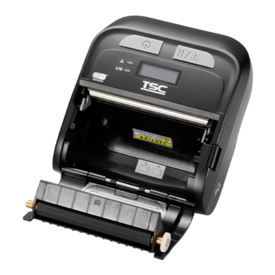
1. FUNDAMENTAL OF THE SYSTEM 1.1 Overview Front View For LED version Power on/off button Feed/stop button LED indicators Media cover Media cover window Media cover release button... - Page 4 For LCD version Power on/off button Feed/stop button LED indicators & LCD screen Media cover Media cover window Media cover release button...
- Page 5 Interior View Tear edge Print head Platen roller Black mark sensor...
- Page 6 Rear View Li-ion Battery Battery open clasp Interface cover Power jack USB interface...
-
Page 7: Electronics
2. ELECTRONICS 2.1 Summary of Board Connectors Main board top Connector Description 12V DC IN Micro USB Connector LED/LCD and Key Board Connector Download F/W Connector Description 3.3V MCI0_DA0 MCI0_DA1 MCI0_DA2 MCI0_DA3 MCI0_CK MCI0_CDA No Connection... - Page 8 TPH Connector Stepping Motor Connector Description AOUT1 AOUT2 BOUT2 BOUT1 WiFi Module Connector Description RESET 3.3V MISO MOSI Interrupt WB GPIO Black Mark Sensor Description 3.3V BM_E BM_R 3.3V Gap Sensor Description 3.3V BM_E BM_R 3.3V Head Open Sensor Description HEAD...
- Page 9 Cradle Connector Description Charge Status ISET RTC Battery Description VDDBU...
- Page 10 Main board bottom Connector Description Battery connector Positive Electrode Description Battery connector Negative Electrode Description Smart BAT SCL Smart BAT SDA...
-
Page 11: Mechanism
3. MECHANISM 3.1 Replacing the Printer Top Cover (with Keys Control Board) 1. Remove four screws from the back of the printer as indicated. Screws 2. Remove the cable on cable connector and take out the printer top cover (with keys control board). -
Page 12: Replacing The Linerless Platen Roller Assembly (Option)
3.2 Replacing the Linerless Platen Roller Assembly (Option) 1. Open the printer cover by pressing the media release button. 2. Remove one screw on the linerless platen roller assembly as indicated. Screw 3. Pull out and remove the linerless platen roller assembly as indicated. - Page 13 4. Remove/Replace the linerless platen roller assembly. Linerless Platen Roller Assembly 5. Reassemble the parts in the reverse procedures.
-
Page 14: Replacing The Platen Roller
3.3 Replacing the Platen Roller 1. Open the media cover by pressing the media cover release button. 2. Remove one screw on the platen roller assembly as indicated. Screw 3. Pull out and remove the platen roller assembly as indicated. - Page 15 4. Remove/Replace the platen roller assembly. Platen Roller Assembly 5. Reassemble the parts in the reverse procedures.
-
Page 16: Replacing The Keys Control Board
3.4 Replacing the Keys Control Board 1. Refer to section 3.1 to remove the printer top cover (with keys control board). 2. Remove four screws on the keys control board as indicated. Screws 3. Remove/Replace the keys control board. Keys Control Board 4. -
Page 17: Replacing The Main Board Assembly
3.5 Replacing the Main Board Assembly 1. Refer to section 3.1 to remove the printer top cover (with keys control board). 2. Remove three screws on interior mechanism and disconnect all the connectors on the main board assembly as indicated. Screws 3. -
Page 18: Replacing The Bluetooth Module (Option)
3.6 Replacing the Bluetooth Module (Option) 1. Refer to section 3.1 to remove the Printer Top Cover (with Keys Control Board) and the Main Board Assembly. 2. Turn to the rear side of main board assembly. The Bluetooth module was embedded in main board as indicated. -
Page 19: Replacing The Gear Assembly & Stepping Motor
3.7 Replacing the Gear Assembly & Stepping Motor 1. Refer to section 3.1 to remove the Printer Top Cover (with Keys Control Board). 2. Remove three screws on interior mechanism and disconnect all the connectors on the main board assembly as indicated. Screws 3. - Page 20 4. Remove the gears and release two screws as indicated. Screws 5. Remove/Replace the stepping motor assembly. Stepping Motor Assembly 6. Reassemble the parts in the reverse procedures.
-
Page 21: Replacing The Print Head Assembly
3.8 Replacing the Print Head Assembly 1. Refer to section 3.1 to remove the Printer Top Cover (with Keys Control Board), Gear Assembly, and Stepping Motor. 2. Turn the print mechanism to left side than remove one screw fixed on print head fixed bar. - Page 22 4. Remove/Replace the print head assembly along the path as indicated. Print Head Assembly 5. Reassemble the parts in the reverse procedures.
-
Page 23: Replacing The Black Mark Sensor Assembly
3.9 Replacing the Black Mark Sensor Assembly 1. Refer to section 3.1 to remove the Printer Top Cover (with Keys Control Board). 2. Remove three screws on interior mechanism and disconnect all the connectors on the main board assembly as indicated. Screws 3. -
Page 24: Replacing The Open Sensor
3.10 Replacing the Open Sensor 1. Refer to section 3.1 to remove the Printer Top Cover (with Keys Control Board). 2. Remove three screws on interior mechanism and disconnect all the connectors on the main board assembly as indicated. Screws 3. -
Page 25: Troubleshooting
TROUBLESHOOTING 4.1 Common Problems The following guide lists the most common problems that may be encountered when operating this bar code printer. If the printer still does not function after all suggested solutions have been invoked, please contact the Customer Service Department of your purchased reseller or distributor for assistance. -
Page 26: Maintenance
Maintenance This session presents the clean tools and methods to maintain your printer. 1. Please use one of following material to clean the printer. Cotton swab Lint-free cloth Vacuum / Blower brush 100% ethanol 2. The cleaning process is described as following, Printer Part Method Interval... -
Page 27: Revise History
Revise History Date Content Editor... - Page 28 9F., No.95, Minquan Rd., Xindian Dist., No.35, Sec. 2, Ligong 1st Rd., Wujie Township, New Taipei City 23141, Taiwan (R.O.C.) Yilan County 26841, Taiwan (R.O.C.) TEL: +886-2-2218-6789 TEL: +886-3-990-6677 FAX: +886-2-2218-5678 FAX: +886-3-990-5577 Web site: www.tscprinters.com E-mail: printer_sales@tscprinters.com TSC Auto ID Technology Co., Ltd. tech_support@tscprinters.com...
Need help?
Do you have a question about the EZS TDM-30 and is the answer not in the manual?
Questions and answers