ABB Terra DC Wallbox Installation Manual
Hide thumbs
Also See for Terra DC Wallbox:
- Installation manual (44 pages) ,
- User's operation manual (20 pages) ,
- Quick start manual (2 pages)
Table of Contents
Advertisement
Quick Links
Advertisement
Table of Contents

Related Manuals for ABB Terra DC Wallbox


Summary of Contents for ABB Terra DC Wallbox
- Page 1 — MA NUAL : NO RTH A MERI CA Terra DC Wallbox Installation Manual...
- Page 2 This document contains information about one or more ABB products and may include a description of or a reference to one or more standards that may be generally relevant to the ABB products. The presence of any such description of a standard or reference to a standard is not a representation that all of the ABB products referenced in this document support all of the features of the described or referenced standard.
-
Page 3: Table Of Contents
3.3.2 Short circuit current rating ......................15 Spacing Requirements ..........................15 3.4.1 Required space for installing and maintaining the Terra DC Wallbox ........15 3.4.2 Ventilation and airflow of the Terra DC Wallbox ................ 15 Cable reach ..............................16 Different alignment possibilities ......................... 17 4 Site construction ............................ - Page 4 9 Contact information ............................. 38 10 Appendix A – Mounting points ........................39 10.1 Terra DC Wallbox Charger wall mounting ....................39 11 Appendix B - Disposal instruction ......................... 40 11.1 Directive on Waste Electrical and Electronic Equipment (WEEE – 2012/19/EU) ........40...
- Page 5 Grid provider Company responsible for the transportation and distribution of electricity. Human Machine Interface; the display/screen on the charger. ABB Network Operating Centre; remotely checks the correct functioning of the charger. Owner The legal owner of the charger. OCPP Open Charge Point Protocol. Open standard for communication with charge stations.
-
Page 6: Introduction
This guide provides an overview for the installation of the Terra DC Wallbox. The Terra DC Wallbox charging station is an easy to install DC fast charger for electric vehicles. Fast chargers are electrical installations with high electric currents. Therefore, the installation must be planned carefully, and must be done by certified personnel only (according to local standards). -
Page 7: Signs
TER R A DC WAL LB OX Signs The following signs are used on the equipment and in this manual: DANGER Hazardous voltage Identifies a hazard that could result in severe injury or death through electrocution. WARNING Various Identifies a hazard that could result in severe injury or death. WARNING Rotating parts Identifies a hazard that could result in injury due to the presence of... -
Page 8: Tilting And Handling
ABB’s warranty policy. Neither ABB nor its affiliates shall be liable to the purchaser of this product or third parties for damages, losses, costs or expenses incurred by purchaser or third parties as a result of: an accident, misuse or abuse of this product or unauthorized modifications, repairs or alterations to this product, or failure to strictly comply with ABB’s... -
Page 9: Installation Safety
Instruct and warn people about the potentially harmful high voltages. 5. The installation and maintenance personnel must supply their own lighting equipment because the Terra DC Wallbox has no lights inside the cabinet. 6. Always connect the Protective Earth (PE) first, before connecting the neutral (N) and Phase (P) wiring. -
Page 10: Description Of The Product
Complete overview Example of a complete installation Power distribution board of the owner Cables in cable conduit (if required) Terra DC Wallbox Parking space for charging Electric vehicle 2 0 2 0- 0 8- 0 6 1 0 / 41... -
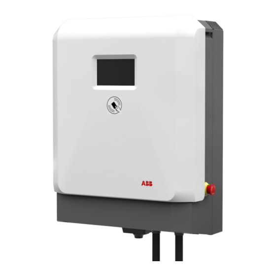
Page 11: External View
TER R A DC WAL LB OX 2.1.2 External view Display / HMI Emergency stop button RFID card reader AC input connection point for Conduit or Cable DC Charging cable Air inlet Air outlet Standard Holster (included) Optional Holster (purchased separately) FIG. -
Page 12: Inside View
TER R A DC WAL LB OX 2.1.3 Inside view AC input board D Cable gland for DC output(2x) CPI and IMI boards E Cable gland for AC input External Fan (2x) 2 0 2 0- 0 8- 0 6 1 2 / 41... -
Page 13: Site Design
Evaluate cellular connection The Terra DC Wallbox includes a 4G modem equipped with a GSM SIM card. When selecting the site, it is ex- pected that a cellular availability test is performed. Recommended signal strength is >-85dbm, (-30dBm to - 85dBM is the optimum signal strength), this should be measured with a cellular network signal meter, handheld mobile phones are not always reliable measuring devices. -
Page 14: Conductor And Cable Diameter
TER R A DC WAL LB OX 480Y/277V 3-phase unit 208Y/120V 1-phase unit 120/240V 1-phase unit CAUTION Responsibility to comply with local regulations The installation company is responsible to design and install the electrical installation according to the local regulations. 3.3.1 Conductor and cable diameter The diameter of the ground cables’... -
Page 15: Short Circuit Current Rating
- Bottom side 23.6” (15.75” from the Terra DC Wallbox in order to avoid obstacles for the electrical connec- tion). - Left and right side 12”, in order to operate without obstacles on the lateral side of the Terra DC Wallbox. 3.4.2 Ventilation and airflow of the Terra DC Wallbox The Terra DC Wallbox has an air inlet on the bottom side and an outlet on the top side. -
Page 16: Cable Reach
Cable reach The Terra DC Wallbox charging cables are available in lengths of 3.5 or 7 meters. The charging cables exit the charger enclosure on both the right and left sides. The cables and the connectors mounted on the cables are different depending on the charging standard and vary in flexibility. -
Page 17: Different Alignment Possibilities
TER R A DC WAL LB OX Different alignment possibilities The charging inlets on a vehicle can be located at different positions depending on the manufacturer. The most common vehicles have inlets located either on the front or in the back on either the left or right side. This makes some charger placements with respect to the parking space more favorable than others. -
Page 18: Site Construction
About construction The construction phase includes all work required to prepare the location and ensure it is ready for the placement and connection of the Terra DC Wallbox charger. The construction phase can start when: • The wall preparation work is done. -
Page 19: Instruction For A Wall Bearing
Mounting on a pedestal The Terra DC Wallbox can also be mounted on a pedestal. In order to achieve a safe installation, the mini- mum set of requirements are included in Appendix C – Pedestal requirements). For the ABB pedestal solu- tion, contact your local ABB sales representative. -
Page 20: Internet Connection
The preferred method of communication is the wireless 4G modem integrated into the charger. A customer SIM card is not required. A subscription for the SIM card is provided by ABB for select countries. If there is no wireless signal available, a standard wired internet connection is required. This connection must meet the following requirements: Ethernet, RJ45. -
Page 21: Receiving, Placing And Connecting
Receiving the Wallbox The product is delivered by a transport company to a warehouse where it will be handed over. Transporting the Terra DC Wallbox to its final location (last mile service) is not included standard in the order. NOTICE The delivery truck unloads the pallet carrying the Terra DC Wallbox. -
Page 22: Mounting Preparations
• Two bolts M5 • 4. Remove the wall frame. 5. Remove the Terra DC Wallbox. (USE CAUTION TO NOT DAMAGE THE E-STOP BUTTON ON THE SIDE OF THE ENCLOSURE) 6. For all components above, remove the shrink wrap. 5.2.2... -
Page 23: Move Cabinet To Position
Bottom grid cover Move cabinet to position 5.3.1 Options A properly rated lifting devices should be used to move the Terra DC Wallbox from the delivery truck to the installation location. DANGER Hazardous voltage Ensure the product’s power supply group main switch is set to the OFF position. -
Page 24: Mounting The Terra Dc Wallbox
5.4.1 Mounting the Terra DC Wallbox NOTICE A minimum of two people are required to lift a Terra DC Wallbox during installation. In general, local regulations should be followed as the maximum weight to be lifted may vary. 1. Carefully lower the Terra DC Wallbox onto its location. - Page 25 TER R A DC WAL LB OX 6. Tighten the two M5 bolts on the lower side of the unit. Pay attention to the internal fan power supply cable. CAUTION: DO NOT SET SMALL OBJECTS ON TOP MESH COVER, ITEMS MAY FALL INTO THE COOLING FINS OR FAN COMPONENTS.
- Page 26 TER R A DC WAL LB OX 8. IMPORTANT, connect both of the cooling fans to their power connections before proceeding to close the covers. There are two connectors one for the left fan and one for the right fan. 9.
- Page 27 TER R A DC WAL LB OX 10. Take the lower frontal cover and place it on the lower side of the unit. Secure it in place by tightening the two screws. 11. Center the holes on the plastic cover with the pins on the box. 12.
-
Page 28: Install Cable Gland(S) Or Connect Conduit To The Unit
TER R A DC WAL LB OX 13. ADA Compliance: For public facing units, they must be installed to meet ADA compliance regardless if mounted on a wall or on a pedestal. https://afdc.energy.gov/files/u/publication/WPCC_complyingwithADArequirements_1114.pdf 5.4.2 Install cable gland(s) or connect conduit to the unit. The maximum diameter of the grid cable is 32 mm. - Page 29 TER R A DC WAL LB OX 208/240V 1-phase version Wire pass thru locations 2. Push the cables back through the gland plate, until sufficient cable length is left to reach the cable termi- nals. Ensure the PE cable is longer than the other cables. Conduit Installation 1.25“...
-
Page 30: Connect Cables
TER R A DC WAL LB OX to be inserted in the AC in cable and located in the screw cable cover (see picture below, left). THE FERRITE IS REQUIRED TO MAINTAIN THE WARRANTY. NOTE 2: A floating grounding cable is provided that is connected to the ground node. The mentioned cable has to be connected to the wall frame PEM in order to guarantee equal ground potential (see picture below, right). -
Page 31: Connect Power Cable
TER R A DC WAL LB OX 5.5.2 Connect power cable Preconditions: • Tools: Wire stripper pliers; wire-end lug pliers; wire-end lugs. DANGER Hazardous voltage Ensure the product’s power supply group’s main switch is set to the OFF position. Perform a voltage check and ensure the electrical power is disconnected from the system. -
Page 32: Connect Network Cable
Connect network cable WARNING Leave the main switch in the off position. The Terra DC Wallbox is not ready for use yet. Please contact the ABB Service department at least one week in advance to make an appointment for commissioning. -
Page 33: Commissioning
Commissioning Commissioning preparation Commissioning is the last phase necessary to get the Terra DC Wallbox operational. The purpose is to check the safe functioning of the charger for its operational purpose. A certified service engineer from the ABB Service department or a trained engineer by ABB is required to perform the commissioning. - Page 34 TER R A DC WAL LB OX 2 0 2 0- 0 8- 0 6 3 4 / 41...
-
Page 35: Maintenance And Cleaning Of The Cabinet
Using the connected network verify charging session details. Cleaning of the cabinet The Terra DC Wallbox Charger is powder coated. This coating must be kept in good condition. Clean the Terra DC Wallbox Charger three times a year in the following way: •... -
Page 36: Technical Data
TER R A DC WAL LB OX Technical Data Electrical data AC Input Supply voltage (1) 1 phase / 2 phases, 208 V AC/240 V AC: PE, L1, L2 (2) 3 phase, 277/480 V AC: PE, N, L1, L2, L3 Input voltage range (1) 208V AC/240 V AC +10%, -15% (60 Hz) (2) 480 V AC +10%, -15% (60Hz) -
Page 37: Mechanical Data
TER R A DC WAL LB OX Mechanical data Mechanical data Dimensions (H x W x D) 770 mm x 585 mm x 300 mm / 30.32” x 23.03” x 11.81” Weight 70 kg / 154.32lbs Volume 0,135 m3 Dimensions including packaging (H X W x D) 650 mm x 1200 mm x 800 mm /25.6”... -
Page 38: Contact Information
In case they cannot solve the problem, they will contact the second line Service organization. ABB in your country Please contact ABB in your country for sales, delivery and service information. ABB EV Infrastructure USA ABB Inc. -
Page 39: Appendix A - Mounting Points
TER R A DC WAL LB OX Appendix A – Mounting points 10.1 Terra DC Wallbox Charger wall mounting 2 0 2 0- 0 8- 0 6 3 9 / 41... -
Page 40: Appendix B - Disposal Instruction
TER R A DC WAL LB OX Appendix B - Disposal instruction 11.1 Directive on Waste Electrical and Electronic Equipment (WEEE – 2012/19/EU) 2 0 2 0- 0 8- 0 6 4 0 / 41... -
Page 41: Appendix C - Pedestal Requirements
TER R A DC WAL LB OX Appendix C – Pedestal requirements Any pedestal solution designed for Terra DC wallbox needs to fulfill the specific ISO standards for civil con- tructions (note: specific local regulations may apply). Additionally, whereas no specific contraint is provided by local regulations, the minimum set of requirements necessary to provide a safe installation are listed in the table below to be verified in the temperature range between -50°C - +60°C:...
Need help?
Do you have a question about the Terra DC Wallbox and is the answer not in the manual?
Questions and answers