ABB Terra DC Wallbox Installation Manual
Hide thumbs
Also See for Terra DC Wallbox:
- Installation manual (41 pages) ,
- User's operation manual (20 pages) ,
- Quick start manual (2 pages)
Table of Contents
Advertisement
Advertisement
Table of Contents

Related Manuals for ABB Terra DC Wallbox


Summary of Contents for ABB Terra DC Wallbox
- Page 1 — MA NUAL: NO RTH A MERICA Terra DC Wallbox Installation Manual...
- Page 2 This document and parts thereof must not be reproduced or copied without written permission from ABB, and the contents thereof must not be imparted to a third party nor used for any unau- thorized purpose.
-
Page 3: Table Of Contents
Contents 1 Introduction ..............................6 Preface ..............................6 Intended document users ........................6 Terra DC Wallbox hardware ordering details.................... 6 Signs ..............................7 Owner responsibilities ......................8 1.4.1 Tilting and handling ........................ 9 1.4.2 Sharp edges ........................... 9 1.4.3 Electric hazards ........................9 1.4.4... - Page 4 9 Contact information ............................40 10 Appendix A – Mounting points ........................41 10.1 Terra DC Wallbox Charger wall mounting ....................41 11 Appendix B - Disposal instruction ........................42 11.1 Directive on Waste Electrical and Electronic Equipment (WEEE – 2012/19/EU) ........42...
- Page 5 Grid provider Company responsible for the transportation and distribution of electricity. Human Machine Interface; the display/screen on the charger. ABB Network Operating Centre; remotely checks the correct functioning of the charger. Owner The legal owner of the charger. OCPP Open Charge Point Protocol. Open standard for communication with charge stations.
-
Page 6: Introduction
This guide provides an overview for the installation of the Terra DC Wallbox. The Terra DC Wallbox charging station is an easy to install DC fast charger for electric vehicles. Fast chargers are electrical installations with high electric currents. Therefore, the installation must be planned carefully, and must be done by certified personnel only (according to local standards). -
Page 7: Signs
TE R R A D C WA LL B OX Optional connector holsters shown below may be purchased separately with the order code details shown below. Charging cable type ABB order code CCS-1 ABB6AGC076604 CHAdeMO ABB6AGC076601 Signs The following signs are used on the equipment and in this manual:... -
Page 8: Owner Responsibilities
ABB’s warranty policy. Neither ABB nor its affiliates shall be liable to the purchaser of this product or third parties for damages, losses, costs or expenses incurred by purchaser or third parties as a result of: an accident, misuse or abuse of this product or unauthorized modifications, repairs or alterations to this product, or failure to strictly comply with ABB’s operating and... -
Page 9: Tilting And Handling
2. Do not drop the Terra DC Wallbox. 1.4.3 Sharp edges WARNING Sharp metal edges There could be sharp metal edges inside the Terra DC Wallbox. It is recommended to wear mash protecting gloves when working inside the charger. 1.4.4 Electric hazards... -
Page 10: Environment And Disposal Of Waste
Instruct and warn people about the potentially harmful high voltages. 5. The installation and maintenance personnel must supply their own lighting equipment because the Terra DC Wallbox has no lights inside the cabinet. 6. Always connect the Protective Earth (PE) first, before connecting the other power input wires. -
Page 11: Description Of The Product
Overview of the system 2.1.1 Complete overview Example of a complete installation Power distribution board of the owner Cables in conduit Terra DC Wallbox Parking space for charging Electric vehicle 2 0 2 0 - 1 2 11 /4 4... -
Page 12: External View
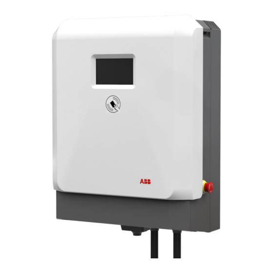
TE R R A D C WA LL B OX 2.1.2 External view Display / HMI Emergency stop button RFID card reader AC input connection point for Conduit DC Charging cable Air inlet Air outlet Standard Holster (included) Optional Holster (purchased separately) Standard charging cable Optional charging cable holster supplied with DC... -
Page 13: Inside View
TE R R A D C WA LL B OX 2.1.3 Inside view AC input board D Cable gland for DC output(2x) CPI and IMI boards E Cable gland for AC input External Fan (2x) 2 0 2 0 - 1 2 13 /4 4... -
Page 14: Installation Planning And Design
Squid-4G or Sure Call device. Handheld mobile phones are not recommended for assessing signal strength since they are not reliable measuring devices. The DC Wallbox only supports SIM cards provided by ABB. Customer procured SIM cards are not supported. 3.1.2... -
Page 15: Electrical Requirements
Please observe the 3-phase variant DC Wallbox supports only one grid configuration and the 1-phase variant DC Wallbox supports two different grid configurations. For the 1-phase variant DC Wallbox, ABB recommends the electrical designer to consider power distribution phase balancing design requirements. 40A fused... - Page 16 TE R R A D C WA LL B OX 125A fused switch or circuit breaker Line 1 208V Line 2 Line 1 120V Neutral 208V 1-phase 208V Terra DC Line 3 Line 2 Wallbox Ground Grounding Electrode Conductor One of two electrical grid configurations acceptable for use with 1-phase, DC Wallbox UL vari- ant (1ø, 208V input) 125A fused switch or circuit...
-
Page 17: Overcurrent Protection Device
DC Wallbox commissioning. ABB is not responsible for scheduling delays and additional costs from not properly planning the installation. If ABB is contracted to perform the DC Wallbox commissioning, ABB observes the right to charge additional money for more than one site visit required for the commissioning due to an initial, improper installation of the DC Wallbox. -
Page 18: Conduit For Ethernet Cable
Charging cable reach The Terra DC Wallbox charging cables are available in lengths of 3.5 or 7 meters. The charging cables exit the charger enclosure on both the right and left sides. The cables and the connectors mounted on the cables are dif- ferent depending on the charging standard and vary in flexibility. -
Page 19: Dc Wallbox Position With Respect To Parking Space
TE R R A D C WA LL B OX 3.3.2 DC Wallbox position with respect to parking space The charging inlets on a vehicle can be located at different positions depending on the manufacturer. The most common vehicles have inlets located either on the front or in the back on either the left or right side. This makes some charger placements with respect to the parking space more favorable than others. -
Page 20: Required Space For Installing And Maintaining The Dc Wallbox
- Charger size (H x W x D): 30.3 x 23 x 11.8 in - Bottom side 23.6” (15.75” from the Terra DC Wallbox in order to avoid obstacles for the electrical connection). - Left and right side 300mm/12”, in order to operate without obstacles on the lateral side of the Terra DC Wall- box. -
Page 21: Ventilation And Airflow Required For The Dc Wallbox
TE R R A D C WA LL B OX 3.3.4 Ventilation and airflow required for the DC Wallbox The Terra DC Wallbox has an air inlet on the bottom side and an outlet on the top side. NOTICE Free air flow If necessary, take precautions to prevent snow or objects from blocking the inlets and outlets. - Page 22 TE R R A D C WA LL B OX 2 0 2 0 - 1 2 2 2 /4 4...
-
Page 23: Installation Instructions
Mounting on a pedestal The Terra DC Wallbox can also be mounted on a pedestal. In order to achieve a safe installation, the minimum set of requirements are included in Appendix C – Pedestal requirements). For the ABB pedestal solution, contact your local ABB sales representative. -
Page 24: Receiving, Placing And Connecting
Receiving the Wallbox The product is delivered by a transport company to a warehouse where it will be handed over. Transporting the Terra DC Wallbox to its final location (last mile service) is not included standard in the order. NOTICE The delivery truck unloads the pallet carrying the Terra DC Wallbox. -
Page 25: Unpacking The Charging And Mounting Preparations
TE R R A D C WA LL B OX Unpacking the charging and mounting preparations 5.2.1 Unpacking The packaging of the Terra DC Wallbox can be removed without the use of tools. Follow local regulations on dis- posal of packaging material. Bottom Cover Grill 1. -
Page 26: Move Cabinet To Position
Bottom grid cover Move cabinet to position 5.3.1 Options A properly rated lifting devices should be used to move the Terra DC Wallbox from the delivery truck to the in- stallation location. DANGER Hazardous voltage Ensure the product’s power supply group main switch is set to the OFF position. -
Page 27: Mounting The Terra Dc Wallbox
5.4.1 Mounting the Terra DC Wallbox NOTICE A minimum of two people are required to lift a Terra DC Wallbox during installation. In general, local regulations should be followed as the maximum weight to be lifted may vary. 1. Carefully lower the Terra DC Wallbox onto its location. - Page 28 TE R R A D C WA LL B OX 5. Place the unit on the wall frame by correctly aligning the 6 bolts (3 for each lateral side). 6. Tighten the two M5 bolts on the lower side of the unit. Pay attention to the internal fan power supply ca- ble.
- Page 29 TE R R A D C WA LL B OX 7. Let the auxiliary power supply cable pass through the central gland and tighten it. 8. IMPORTANT, connect both of the cooling fans to their power connections before proceeding to close the covers.
- Page 30 TE R R A D C WA LL B OX 9. AFTER the completing wiring terminations, take the bottom cover grill and put it on the lower side of the unit and fix it by tightening two screws as shown in the following picture. Please note the 3-phase and 1- phase versions have a slightly different bottom grill assembly 10.
-
Page 31: Install Cable Gland(S) Or Connect Conduit To The Unit
TE R R A D C WA LL B OX 12. Place the central cover on the unit and secure it in place by tightening the two screws located on the left and right side of the cover. Center the bottom pins, rotate the cover, and tighten the 2 lateral screws. 5.4.2 Install cable gland(s) or connect conduit to the unit. - Page 32 TE R R A D C WA LL B OX 1. Slide the cable inside the grommets, ensure at least 10mm of cable external jacket inside the box (see notes at the end of this section, before sliding the cable inside the grommet. Allow at least 24 inches of wire from the conduit entry point to allow enough wire to route thru the internal grommet/cable glands and wrap around to the terminal blocks.
-
Page 33: Connect Cables
TE R R A D C WA LL B OX Conduit Installation 1.25“ secured to bottom mounting area. 1-phase Version Shown 3-Phase Connection using flexible conduit 3. Slide the cable cover and tighten the two screws. If a wired internet connection is not used, please ensure the cable entry hole is closed, to assure the IP54 grade of the cabinet, and prevent insects and small animals to enter the cabinet. -
Page 34: Connect Power Cable
TE R R A D C WA LL B OX 1. Cut the PE wire of the power cable to the correct length (longer than the other phases) to reach the PE con- nector. NOTICE For safety, it is recommended that the PE wire is longer than the phase wires. - Page 35 TE R R A D C WA LL B OX • From left to right for the 1-phase unit (as showed in the following picture): PE- terminal block green/yellow, L2 - terminal block grey, L1 - terminal block grey L2 L1 208/240V 1-phase terminal layout 12.
-
Page 36: Commissioning
Commissioning Commissioning preparation Commissioning is the last phase necessary to get the Terra DC Wallbox operational. The purpose is to check the safe functioning of the charger for its operational purpose. An ABB certified service engineer or an ABB-trained engineer is required to perform the commissioning. During this commissioning, the safety and the functioning of the charger will be tested. -
Page 37: Maintenance And Cleaning Of The Cabinet
Using the connected network verify charging session details. Cleaning of the cabinet The Terra DC Wallbox Charger is powder coated. This coating must be kept in good condition. Clean the Terra DC Wallbox Charger three times a year in the following way: •... -
Page 38: Technical Data
TE R R A D C WA LL B OX Technical Data Electrical data AC Input AC input voltage range (1) 208 - 240 V +/- 10% (60Hz) (2) 480 V +/- 10% (60Hz) AC input power connection (1) 1-phase, 208-240 V : L1, L2, GND (2) 3-phase, 480Y/277 V : L1, L2, L3, N,... -
Page 39: Mechanical Data
TE R R A D C WA LL B OX Mechanical data Mechanical data Dimensions (H x W x D) 770 mm x 585 mm x 300 mm / 30.32” x 23.03” x 11.81” Weight 70 kg / 154.32lbs Volume 0,135 m3 Dimensions including packaging (H X W x D) 650 mm x 1200 mm x 800 mm /25.6”... -
Page 40: Contact Information
In case they cannot solve the problem, they will contact the second line Service organization. ABB in your country Please contact ABB in your country for sales, delivery and service information. ABB EV Infrastructure USA ABB Inc. -
Page 41: Appendix A - Mounting Points
TE R R A D C WA LL B OX Appendix A – Mounting points 10.1 Terra DC Wallbox Charger wall mounting 2 0 2 0 - 1 2 41 /4 4... -
Page 42: Appendix B - Disposal Instruction
TE R R A D C WA LL B OX Appendix B - Disposal instruction 11.1 Directive on Waste Electrical and Electronic Equipment (WEEE – 2012/19/EU) 2 0 2 0 - 1 2 42 / 4 4... -
Page 43: Appendix C - Pedestal Requirements
TE R R A D C WA LL B OX Appendix C – Pedestal requirements Any pedestal solution designed for Terra DC Wallbox needs to fulfill the specific ISO standards for civil contruc- tions (note: specific local regulations may apply). - Page 44 TE R R A D C WA LL B OX www.abb.com/evcharging 2 0 2 0 - 1 2 4 4/4 4...
Need help?
Do you have a question about the Terra DC Wallbox and is the answer not in the manual?
Questions and answers