
Related Manuals for ABB Terra DC Wallbox C UL


Summary of Contents for ABB Terra DC Wallbox C UL
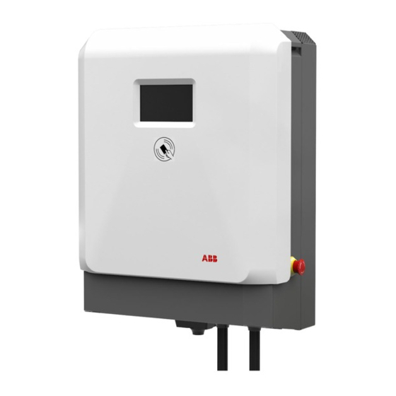
- Page 1 — M ANUAL : NOR TH AMER IC A Terra DC Wallbox UL Three-phase Version Installation Manual Rev 2.1...
- Page 2 This document contains information about one or more ABB products and may include a description of or a reference to one or more standards that may be generally relevant to the ABB products. The pres- ence of any such description of a standard or reference to a standard is not a representation that all of the ABB products referenced in this document support all of the features of the described or referenced standard.
-
Page 3: Table Of Contents
Contents 1 Introduction ............................6 Preface..............................6 Intended document users ........................6 Terra DC Wallbox hardware ordering details .................. 6 Signs ................................ 7 1.4.1 Owner responsibilities......................8 1.4.2 Tilting and handling ......................9 1.4.3 Sharp edges .......................... 9 1.4.4 Electric hazards ........................9 1.4.5 Installation safety ........................ - Page 4 5.3.1 Options ..........................23 Mounting the Terra DC Wallbox ....................... 23 5.4.1 Mounting the Terra DC Wallbox ..................23 5.4.2 Install cable gland(s) or connect conduit to the unit..........28 Connect cables ........................... 29 5.5.1 Connect PE of power cable ....................29 5.5.2 Connect power cable ......................
- Page 5 Grid provider Company responsible for the transportation and distribution of electricity. Human Machine Interface; the display/screen on the charger. ABB Network Operating Centre; remotely checks the correct functioning of the charger. Owner The legal owner of the charger. OCPP Open Charge Point Protocol. Open standard for communication with charge stations.
-
Page 6: Introduction
Before installing the Terra DC Wallbox, read this installation guide carefully and attentively. Be sure to follow all instructions when installing the charger. ABB is not responsible for any damage caused by not following or incorrectly executing the instructions described in this manual. -
Page 7: Signs
T ER R A DC WA LL BOX U L Optional connector holsters shown below may be purchased separately with the order code details shown below. Charging cable type ABB order code CCS-1 ABB6AGC076604 CHAdeMO ABB6AGC076601 Signs The following signs are used on the equipment and in this manual:... -
Page 8: Owner Responsibilities
ABB’s warranty policy. Neither ABB nor its affiliates shall be liable to the purchaser of this product or third parties for dam- ages, losses, costs or expenses incurred by purchaser or third parties as a result of: an accident, misuse or abuse of this product or unauthorized modifications, repairs or alterations to this product, or failure to strictly comply with ABB’s operating and maintenance instructions. -
Page 9: Tilting And Handling
2. Perform a voltage check to ensure electrical power is discon- nected from the system. 3. Only ABB certified technicians should commission the Terra DC Wallbox. 4. When the system is in an open or dangerous condition, do not al- low unqualified persons to go near it. -
Page 10: Environment And Disposal Of Waste
T ER R A DC WA LL BOX U L Environment and disposal of waste NOTICE Always follow the local rules and regulations regarding disposal of any (non-reusable) Terra DC Wallbox parts. Description of the product Overview of the system 2.1.1 Complete overview Example of a complete installation... -
Page 11: External View
T ER R A DC WA LL BOX U L 2.1.2 External view Display / HMI Emergency stop button RFID card reader AC input connection point for Conduit DC Charging cable Air inlet Air outlet Standard Holster (included) Optional Holster (purchased separately) Standard charging Optional charging cable cable holster supplied... -
Page 12: Inside View
T ER R A DC WA LL BOX U L 2.1.3 Inside view AC input board D Cable gland for DC output(2x) CPI and IMI boards E Cable gland for AC input External Fan (2x) 20 2 0- 10- 05 1 2/ 3 8... -
Page 13: Installation Planning And Design
Squid-4G or Sure Call device. Handheld mobile phones are not recommended for as- sessing signal strength since they are not reliable measuring devices. The Terra DC Wallbox only supports SIM cards provided by ABB. Customer procured SIM cards are not supported. -
Page 14: Required Electrical Grid Configuration
T ER R A DC WA LL BOX U L 3.2.1 Required electrical grid configuration It is essential that the Terra DC Wallbox 3-phase input variant is installed in the proper electrical grid configuration. The allowable grid configuration is shown in the figure below. 40A fused switch or circuit breaker... -
Page 15: Overcurrent Protection Device
The 3-phase UL variant Terra DC Wallbox requires Three (3) phase wires, One (1) neutral wire, and One (1) wire for protective earth. (3W+N+G) All wires for 3-phase variants of the Terra DC Wallbox may connect directly to the ABB provided termi- installer to nals, with exception to the protective earth wire. -
Page 16: Conduit For Ethernet Cable
The Terra DC Wallbox does not have a hole designated for a conduit carrying only an ethernet cable to connect to. If ethernet cable solution is required for an installation, please contact your ABB sales con- tact person to review ethernet cable entry solutions. -
Page 17: Terra Dc Wallbox Position With Respect To Parking Space
T ER R A DC WA LL BOX U L 3.3.2 Terra DC Wallbox position with respect to parking space The charging inlets on a vehicle can be located at different positions depending on the manufacturer. The most common vehicles have inlets located either on the front or in the back on either the left or right side. -
Page 18: Required Space For Installing And Maintaining The Terra Dc Wallbox
T ER R A DC WA LL BOX U L 3.3.3 Required space for installing and maintaining the Terra DC Wallbox The Terra DC Wallbox requires a minimum space of 36” x 48”. This space is calculated as follows: - Charger size (H x W x D): 30.3 x 23 x 11.8 in - Bottom side 23.6”... -
Page 19: Ventilation And Airflow Required For The Terra Dc Wallbox
T ER R A DC WA LL BOX U L 3.3.4 Ventilation and airflow required for the Terra DC Wallbox The Terra DC Wallbox has an air inlet on the bottom side and an outlet on the top side. NOTICE Free air flow If necessary, take precautions to prevent snow or objects from blocking the inlets and outlets. -
Page 20: Installation Instructions
The preferred method of communication is the wireless 4G modem integrated into the charger. A cus- tomer SIM card is not required. A subscription for the SIM card is provided by ABB for select countries. If there is no wireless signal available, a standard wired internet connection is required. (Reference Sec- tion 3.1, 3.2.5 and 3.2.6 for wiring and connection methods) -
Page 21: Receiving, Placing And Connecting
Make a notation on the delivery receipt and inspect cabinet for damage. If damage is discovered, leave cabinet in original package and request immediate inspection from carrier within 3 days of delivery. Contact your local ABB office. Unpacking the charging and mounting preparations 5.2.1 Unpacking The packaging of the Terra DC Wallbox can be removed without the use of tools. -
Page 22: Mounting Preparations
T ER R A DC WA LL BOX U L Bottom Cover Grill Remove the plastic protection profiles. Remove the bottom air grate grill and the lower frontal cover. Remove the wall frame. Remove the Terra DC Wallbox. (USE CAUTION TO NOT DAMAGE THE E-STOP BUTTON ON THE SIDE OF THE ENCLOSURE) Remove the AC ferrite core link to the outlet gun cable (assembly position shown at paragraph 5.4.2) -
Page 23: Move Cabinet To Position
T ER R A DC WA LL BOX U L Move cabinet to position 5.3.1 Options A properly rated lifting devices should be used to move the Terra DC Wallbox from the delivery truck to the installation location. DANGER Hazardous voltage Ensure the product’s power supply group main switch is set to the OFF position. - Page 24 T ER R A DC WA LL BOX U L 2. Ensure cable(s) are not entrapped. 3. Place the wall frame in the correct position on the wall bearing by aligning the four holes of the charger with the corresponding holes on the wall bearing. 4.
- Page 25 T ER R A DC WA LL BOX U L 6. Tighten the two M5 bolts on the lower side of the unit. Pay attention to the internal fan power sup- ply cable. CAUTION: DO NOT SET SMALL OBJECTS ON TOP MESH COVER, ITEMS MAY FALL INTO THE COOLING FINS OR FAN COMPONENTS.
- Page 26 T ER R A DC WA LL BOX U L 8. IMPORTANT, connect both of the cooling fans to their power connections before proceeding to close the covers. There are two connectors one for the left fan and one for the right fan. 9.
- Page 27 T ER R A DC WA LL BOX U L 10. Take the lower frontal cover and place it on the lower side of the unit. Secure it in place by tighten- ing the two screws. 11. Center the holes on the plastic cover with the pins on the box. 12.
-
Page 28: Install Cable Gland(S) Or Connect Conduit To The Unit
T ER R A DC WA LL BOX U L 5.4.2 Install cable gland(s) or connect conduit to the unit. The maximum diameter of the grid cable is 32 mm. The opening is pre-punched for a 1.25” trade size conduit. The minimum diameter of the grid cable is 22 mm with the standard fitted cable gland insert. Conduit Install shown as a comparison 1. -
Page 29: Connect Cables
T ER R A DC WA LL BOX U L 2. Push the cables back through the gland plate, until sufficient cable length is left to reach the cable terminals. Ensure the PE cable is longer than the other cables. Conduit Installation 1.25“... -
Page 30: Connect Power Cable
T ER R A DC WA LL BOX U L NOTICE For safety, it is recommended that the PE wire is longer than the phase wires. This ensures the PE wire will be the last wire con- nected if the Terra DC Wallbox is moved by a collision. 2. -
Page 31: Commissioning
A certified service engineer from the ABB Service department or a trained engineer by ABB is required to perform the commissioning. During this commissioning, the safety and the functioning of the charger will be tested. -
Page 32: Maintenance And Cleaning Of The Cabinet
T ER R A DC WA LL BOX U L Maintenance and Cleaning of the cabinet Recommended Periodic maintenance NFPA-70e Following procedures, de-energize unit, open cover, inspect air filter, clean or replace as needed. Check input connections and terminations for proper toque values Check Grounding resistance D. -
Page 33: Technical Data
T ER R A DC WA LL BOX U L Technical Data Electrical data AC Input 480 V +/- 10% (60Hz) AC input voltage range AC input power connection 3-phase, 480Y/277 V : L1, L2, L3, N, GND Maximum rated input current at nominal 32 A voltage Recommended upstream overcurrent pro-... -
Page 34: Mechanical Data
T ER R A DC WA LL BOX U L Mechanical data Mechanical data Dimensions (H x W x D) 770 mm x 585 mm x 300 mm / 30.32” x 23.03” x 11.81” Weight 70 kg / 154.32lbs Volume 0,135 m3 Dimensions including packaging (H X 650 mm x 1200 mm x 800 mm /25.6”... -
Page 35: Contact Information
For technical support in North America, please visit the ABB E-mobility Service & Resource Portal. For all other regions, please contact your local ABB Service organization or Service partner for first line problem analysis and solving. 20 2 0- 10- 05... -
Page 36: Appendix A - Mounting Points
T ER R A DC WA LL BOX U L Appendix A – Mounting points 10.1 Terra DC Wallbox Charger wall mounting 20 2 0- 10- 05 36 / 38... -
Page 37: Appendix B - Disposal Instruction
T ER R A DC WA LL BOX U L Appendix B - Disposal instruction 11.1 Directive on Waste Electrical and Electronic Equipment (WEEE – 2012/19/EU) 20 2 0- 10- 05 37 / 38... -
Page 38: Appendix C - Pedestal Requirements
T ER R A DC WA LL BOX U L Appendix C – Pedestal requirements Any pedestal solution designed for Terra DC Wallbox needs to fulfill the specific ISO standards for civil constructions (note: specific local regulations may apply). Additionally, whereas no specific constraint is provided by local regulations, the minimum set of re- quirements necessary to provide a safe installation are listed in the table below to be verified in the temperature range between -50°C - +60°C: Minimum Wind load resistance...
Need help?
Do you have a question about the Terra DC Wallbox C UL and is the answer not in the manual?
Questions and answers