Advertisement
PROPER USE GUIDELINES
Cumulative Trauma Disorders can result from the prolonged use of manually powered hand tools. Hand tools are intended for occasional use
and low volume applications. A wide selection of powered application equipment for extended-use, production operations is available.
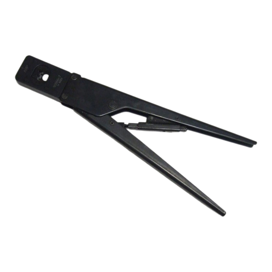
Crimpers
Front of Tool
(Contact Side)
Anvils
Ratchet
Figure 1
1. INTRODUCTION
Hand Crimping Tool 90066-7 and Head Assembly
90066-9 (shown in Figure 1) are designed to crimp
Type III+ and Type VI, and commercial MATE-N-LOK*
contacts listed in Figure 2. Read these instructions
thoroughly before crimping any contacts.
All dimensions on this document are in metric units
NOTE
[with U.S. customary units in brackets]. Figures and
illustrations are for reference only and are not
i
drawn to scale.
Reasons for reissue of this instruction sheet are
provided in Section 6, REVISION SUMMARY.
2. DESCRIPTION
(Figures 1 and 2)
The front of the tool (contact side), into which the
contact is inserted, has the tool number marked on it.
©2011 Tyco Electronics Corporation, a TE Connectivity Ltd. Company
All Rights Reserved
*Trademark
TE Connectivity, TE connectivity (logo), and TE (logo) are trademarks. Other logos, product and/or Company names may be trademarks of their respective owners.
CERTI-CRIMP* Hand Crimping
Tool 90066-7 and Head
Assembly 90066-9
The back of the tool (wire side), into which the wire is
inserted, has the wire size and color-code dots
marked above each crimping chamber.
Contact
Support
The tool features two fixed dies (crimpers), two
movable dies (anvils), two crimping chambers, a
contact support, a locator/insulation stop, an ejector,
and ratchet.
The ratchet ensures full crimping of the contact. Once
engaged, the ratchet will not release until the handles
have been FULLY closed.
The locator/insulation stop has two functions. First, it
positions the contact between the crimping dies, and
second, it aids in locating the wire in the contact. In
use, it rests in the locator slot. See Figures 2 and 3.
The contact support prevents the contact from
bending during crimping. The ejector pulls the locator
down and ejects the crimped contact when the tool
handles are FULLY opened.
3. CRIMPING PROCEDURE
Refer to Figure 2, and select wire of the specified size
and insulation diameter for the type and part number
of loose piece contact. Strip the wire to the length
indicated. DO NOT cut or nick the wire strands.
On the BACK of the tool, identify the appropriate
crimping chamber (according to the color dot and/or
wire size markings). The markings on the contact must
match the markings on the appropriate crimping
chamber of the tool.
Refer to Figure 3, and proceed as follows:
TOOLING ASSISTANCE CENTER 1-800-722-1111
PRODUCT INFORMATION 1-800-522-6752
The dies bottom before the ratchet releases.
CAUTION
This is feature ensures maximum electrical and
tensile performance of the crimp. DO NOT re-
!
adjust the ratchet.
Type III+ contacts have a color dot located on the
NOTE
contact spring. Type VI contacts have the
applicable wire size stamped on the underside of
i
the insulation barrel.
1. Hold the tool so the BACK (wire side) is facing
you.
2. Make sure the ratchet is released by squeezing
the handles and allowing them to open FULLY.
3. Insert the contact (insulation barrel first) into the
FRONT of appropriate crimping chamber. Position
the contact in the crimpers so that the locator enters
the locator slot of the contact.
This controlled document is subject to change.
For latest revision and Regional Customer Service,
visit our website at www.te.com
Instruction Sheet
408-6610
26 SEP 11 Rev E
1 of 4
LOC B
Advertisement
Table of Contents

Related Manuals for TE Connectivity CERTI-CRIMP 90066-7


Summary of Contents for TE Connectivity CERTI-CRIMP 90066-7
- Page 1 PRODUCT INFORMATION 1-800-522-6752 For latest revision and Regional Customer Service, *Trademark visit our website at www.te.com LOC B TE Connectivity, TE connectivity (logo), and TE (logo) are trademarks. Other logos, product and/or Company names may be trademarks of their respective owners.
- Page 2 408-6610 WIRE CONTACT CRIMPING CHAMBER CRIMP DOT LOOSE PIECE STRIP SIZE INSULATION (Wire Size CODE TYPE (AWG) DIAMETER SOCKET SOCKET Marking) 1.02-1.52 24-20 30-26 III+ 66429 66428 66425 66424 2 Dots [.040-.060] 30-26 28-24 66595 66596 66585 66586 0.89-1.40 28-24 1 Dot [.035-.055] 30-22...
- Page 3 408-6610 4.2. Periodic Inspection Special precautions must be taken when inserting a CAUTION wire into a contact crimped in the crimping chamber At least one inspection a month is recommended and marked “24-20/30-26”. The full length of the the inspection frequency should be based on the stripped wire must rest on the bottom of the wire amount of use, ambient working conditions, operator barrel.
- Page 4 408-6610 2. Position the contact and wire in the dies, as described in Section 3, CRIMPING PROCEDURE. 3. Holding the wire in place, squeeze the handles until the ratchet releases. Hold the handles in this position, maintaining just enough tension to keep the dies closed.
Need help?
Do you have a question about the CERTI-CRIMP 90066-7 and is the answer not in the manual?
Questions and answers