Advertisement
Quick Links
Advertisement

Subscribe to Our Youtube Channel
Related Manuals for Xilinx ML631


Summary of Contents for Xilinx ML631
- Page 1 ML631 GTX Chip to Chip IBERT October 2011 XTP128 © Copyright 2011 Xilinx...
-
Page 2: Revision History
NOTICE OF DISCLAIMER: The information disclosed to you hereunder (the “Information”) is provided “AS-IS” with no warranty of any kind, express or implied. Xilinx does not assume any liability arising from your use of the Information. You are responsible for obtaining any rights you may require for your use of this Information. - Page 3 Software Requirements Setup for the ML631 IBERT Designs ML631 GTH IBERT Designs – ML631 GTH Chip to Chip IBERT Design – ML631 GTH P4 – J4 IBERT Design GTX Clock Setup ML631 GTX IBERT Designs –...
- Page 4 GTX transceivers. A graphical user interface is provided through the IBERT console window of the ChipScope Pro Analyzer Reference Design IP – LogiCORE IBERT Example Designs – ChipScope Pro Analyzer • ChipScope Pro Software and Cores User Guide (UG029) Note: Presentation applies to the ML631...
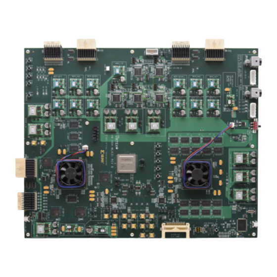
- Page 5 Xilinx ML631 Board Note: Presentation applies to the ML631...
- Page 6 ISE Software Requirements Xilinx ISE 13.3 software Note: Presentation applies to the ML631...
- Page 7 ChipScope Pro Software Requirement Xilinx ChipScope Pro 13.3 software Note: Presentation applies to the ML631...
- Page 8 Setup for the ML631 IBERT Designs...
- Page 9 Setup for the ML631 IBERT Designs Unzip the ML631 IBERT Design Files (13.3 C) to your C:\ drive – Available through http://www.xilinx.com/ml631 Note: Presentation applies to the ML631...
- Page 10 Setup for the ML631 IBERT Designs Important: Set the power switch, SW1, to OFF first The ML631 uses two power supplies; connect both power supplies – Use a power strip to turn on both power supplies simultaneously Only after the two power supplies are on, turn on the power switch...
- Page 11 Setup for the ML631 IBERT Designs When powering down, turn the power switch off, then turn off the power strip – Always follow this sequence when cycling power to the ML631 Leave the power off for now...
- Page 12 Setup for the ML631 IBERT Designs ATX power supplies can be used in lieu of standard power supplies The +12 V on each supply must be capable of supplying 15 A...
- Page 13 Setup for the ML631 IBERT Designs Connect J118 and J120 to pins 2-3 (1) – This selects SMAs J124 and J125 as the clock for the 3 U1 GTH input clocks Connect J121 and J123 to pins 2-3 (1) –...
- Page 14 Setup for the ML631 IBERT Designs HTG AirMax Loopback Rev 2.0 boards (3 each) – Part number: HTG-AIRMAX-LOOPBACK – Connect X2 to X1 and X4 to X3 Note: Presentation applies to the ML631...
- Page 15 Setup for the ML631 IBERT Designs Connect a USB Type-A to Mini-B cable to the USB JTAG connector on the ML631 board – Connect this cable to your PC Note: Presentation applies to the ML631...
- Page 16 Setup for the ML631 IBERT Designs SMA Cables – www.flrst.com – P/N: ASPI-024-ASPI-S402 Note: Presentation applies to the ML631...
- Page 17 GTX Clock Setup...
- Page 18 GTX Clock Setup Turn board power off Connect J117 and J14 to pins “U1” (1) – This selects U1 as the IIC master Note: Presentation applies to the ML631...
- Page 19 GTX Clock Setup Attach AirMax Loopback connectors and SMA GTX Clock – Connect AirMax to P4-J4 Note: Presentation applies to the ML631...
- Page 20 GTX Clock Setup Attach AirMax Loopback connectors and SMA GTX Clock – Connect SMA J134 to J9 – Connect SMA J135 to J10 Note: Presentation applies to the ML631...
- Page 21 GTX Clock Setup Attach AirMax Loopback connectors – Connect AirMax to P1-J1 – Connect AirMax to P2-J2 Note: Presentation applies to the ML631...
- Page 22 GTX Clock Setup Set the power switch, SW1, to OFF (1) Turn on the power strip (with the two ML631 power supplies) Turn on the power switch (1)
- Page 23 GTX Clock Setup Open ChipScope Pro and select JTAG Chain -> USB Cable… (1) Verify 12 MHz operation and click OK (2) Note: Presentation applies to the ML631...
- Page 24 GTX Clock Setup Click OK (1) Note: Presentation applies to the ML631...
- Page 25 GTX Clock Setup Select Device → DEV:1 MyDevice1 (XC6VHX565T) → Configure… Select <Design Path>\ready_for_download\u1_clk_test.bit...
- Page 26 GTX Clock Setup Select Device → DEV:2 MyDevice2 (XC6VHX565T) → Configure… Select <Design Path>\ready_for_download\u2_clk_test.bit Note: Presentation applies to the ML631...
- Page 27 GTX Clock Setup Select File → Open Project… Select <Design Path>\ready_for_download\ml631_clk_test.cpj Note: Presentation applies to the ML631...
- Page 28 GTX Clock Setup All clocks except the 200 & 50 MHz clocks should be at 156.25 MHz – As seen here, U1_MGTREFCLK0_114 is at 0 MHz...
- Page 29 GTX Clock Setup Press SW6 to reset the clocks – Avoid hitting the “PROG” Switch Note: Presentation applies to the ML631...
- Page 30 GTX Clock Setup U1_MGTREFCLK0_114 is now at 156.25 – All clocks should appear as seen below...
- Page 31 GTX Clock Setup Select File → New Project...
- Page 32 GTX Clock Setup Press the PROG button on both FPGAs Note: Presentation applies to the ML631...
- Page 33 Click OK in this dialog box after the two FPGAs are blank ChipScope is now ready to accept a new project – Repeat this process after each section to clear out the old project Note: Presentation applies to the ML631...
- Page 34 ML631 GTX 112 Chip to Chip IBERT Design...
- Page 35 ML631 GTX 112 Chip to Chip IBERT Design U1 GTX 112 Chip to Chip IBERT Connections...
- Page 36 ML631 GTX 112 Chip to Chip IBERT Design U2 GTX 112 Chip to Chip IBERT Connections...
- Page 37 ML631 GTX 112 Chip to Chip IBERT Design Select Device → DEV:1 MyDevice1 (XC6VHX565T) → Configure… Select <Design Path>\ready_for_download\ example_ml631_gtx_112_ibert.bit...
- Page 38 ML631 GTX 112 Chip to Chip IBERT Design Select Device → DEV:2 MyDevice2 (XC6VHX565T) → Configure… Select <Design Path>\ready_for_download\ example_ml631_gtx_112_ibert.bit Note: Presentation applies to the ML631...
- Page 39 ML631 GTX 112 Chip to Chip IBERT Design Select File → Open Project… Select <Design Path>\ready_for_download\ml631_gtx_112_c2c.cpj Note: Presentation applies to the ML631...
- Page 40 ML631 GTX AirMax P1J1 12-Lane IBERT Design Click Yes on this Dialog Note: Presentation applies to the ML631...
- Page 41 ML631 GTX AirMax P1J1 12-Lane IBERT Design Click Yes on this Dialog Note: With Chip to Chip IBERT, linking requires correct settings in both FPGAs...
- Page 42 ML631 GTX 112 Chip to Chip IBERT Design The line rate is 6.25 Gbps (1) Note: U1: Bank 100, 101...
- Page 43 ML631 GTX 112 Chip to Chip IBERT Design TX Diff Output Swing = 590 mV TX Pre-Emphasis = 0; TX Post-Emphasis = 0 Note: Best settings may vary from board to board...
- Page 44 ML631 GTX 112 Chip to Chip IBERT Design TX/RX Data Patterns are set to PRBS 31-bit (1) Click BERT Reset buttons (2) Note: Presentation applies to the ML631...
- Page 45 ML631 GTX 112 Chip to Chip IBERT Design View the RX Bit Error Count (1) Note: Presentation applies to the ML631...
- Page 46 ML631 GTX 112 Chip to Chip IBERT Design Select the second IBERT window Note: Presentation applies to the ML631...
- Page 47 ML631 GTX 112 Chip to Chip IBERT Design The line rate is 6.25 Gbps (1) Note: U2: Bank 110, 111...
- Page 48 ML631 GTX 112 Chip to Chip IBERT Design TX Diff Output Swing = 590 mV TX Pre-Emphasis = 0; TX Post-Emphasis = 0 Note: Best settings may vary from board to board...
- Page 49 ML631 GTX 112 Chip to Chip IBERT Design TX/RX Data Patterns are set to PRBS 31-bit (1) Click BERT Reset buttons (2) Note: Presentation applies to the ML631...
- Page 50 ML631 GTX 112 Chip to Chip IBERT Design View the RX Bit Error Count (1) Select File → New Project and press PROG on both FPGAs Note: Presentation applies to the ML631...
- Page 51 ML631 GTX 1x31x41x5 Chip to Chip IBERT Design...
- Page 52 ML631 GTX 1x31x41x5 Chip to Chip IBERT Design U1 GTX 1x31x41x5 Chip to Chip IBERT Connections...
- Page 53 ML631 GTX 1x31x41x5 Chip to Chip IBERT Design U2 GTX 1x31x41x5 Chip to Chip IBERT Connections...
- Page 54 ML631 GTX 1x31x41x5 Chip to Chip IBERT Design Select Device → DEV:1 MyDevice1 (XC6VHX565T) → Configure… Select <Design Path>\ready_for_download\ example_ml631_gtx_103_104_105_ibert.bit...
- Page 55 ML631 GTX 1x31x41x5 Chip to Chip IBERT Design Select Device → DEV:2 MyDevice2 (XC6VHX565T) → Configure… Select <Design Path>\ready_for_download\ example_ml631_gtx_113_114_115_ibert.bit...
- Page 56 ML631 GTX 1x31x41x5 Chip to Chip IBERT Design Select File → Open Project… Select <Design Path>\ready_for_download\ ml631_gtx_1x31x41x5_c2c.cpj Note: Presentation applies to the ML631...
- Page 57 ML631 GTX 1x31x41x5 Chip to Chip IBERT Design Click Yes on this Dialog Note: Presentation applies to the ML631...
- Page 58 ML631 GTX 1x31x41x5 Chip to Chip IBERT Design Click Yes on this Dialog Note: With Chip to Chip IBERT, linking requires correct settings in both FPGAs...
- Page 59 ML631 GTX 1x31x41x5 Chip to Chip IBERT Design The line rate is 6.25 Gbps (1) Note: U1: Bank 102, 103...
- Page 60 ML631 GTX 1x31x41x5 Chip to Chip IBERT Design TX Diff Output Swing = 590 mV TX Pre-Emphasis = 0; TX Post-Emphasis = 0 Note: Best settings may vary from board to board...
- Page 61 ML631 GTX 1x31x41x5 Chip to Chip IBERT Design TX/RX Data Patterns are set to PRBS 31-bit (1) Click BERT Reset buttons (2) Note: Presentation applies to the ML631...
- Page 62 ML631 GTX 1x31x41x5 Chip to Chip IBERT Design View the RX Bit Error Count (1) Note: Presentation applies to the ML631...
- Page 63 ML631 GTX 1x31x41x5 Chip to Chip IBERT Design Select the second IBERT window Note: Presentation applies to the ML631...
- Page 64 ML631 GTX 1x31x41x5 Chip to Chip IBERT Design The line rate is 6.25 Gbps (1) Note: U2: Bank 112, 113...
- Page 65 ML631 GTX 1x31x41x5 Chip to Chip IBERT Design TX Diff Output Swing = 590 mV TX Pre-Emphasis = 0; TX Post-Emphasis = 0 Note: Best settings may vary from board to board...
- Page 66 ML631 GTX 1x31x41x5 Chip to Chip IBERT Design TX/RX Data Patterns are set to PRBS 31-bit (1) Click BERT Reset buttons (2) Note: Presentation applies to the ML631...
- Page 67 ML631 GTX 1x31x41x5 Chip to Chip IBERT Design View the RX Bit Error Count (1) Select File → New Project and press PROG on both FPGAs Note: Presentation applies to the ML631...
- Page 68 References...
- Page 69 References ChipScope Pro – ChipScope Pro Software and Cores User Guide http://www.xilinx.com/support/documentation/sw_manuals/ xilinx13_3/chipscope_pro_sw_cores_ug029.pdf...
- Page 70 Documentation...
- Page 71 Documentation Virtex-6 – Virtex-6 HXT FPGAs http://www.xilinx.com/products/silicon-devices/fpga/virtex-6/hxt.htm ML631 Documentation – Virtex-6 HXT FPGA Packet Processing/Traffic Management (PP/TM) Kit http://www.xilinx.com/products/boards-and-kits/EK-V6-ML631-G.htm – ML631 Hardware User Guide http://www.xilinx.com/support/documentation/boards_and_kits/ug841.pdf...
Need help?
Do you have a question about the ML631 and is the answer not in the manual?
Questions and answers