ST STM8S User Manual
Touch sensing evaluation board
Hide thumbs
Also See for STM8S:
- Reference manual (449 pages) ,
- Application note (42 pages) ,
- Getting started (40 pages)
Table of Contents
Advertisement
Quick Links
UM0671
User manual
STM8/128-EV/TS
STM8S touch sensing evaluation board
Introduction
The STM8S touch sensing evaluation kit (STM8/128-EV/TS) provides a platform that
introduces users to STMicroelectronics capacitive touch sensing firmware library.
The kit contains an STM8S touch sensing (TS) evaluation daughterboard (STM8Sxxx-TS1)
in addition to the STM8/128-EVAL board.
The STM8S touch sensing evaluation daughterboard provides an evaluation platform for
resistor-capacitor (RC) touch sensing technology for an implementation using 5 keys and
one slider.
The STM8S TS evaluation kit provides a software solution for transforming any 8-bit STM8
microcontroller (MCU) into a capacitive touchkey controller.
For further details about the touch sensing software library, please read the technical
documentation available on www.st.com/touch-sense-sw-lib.
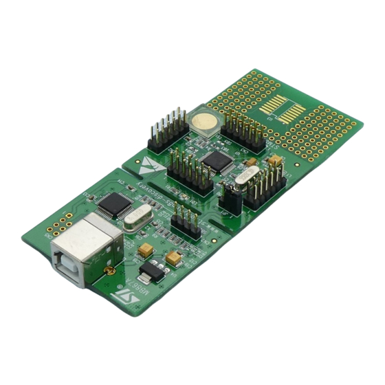
Figure 1.
STM8S touch sensing evaluation kit
February 2010
Doc ID 15330 Rev 4
1/23
www.st.com
Arrow.com.
Downloaded from
Advertisement
Table of Contents

Related Manuals for ST STM8S


Summary of Contents for ST STM8S
- Page 1 (RC) touch sensing technology for an implementation using 5 keys and one slider. The STM8S TS evaluation kit provides a software solution for transforming any 8-bit STM8 microcontroller (MCU) into a capacitive touchkey controller. For further details about the touch sensing software library, please read the technical documentation available on www.st.com/touch-sense-sw-lib.
-
Page 2: Table Of Contents
Evaluation kit board settings ........7 STM8S touch sensing daughterboard ......7 3.1.1... -
Page 3: Overview
USB debugging and programming tools: Raisonance RLink debugger/programmer for ST microcontrollers STice in-circuit emulation system ST MCU Toolset with ST Visual Develop (STVD) IDE and ST Visual Programmer (STVP) programming interface Doc ID 15330 Rev 4 3/23 Arrow.com. -
Page 4: Getting Started With The Touch Sensing Evaluation Kit
AC/DC power supply and its AC adaptors MCU selection guide User manual (this document) IMPORTANT: The STM8 TS library, STM8 Toolset, STM8S firmware library and related documentation are available at www.st.com/touch-sense-sw-lib Using the evaluation kit After connecting the motherboard to the mains supply, the evaluation kit is ready for use. -
Page 5: User Interface
Scroll right De-bounce Filter Enter sub-menu Low Power Mode Parameter 128 mSec setting sub-menus DES Setting Disable STM8S Touch Eval Vx.x.x **Menu** **Menu** **Menu** Sel Key Select Key X Select slider summary STATE Key X Noise rejection Slider STATE K1 K2 K3 K4 K5... - Page 6 Getting started with the touch sensing evaluation kit UM0671 Display options Use the joystick to navigate through the sub-menus as shown in Figure 3 to do the following: Display the state of keys (K1, K2, K3, K4 and K5) and slider on the same screen. Display only the state of the selected key (Kx) (Idle or Detected).
-
Page 7: Evaluation Kit Board Settings
STM8S MCU SWIM measurement connector and jumper STM8S MCU This board uses a STM8S microcontroller (STM8S207K6T6C) in a 32-pin LQFP package. Keys The 5 touchkeys (electrodes) are made of a simple copper surface. Doc ID 15330 Rev 4 7/23 Arrow.com. -
Page 8: Dielectric
In the event of I C communication, the daughterboard provides a connector (J6) for the I data and clock signals for interfacing with the STM8S microcontroller. SWIM connector and setting jumper A single-wire interface module (SWIM) interface (J5) with its associated jumper (W1) for analysis and development. - Page 9 UM0671 Evaluation kit board settings Table 1. Daughterboard MCU pin description (continued) Pin no. Pin name Application usage Option Configuration VCAP VDDIO_1 Load VDDA VSSA LED2 I²C SDA LED3 I²C SCL Joy Down Joy Left Joy Right Joy Up LCD CS Key K1 Key K2 Key K3...
- Page 10 Evaluation kit board settings UM0671 Table 2. Daughter/motherboard CN1 and CN5 header connections Motherboard connector Daughterboard connector (STM8/128-EVAL board) (STM8S2Kxxx-TS1) CN1 header J1 header 11 12 11 12 13 14 13 14 15 16 15 16 17 18 17 18 19 20 19 20 21 22...
-
Page 11: Daughterboard Power Supply
W1 jumper description Configuration Description Uses STM8S TS daughterboard SWIM connector (default setting) Connect PD1of STM8S TS daughterboard device to resource of STM8S/128- EVAL board. For more information, please refer to user manual UM0470: STM8 SWIM communication protocol and debug module. -
Page 12: Analysis Connectors (J2 And J3)
Evaluation kit board settings UM0671 3.1.5 Analysis connectors (J2 and J3) Application designers can use connectors J2 and J3 to analyze electrode and driven shield signals on the daughterboard. Note: The user should take into account possible probe capacitance disturbance and should consider re-calibrating the device before use. -
Page 13: Stm8S2Xx Evaluation Motherboard Settings
Power supply Reset Joystick When using the STM8S TS daughterboard assembled with the STM8/128-EVAL (mother) board, the following settings must be implemented: To maintain STM8S TS daughterboard MCU functionality, the Reset Source (JP1) jumper must be set to the “STice” position (Table 8) on the STM8/128-EVAL board. - Page 14 Evaluation kit board settings UM0671 Table 8. STM8/128-EVAL board settings Jumper Description Configuration Set to “STice” to keep motherboard MCU Reset pin low to enable correct TS daughterboard MCU functionality. (Default configuration) Connect both PSU and DTB jumpers to supply power supply the TS daughterboard.
-
Page 15: Advanced Evaluation Using A Debugging Environment
For further information about ST software, STM8 microcontrollers or debugging tools, please read the associated documentation or ask your local ST support team for a training session. More information is available at www.st.com/touch-sense-sw-lib... - Page 16 SWIM connector SWIM/STM8 adaptor Power supply RLink USB adaptor Download the STM8 touch sensing library from www.st.com/touch-sense-sw-lib Launch the ST Visual Develop (STVD) integrated development environment. Load the STM8 TS evaluation firmware (Figure 10): – In the “File” menu, click “Open workspace” and select/open the file STM8S20xK_TS1_EVAL_FW.stw.
- Page 17 UM0671 Advanced evaluation using a debugging environment Figure 10. Loading the TS evaluation firmware In the “Project” menu, select “Setting” to define the C cosmic location directory (Figure 11). Figure 11. Project settings 10. Build the project by compiling and linking all the source code. In the “Build”...
- Page 18 Advanced evaluation using a debugging environment UM0671 Figure 12. Building the project 11. Select RLink as the debugging tool. – In the “Debug instrument” menu, click “Target setting” and select “SWIM RLink” as shown in Figure Figure 13. Debug instrument settings 12.
- Page 19 UM0671 Advanced evaluation using a debugging environment Figure 14. Debug mode Doc ID 15330 Rev 4 19/23 Arrow.com. Arrow.com. Arrow.com. Arrow.com. Arrow.com. Arrow.com. Arrow.com. Arrow.com. Arrow.com. Arrow.com. Arrow.com. Arrow.com. Arrow.com. Arrow.com. Arrow.com. Arrow.com. Arrow.com. Arrow.com. Arrow.com. Downloaded from Downloaded from Downloaded from Downloaded from Downloaded from...
-
Page 20: Exploring Key Structures
Advanced evaluation using a debugging environment UM0671 Exploring key structures All key and slider data structures can be monitored through the STVD watch window. The main “touch sensing” structures are “sSCKeyInfo” and “sMCKeyInfo”. To learn more about library variables and function descriptions, please refer to the CHM file available at <installation path>\STM8_TS_LIB\stm8_tsl_um.chm Figure 15. -
Page 21: Appendix A Stm8Sxxx-Ts1 Daughterboard Schematics
Appendix A STM8Sxxx-TS1 daughterboard schematics Figure 16. STM8Sxxx-TS1 daughterboard schematic diagram VDD_MCU 0R_0603/DNF 100nF_X7R_0603 Vout JUMPER 100nF_X7R_0603 1µF_X5R_0603 2.2µF_X5R_0603 LP2980ABM3-TR 680nF_X5R_0603 STM8S208K3T 10K_1%_0603 PD7/TLI 11 12 10nF_X7R_0603 0R_0603 13 14 PD6/LINUART_RX 15 16 0R_0603 17 18 PA1/OSCIN PD5/LINUART_TX 19 20 21 22 PA2/OSCOUT PD4/TIM2_CC1/BEEP... -
Page 22: Revision History
Initial release. Updated Figure 3: Navigation scheme on page 5 Display options 09-Mar-2009 on page Corrected reference to STM8S touch sensing evaluation kit from 20-Mar-2009 “STM8/128-EVAL/TS” to “STM8/128-EV/TS”. 26-Feb-2010 Updated values of C3 and C9 in Figure 16 on page... - Page 23 No license, express or implied, by estoppel or otherwise, to any intellectual property rights is granted under this document. If any part of this document refers to any third party products or services it shall not be deemed a license grant by ST for the use of such third party products or services, or any intellectual property contained therein or considered as a warranty covering the use in any manner whatsoever of such third party products or services or any intellectual property contained therein.
Need help?
Do you have a question about the STM8S and is the answer not in the manual?
Questions and answers