Table of Contents
Advertisement
Quick Links
Introduction
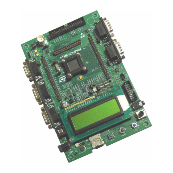
The STM8S2xx evaluation board STM8/128-
EVAL is designed as a complete development
platform for STMicroelectronic's STM8 core-
based STM8S2xx microcontroller with
CAN2.0A/B compliant interface, I
UART channels with smartcard, IrDA and LIN
support, internal 2 Kbyte data Flash and
128 Kbyte code Flash, SWIM debugging support.
The full range of hardware features on the board
is able to help you evaluate all peripherals
(including motor control, CAN, MicroSD card,
smartcard, UART, LIN, IrDA) and develop your
own applications. Extension headers make it
possible to easily connect a daughter board or
wrapping board for your specific application.
Features
■
Two 5 V power supply options: power jack or
daughter board
■
Audio play and record
■
64 or 128 Mbyte MicroSD card
■
Both A&B type smartcard support
■
64 Kbit I
■
2 channels of RS-232 communication
■
IrDA transceiver
■
2 channels of LIN communication
■
CAN2.0A/B compliant connection
■
Inductor motor control connector
■
SWIM and STice debug support
■
122x32 dot-matrix serial interface LCD module
■
Joystick with 4-direction control and selector
■
Reset, Wakeup, Tamper and User button
■
4 LEDs
■
Extension connector for daughter board or
wrapping board.
August 2008
Arrow.com.
Downloaded from
2
C, SPI, two
2
C EEPROM
Figure 1.
STM8/128-EVAL evaluation board
Rev 2
UM0482
User manual
STM8/128-EVAL
evaluation board
1/41
www.st.com
41
Advertisement
Table of Contents

Related Manuals for ST STM8/128-EVAL


Summary of Contents for ST STM8/128-EVAL
- Page 1 UM0482 User manual STM8/128-EVAL evaluation board Introduction Figure 1. STM8/128-EVAL evaluation board The STM8S2xx evaluation board STM8/128- EVAL is designed as a complete development platform for STMicroelectronic's STM8 core- based STM8S2xx microcontroller with CAN2.0A/B compliant interface, I C, SPI, two...
-
Page 2: Table Of Contents
Contents UM0482 Contents Hardware layout and configuration ......4 Power supply ..........7 Clock source . - Page 3 Schematics ..........24 Appendix A STM8/128-EVAL IO assignment ......37 Revision history .
-
Page 4: Hardware Layout And Configuration
Hardware layout and configuration UM0482 Hardware layout and configuration The STM8/128-EVAL evaluation board is designed around the STM8S2xx microcontroller in an 80-pin TQFP package. The hardware block diagram Figure 2 illustrates the connection between STM8S2xx and peripherals (LCD, I C EEPROM, UART, IrDA, LIN, Audio, CAN... - Page 5 UM0482 Hardware layout and configuration Figure 3. STM8/128-EVAL evaluation board top layout CN5, CN1 CN10 Extension header Motor control BNC connector IrDA CN11 LIN1 connector STM8S2xx CN14 LIN2 connector CN13 USART1 SWIM CN15 USART2 Dot-matrix resistor CN16 connector 5V power...
- Page 6 Hardware layout and configuration UM0482 Figure 4. STM8/128-EVAL evaluation board bottom layout CN12 smartcard 6/41 Arrow.com. Downloaded from...
-
Page 7: Power Supply
Hardware layout and configuration Power supply The STM8/128-EVAL evaluation board is designed to be powered by 5 V DC power supply and to be protected by the PolyZen (auto rearmable fuse) U2 from wrong power plug-in event. It is possible to configure the evaluation board to use any of following sources for the power supply. -
Page 8: Reset Source
Hardware layout and configuration UM0482 Reset source The reset signal of STM8/128-EVAL evaluation board is low active and the reset sources include: ● Reset button B1 ● Debugging Tools from connector CN4 ● Daughter board from CN5 The reset pin PA0 of STM8S2XX is connected either to Reset button B1 or to GND by... -
Page 9: C Eeprom
Two D-type 9-pin connectors CN13 (UART1) and CN15 (UART3) are available on the STM8/128-EVAL evaluation board. The USART1 connector is connected to channel 3 of the multiplexer U17, while the USART2 connector is connected to channel 1 of the multiplexer U18. -
Page 10: Motor Control
This is the default setting. Motor control The STM8/128-EVAL evaluation board supports inductor motor control via a 34-pin connector CN10, which provides all required control and feedback signals to and from the motor power-driving board. Available signals on this connector include emergency stop,... -
Page 11: Smartcard
Figure 3 on page 1.10 Smartcard STMicroelectronics smartcard interface chip ST8024 is used on STM8/128-EVAL board for asynchronous 3V and 5V smartcards. It performs all supply protection and control functions based on the connections with STM8S2XX listed in Table Table 8. -
Page 12: Irda
Default status: fitted. 1.14 Development and debug support The debug connectors available on the STM8/128-EVAL evaluation board are: ● CN2, 120-pin SAMTEC connector that supports STice, the advanced emulation system from STMicroelectronics. The JP1 jumper must connect pin 2 together with pin 3 when... -
Page 13: Connectors
UM0482 Connectors Connectors STice connector CN2 Figure 5. STice debugging connector CN2 (top view) Table 11. STice debugging connector (CN2) pin description Pin number Description Pin number Description VCAP 5V VDDA 13/41 Arrow.com. Downloaded from... -
Page 14: Analog Input Connector Cn3
Connectors UM0482 Table 11. STice debugging connector (CN2) pin description (continued) Pin number Description Pin number Description 85-120 Analog input connector CN3 Figure 6. Analog input connector CN3 (bottom view) Table 12. Analog input connector CN3 pin description Pin number Description Pin number Description... -
Page 15: Swim Connectors Cn4 And Cn17
Pin number Description PA0 (RESET) Power connector CN6 Your STM8/128-EVAL evaluation board can be powered from a DC 5V power supply via the external power supply jack (CN6) shown in Figure 8. The central pin of CN6 must be positive. -
Page 16: Can D-Type 9-Pin Male Connector Cn8
Connectors UM0482 CAN D-type 9-pin male connector CN8 Figure 9. CAN D-type 9-pins male connector CN8 (front view) Table 14. CAN D-type 9-pins male connector CN8 pin description Pin number Description Pin number Description 1,4,8,9 CANH CANL 3,5,6 MicroSD connector CN9 Figure 10. -
Page 17: Motor Control Connector Cn10
UM0482 Connectors Motor control connector CN10 Figure 11. Motor control connector CN10 (top view) 33 31 29 27 25 23 21 19 17 15 13 11 9 7 5 34 32 30 28 26 24 22 20 18 16 14 12 10 8 6 Table 16. -
Page 18: Lin Connectors Cn11 And Cn14
Connectors UM0482 LIN connectors CN11 and CN14 Figure 12. LIN connector CN11 (LIN1) and CN14 (LIN2) front view Table 17. LIN connector CN11 (LIN1) and CN14 (LIN2) pin connection Pin number Description Pin number Description LIN wire Battery power input 2.10 Smartcard connector CN12 Figure 13. -
Page 19: Rs-232 Connectors Cn13 And Cn15
UM0482 Connectors 2.11 RS-232 connectors CN13 and CN15 Figure 14. RS-232 connectors CN13 and CN15 (top view) Table 19. RS-232 connector CN13 and CN15 pin description Pin number Description Pin number Description Connect to Pin 4 USART_RXD Connect to Pin 8 USART_TXD Connect to Pin 7 Connect to Pin 6... -
Page 20: Daughter Board Extension Connectors Cn1 And Cn5
Two 50-pin male headers CN1 and CN5 can be used to connect a daughter board or standard wrapping board to the STM8/128-EVAL evaluation board. All GPI/Os are available on it. The space between the two connectors and the position of the power, GND and... - Page 21 UM0482 Connectors Table 21. Daughter board extension connector CN1 (continued) Description Alternative function How to disconnect function block on STM8/128-EVAL board Dip-Switch 7 Keep S2 OFF and remove R102. SmartCard_OFF Remove R76. I2C EEPROM Remove R96. MicroSDCard Detect Remove R101.
- Page 22 Connectors UM0482 Table 22. Daughter board extension connector CN5 Description Alternative function How to disconnect component on STM8/128-EVAL board SWIM MC connector pin31 Keep JP9 on open, remove R75. UART3_TX Remove R91. JOY_Select Remove R39. PA0/RESET RESET# button PA0 available on pin 12.
- Page 23 UM0482 Connectors Table 22. Daughter board extension connector CN5 (continued) Description Alternative function How to disconnect component on STM8/128-EVAL board OSCIN Remove X1 from socket. Disconnect STM8/128-EVAL evaluation board from motor power MC connector pin34 drive board. UART1_TX Remove R90.
- Page 24 Schematics UM0482 Schematics This section provides the design schematics for the STM8/128-EVAL board key features, to help you implement these features in your applications. Schematics are provided for: ● Microcontroller connections, see Figure 16 ● MCU, see Figure 17 ●...
- Page 25 UM0482 Schematics Figure 16. Microcontroller connections 25/41 Arrow.com. Downloaded from...
- Page 26 Schematics UM0482 Figure 17. MCU 26/41 Arrow.com. Downloaded from...
- Page 27 UM0482 Schematics Figure 18. LCD, joystick, CAN and I C EEPROM connections 27/41 Arrow.com. Downloaded from...
- Page 28 Schematics UM0482 Figure 19. Multiplexer 28/41 Arrow.com. Downloaded from...
- Page 29 UM0482 Schematics Figure 20. Audio peripherals 29/41 Arrow.com. Downloaded from...
- Page 30 Schematics UM0482 Figure 21. Motor control 30/41 Arrow.com. Downloaded from...
- Page 31 UM0482 Schematics Figure 22. STice connector and extension connectors 31/41 Arrow.com. Downloaded from...
- Page 32 Schematics UM0482 Figure 23. QST connector 32/41 Arrow.com. Downloaded from...
- Page 33 UM0482 Schematics Figure 24. LIN connectors 33/41 Arrow.com. Downloaded from...
- Page 34 Schematics UM0482 Figure 25. UART and IrDA connectors 34/41 Arrow.com. Downloaded from...
- Page 35 UM0482 Schematics Figure 26. Smartcard connections 35/41 Arrow.com. Downloaded from...
- Page 36 Schematics UM0482 Figure 27. Power supply 36/41 Arrow.com. Downloaded from...
- Page 37 UM0482 STM8/128-EVAL IO assignment Appendix A STM8/128-EVAL IO assignment Table 23. STM8/128-EVAL pin functions Pin name Main Alternate function STM8/128-EVAL pin assignment NRST / RESET NRST RESET RESET PA1 / OSCIN OSCIN OSCIN PA2 / OSCOUT OSCOUT OSCOUT VSSIO / VSSIO_1...
- Page 38 STM8/128-EVAL IO assignment UM0482 Table 23. STM8/128-EVAL pin functions (continued) Pin name Main Alternate function STM8/128-EVAL pin assignment PB1 / AIN1 AIN1 MC_pin17/ Current phase B PB0 / AIN0 AIN0 MC_pin19 / Current phase C PH4 / TIM1_ETR TIM1_ETR LCD backlight control...
- Page 39 UM0482 STM8/128-EVAL IO assignment Table 23. STM8/128-EVAL pin functions (continued) Pin name Main Alternate function STM8/128-EVAL pin assignment PE2 / I2C_SDA I2C_SDA I2C_SDA / EEPROM / QST_pin5 PE1 / I2C_SCL I2C_SCL I2C_SCLK / EEPROM / QST_pin3 PE0 / MCO Smartcard_OFF...
- Page 40 22: changed alternate function for pins 7, 8, 15, 17, and 18. Table 23: changed pin name and alternate function for pins 9, 10,11,12,36-38,43-46, 75, 76, 77, 78,79. Modified STM8/128-EVAL pin assignment for pins 10, 11,12, 78, and 79. 40/41 Arrow.com.
- Page 41 No license, express or implied, by estoppel or otherwise, to any intellectual property rights is granted under this document. If any part of this document refers to any third party products or services it shall not be deemed a license grant by ST for the use of such third party products or services, or any intellectual property contained therein or considered as a warranty covering the use in any manner whatsoever of such third party products or services or any intellectual property contained therein.
Need help?
Do you have a question about the STM8/128-EVAL and is the answer not in the manual?
Questions and answers