Nucleo-32 open development platform with a wide choice of specialized shields. The STM8 Nucleo-32 board does not require any separate probe as it integrates the ST-LINK/V2-1 debugger/ programmer and comes with the STM8 standard peripheral library, together with various packaged software examples.
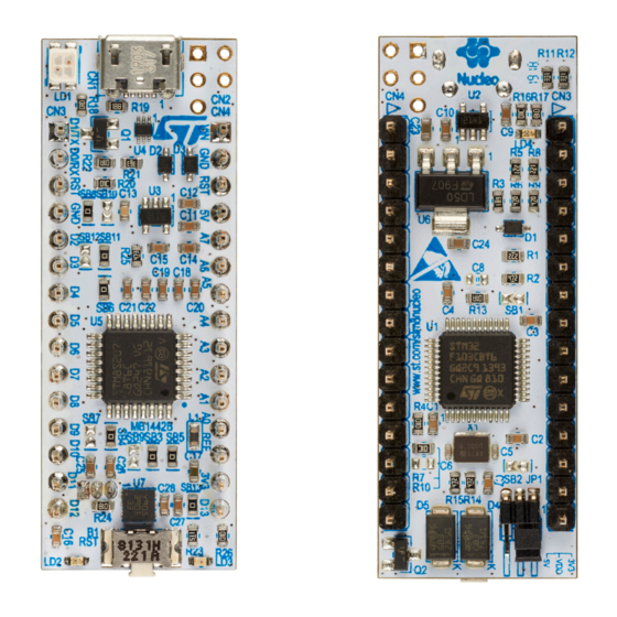
Flexible power-supply options: ST-LINK USB V or external sources (3.3 V, 5 V, 7 V – 12 V) • On-board ST-LINK/V2-1 debugger/programmer with SWIM connector and USB re-enumeration capability: mass storage, Virtual COM port and debug port • Comprehensive free software STM8 libraries including a variety of software examples •...
Evaluation tools marked as “ES” or “E” are not yet qualified and therefore not ready to be used as reference design or in production. Any consequences deriving from such usage will not be at ST charge. In no event, ST will be liable for any customer usage of these engineering sample tools as reference designs or in production.
The demonstration software is preloaded in the STM8 Flash memory for easy demonstration of the device peripherals in standalone mode. The latest versions of the demonstration source code and associated documentation can be downloaded from the demonstration resource section of the STM8 Nucleo board webpage at www.st.com. UM2391 - Rev 1 page 4/25...
UM2391 Conventions Conventions Table 3 provides the conventions used for the ON and OFF settings in the present document. Table 3. ON/OFF convention Convention Definition Jumper JPx ON Jumper fitted Jumper JPx OFF Jumper not fitted Jumper JPx [1-2] Jumper should be fitted between Pin 1 and Pin 2 Solder bridge SBx ON SBx connections closed by 0 Ω...
UM2391 Quick start Quick start NUCLEO-8S207K8 STM8 Nucleo-32 board featuring the STM8S207K8T6C STM8 8-bit MCU provides an affordable and flexible way for users to try out new concepts and build prototypes with an STM8S Series microcontroller in an LQFP32 package.
Hardware layout and configuration The STM8 Nucleo-32 board is designed around an STM8S Series microcontroller in an LQFP32 package. Figure 3 shows the connections between the STM8 and its peripherals (ST-LINK/V2-1, push-button, LED, and ® ARDUINO Nano V3 expansion connector).
ST-LINK SWD connector (reserved) connects 3V3 regulator STM8 pin PD7 to TLI STM8 microcontroller connects VCP RX to ST-LINK connects OSCIN / PA1 to MCO connects VCP TX to ST-LINK Reset button Red LED Power Green LED UM2391 - Rev 1...
6.3.2 ST-LINK/V2-1 firmware upgrade The ST-LINK/V2-1 embeds a firmware mechanism for the in-situ upgrade through the USB port. As the firmware may evolve during the lifetime of the ST-LINK/V2-1 product (for example new functionalities, bug fixes, support for new microcontroller families), it is recommended to visit the www.st.com...
The STM8 Nucleo-32 board and shield board can be powered from the ST-LINK USB connector CN1. Note that only the ST-LINK part is power supplied before the USB enumeration phase, as the host PC only provides 100 mA to the boards at that time. During the USB enumeration, the STM8 Nucleo-32 board requires 300 mA of current to the host PC.
Using the 3V3 (CN4 pin 14) directly as power input can be interesting, for instance, in case the 3.3 V is provided by a shield board. In this case, the ST-LINK is not powered, thus programming and debugging features are not available.
Thanks to SB3 and SB4, the UART interface of STM8 available on PD5 (TX) and PD6 (RX), can be connected to ® ST-LINK/V2-1. When UART Virtual communication is not used it is possible to use PD5/PD6 on ARDUINO pins D1/D0. Refer to Table Table 6.
PA2 and PA3 on STM32F103CBT6 (ST-LINK MCU) are disconnected from respectively PD5 and PD6 on STM8. PD5 and PD6 can be used as GPIO on Arduino connector CN4. MCO on STM32F103CBT6 (ST-LINK MCU) is connected to PA1 on STM8. MCO on STM32F103CBT6 (ST-LINK MCU) is disconnected from PA1 on STM8.
Nano can fit the STM8 Nucleo-32 board Caution: ® The STM8 I/Os are 3.3 V compatible instead of 5 V for ARDUINO Nano. ® Figure 8. ARDUINO Nano connectors NUCLEO-8S207K8 NRST RESET RESET NRST PD7 || PF4 PF4 || PD7 PE5 / PD4 AREF...
SPI clock 1. SB not fitted 2. In order not to have any conflict on the VCP signals (PD5 and PD6) when SB7 and SB9 are ON, SB3 and SB4 of ST-LINK must be OFF. Conversely for the other case.
UM2391 Federal Communications Commission (FCC) and Industry Canada (IC) Compliance Statements Federal Communications Commission (FCC) and Industry Canada (IC) Compliance Statements FCC Compliance Statement Part 15.19 This device complies with Part 15 of the FCC Rules. Operation is subject to the following two conditions: (1) this device may not cause harmful interference, and (2) this device must accept any interference received, including interference that may cause undesired operation.
UM2391 CE conformity CE conformity Warning EN 55032 / CISPR32 (2012) Class A product Warning: this device is compliant with Class A of EN55032 / CISPR32. In a residential environment, this equipment may cause radio interference. Avertissement : cet équipement est conforme à la Classe A de la EN55032 / CISPR 32. Dans un environnement résidentiel, cet équipement peut créer des interférences radio.
Page 25
ST’s terms and conditions of sale in place at the time of order acknowledgement. Purchasers are solely responsible for the choice, selection, and use of ST products and ST assumes no liability for application assistance or the design of Purchasers’...
Need help?
Do you have a question about the NUCLEO-8S207K8 and is the answer not in the manual?
Questions and answers