Table of Contents
Advertisement
Quick Links
UM0684
User manual
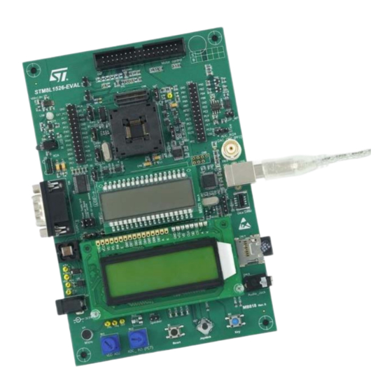
STM8L1526-EVAL evaluation board
Introduction
The STM8L1526-EVAL evaluation board is a complete demonstration and development
platform for STMicroelectronic's STM8 core-based STM8L152C6 microcontroller which
supports I2C, SPI, USART, 12-bit ADC, 12-bit DAC, LCD driver, 2 KB internal SRAM, 32 KB
EEPROM and SWIM debugging.
The full range of hardware features on the board helps you evaluate all peripherals (motor
control, USART, audio DAC, LCD, IR LED, IrDA, SPI Flash, MicroSD Card, temperature
sensor and EEPROM... etc.) and develop your own applications. Extension headers
facilitate easy connection of a daughterboard or wrapping board for specific applications.
An ST-LINK is integrated on the board as the embedded in-circuit debugger and
programmer for the STM8 MCU.
Figure 1.
STM8L1526-EVAL evaluation board
September 2009
Doc ID 15437 Rev 1
1/46
www.st.com
Downloaded from
Elcodis.com
electronic components distributor
Advertisement
Table of Contents

Related Manuals for ST STM8L1526-EVAL


Summary of Contents for ST STM8L1526-EVAL
- Page 1 EEPROM… etc.) and develop your own applications. Extension headers facilitate easy connection of a daughterboard or wrapping board for specific applications. An ST-LINK is integrated on the board as the embedded in-circuit debugger and programmer for the STM8 MCU.
-
Page 2: Table Of Contents
Contents STM8L1526-EVAL Contents Features ........... 4 Hardware . - Page 3 Schematics ..........29 Appendix A STM8L1526-EVAL I/O assignment ......43 Revision history .
-
Page 4: Features
STM8L1526-EVAL Features Hardware Three 5 V power supply options: power jack, ST-LINK USB connector or daughterboard Audio speaker and microphone connected to the DAC and ADC of the STM8L152C6 1 GByte SPI interface MicroSD Card 128 Mbit SPI serial Flash... -
Page 5: Hardware Layout And Configuration
LQFP package). The hardware block diagram Figure 2 illustrates the connection between the STM8L152C6 and the peripherals (LCD glass, dot matrix LCD, serial Flash, EEPROM, temperature sensor, USART, IrDA, audio, MicroSD Card, Motor control and embedded ST- LINK). Figure 3 Figure 4 help you locate these features on the actual evaluation board. - Page 6 Hardware layout and configuration STM8L1526-EVAL Figure 3. STM8L1526-EVAL layout CN4, CN10 Extension header CN7 Motor control STM8L1526 CN8 STice connector LD6 IR LED glass module U2 IrDA CN15 BNC connector CN11 ST-LINK USART USB connector CN12 & CN13 SWIM connector...
- Page 7 STM8L1526-EVAL Hardware layout and configuration Figure 4. STM8L1526-EVAL jumpers and solder bridges Doc ID 15437 Rev 1 7/46 Downloaded from Elcodis.com electronic components distributor...
-
Page 8: Power Supply
STM8L1526-EVAL Power supply The STM8L1526-EVAL is designed to be powered by a 5 V DC power supply and to be protected by PolyZen from a wrong power plug-in event. It is possible to configure the evaluation board to use any of following three power supply sources. -
Page 9: Clock Source
Section 2.4: LCD glass module for details. The LED LD8 is lit when the STM8L1526-EVAL evaluation board is powered by the 5 V correctly, the LED LD9 is lit if the MCU is powered by a low voltage (VDD < 1.8 V). -
Page 10: Reset Source
Hardware layout and configuration STM8L1526-EVAL Reset source The reset signal of the STM8L1526-EVAL is low active and the reset sources include: Reset button B1 Debugging tools from SWIM connector CN12 and CN16 Daughterboard from CN10 Embedded ST-LINK RS-232 connector CN1 for ISP Table 4. -
Page 11: Audio
Figure 6. LCD glass module in position LCD Audio The STM8L1526-EVAL supports: a speaker connected to the DAC output of the STM8L152C6 through an audio amplifier which can be enabled or disabled by setting JP9. The choice between BNC or DAC... -
Page 12: Eeprom
Both RS-232 and IrDA communication is supported by D-type 9-pin RS-232 connectors CN1 and IrDA transceiver U2 which connect to the USART of the STM8L152C6 on the STM8L1526-EVAL evaluation board. The signal Bootloader_RESET is added on the RS-232 connector for ISP support. -
Page 13: Motor Control
Hardware layout and configuration Motor control The STM8L1526-EVAL supports three-phase brushless motor control via a 34-pin connector, CN7, which provides all required control and feedback signals to and from motor power-driving board. Available signals on this connector include emergency stop, motor speed, 3 phase motor current, bus voltage, heat sink temperature coming from the motor driving board and 6 channels of PWM control signal going to the motor driving circuit. - Page 14 Hardware layout and configuration STM8L1526-EVAL Figure 7. STM8L1526-EVAL motor control re-configuration of board 14/46 Doc ID 15437 Rev 1 Downloaded from Elcodis.com electronic components distributor...
-
Page 15: Microsd Card
STM8L1526-EVAL Hardware layout and configuration MicroSD Card The 1 GByte MicroSD Card connected to the SPI port of the STM8L152C6 is available on the board. MicroSD Card detection is managed by standard I/O port, PD6. The LCD glass module must be mounted in the IO position for MicroSD Card. Refer to Chapter 2.4: LCD glass module... -
Page 16: Development And Debug Support
STM8L1526-EVAL as the default debugger. Third-party debuggers are also supported by the SWIM connector, CN12, or low-cost SWIM connector, CN16. The SWIM connector or embedded ST-LINK can be enabled by setting jumper JP6. Table 9. SWIM debugging related jumper... -
Page 17: Display And Input Devices
The 4-direction joystick (U17) with selection key and general purpose button (B2) are available as input devices. The STM8L1526-EVAL evaluation board also supports a second optional 2.4" TFT LCD that can be mounted on the CN3 connector. The 2.4" TFT LCD is not populated by default. -
Page 18: Idd Measurement And Comparator
STM8L1526- EVAL. Figure 8. STM8L1526-EVAL IDD measurement circuit In Run mode, IDD current is measured using MAX9938FEUK+ (U20) connected to the 2ohm shunt resistor. In this case IDD_CNT_EN remains at a high level during measurement and the jumper must be connected between pin 1 and pin 2 of JP11. -
Page 19: Comparator
One I/O PE0 used as output, connected to the reference resistor (Rref) used to charge Cref. Comparator inverting input used as ADC input PC7 to be connected to the potentiometer. Figure 10. STM8L1526-EVAL low precision ADC based on comparator COMP2 CMP_Rref COMP2A... -
Page 20: Ir Led
Hardware layout and configuration STM8L1526-EVAL The measurement is performed in three steps: Internal reference voltage VREFINT is connected to the comparator inverting input and Cref to noninverting input to measure the time required to charge the capacitor to internal reference voltage VREFINT by PE0 used as output through Rref. -
Page 21: Connectors
Bootloader_RESET RS232_RX (PC2) RS232_TX (PC3) Power connector CN2 The STM8L1526-EVAL evaluation board can be powered from a DC 5 V power supply via the external power supply jack (CN2) shown in Figure 12. The central pin of CN2 must be positive. -
Page 22: Daughterboard Extension Connector Cn4 And Cn10
Two 26-pin male headers CN4 and CN10 can be used to connect the daughterboard or standard wrapping board to the STM8L1526-EVAL evaluation board. All GPI/Os are available on it. The space between these two connectors and position of power, GND and RESET pin are defined as a standard which allows to develop common daughterboards for several evaluation boards. - Page 23 Connectors Table 14. Daughterboard extension connector CN4 (continued) How to disconnect with function Pin Description Alternative function block on STM8L1526-EVAL board Set SB2 to close 16MHZ crystal Remove X1 and C30 Set SB1 to close 16MHZ crystal Remove X1 and C38...
-
Page 24: Lcd Glass Connector Cn5 And Cn6
UART_IrDA_TX MCU_VDD Note: All I/O's marked in grey can be disconnected with function block on the STM8L1526-EVAL board by removing LCD glass module (MB821) board. LCD glass connector CN5 and CN6 Two 36-pin male headers, CN5 and CN6, can be used to mount the LCD glass module (MB821) on it. -
Page 25: Motor Control Connector Cn7
Encoder Index STice connector CN8 The STice can be connected to emulate the STM8L1526-EVAL board. Jumper JP13 must be set to connect pin 2 and 3 when the STice is connected on CN8. It is used to keep the STM8L152C6 MCU on reset as explained in Section 2.3: Reset... - Page 26 Connectors STM8L1526-EVAL Figure 14. STice debugging connector CN8 viewed from above Table 17. STice debugging connector CN8 Pin number Description Pin number Description RESET# VDD_MCU VDDA VDDA VLCD VDD_MCU 49-60 26/46 Doc ID 15437 Rev 1 Downloaded from Elcodis.com electronic components distributor...
-
Page 27: St-Link Programming Connector Cn9
It is not populated by default and is not intended for the end user. USB type B connector CN11 The USB connector CN11 is used to connect embedded ST-LINK to PC for debugging of board. Figure 15. USB type B connector CN11 viewed from the front Table 18. -
Page 28: Microsd Connector Cn14
Connectors STM8L1526-EVAL 3.12 MicroSD connector CN14 Figure 17. MicroSD connector CN14 viewed from the front Table 20. MicroSD connector CN14 Pin number Description Pin number Description MicroSDcard_CLK (PB5) MicroSDcard_CS (PE3) Vss/GND MicroSDcard_DIN(PB6 MicroSDcard_DOUT(P +3V3 MicroSDcard_detect (PD6) 3.13 BNC connector CN15 Figure 18. -
Page 29: Schematics
STM8L1526-EVAL Schematics Schematics The schematics are shown on the following pages: Table 19: STM8L1526-EVAL on page 30 Table 20: MCU on page 31 Table 21: LCD glass connector on page 32 Table 22: Audio on page 33 Table 23: Peripherals on page 34... - Page 30 Figure 19. STM8L1526-EVAL U_MCU U_EEPROM_TemSensor MCU.SchDoc EEPROM_TemSensor. SCHDOC I2C_SLK I2C_SLK I2C_SMB U_Extension_STice connector I2C_SDA I2C_SDA Extension_STice connector. SCHDOC U_Audio U_RS232_IrDA Audio.SchDoc +3V3 100nF RS232_IrDA.SCHDOC PC[0..7] PC[0..7] 100nF Audio_OUT Audio_OUT Audio_IN VCCA VCCB Bootloader_RESET R32 0 PB[0..7] PB[0..7] RS232/IrDA_RX R37 0 U_LCD_Glass PD[0..7]...
- Page 31 [N/A] AIN- VDD_MCU VDDA close to PF0 of MCU BEAD 100nF 100nF 100nF PA[0..7] PA[0..7] PB[0..7] PB[0..7] STMicroelectronics PC[0..7] PC[0..7] PD[0..7] PD[0..7] PE[0..7] PE[0..7] Title: STM8L1526-EVAL MCU Number: MB818 Rev: C.1(PCB.SCH) Date: 7/31/2009 Sheet Downloaded from Elcodis.com electronic components distributor...
- Page 32 PB4_LCDSEG14 LCD_CS PB1_LCDSEG11 MC_PFCpwm PB0_LCDSEG10 MC_EnA PD0_LCDSEG7 MC_PFCsync1 PE5_LCDSEG6 MC_CurrentB PE2_LCDSEG3 JOY_SEL PE1_LCDSEG2 JOY_LEFT PA4_LCDCOM0 COM1 LED1 PA5_LCDCOM1 COM2 LED2 Header STMicroelectronics Title: STM8L1526-EVAL LCD Glass connector MB818 C.1(PCB.SCH) Date: 7/31/2009 Number: Rev: Sheet Downloaded from Elcodis.com electronic components distributor...
- Page 33 +3V3 470nF Bypass [N/A] TS4990IST +3V3 10uF KECG2740TBL 2.2K MIC_OUT MIC+ TS461CLT Audio_IN 100nF 47pF [N/A] [N/A] 100K 180pF 4.7uF 2.2uF 100K 4.7uF STMicroelectronics Title: STM8L1526-EVAL Audio Number: MB818 Rev: C.1(PCB.SCH) Date: 7/27/2009 Sheet Downloaded from Elcodis.com electronic components distributor...
- Page 34 JOY_LEFT LEFT +3V3 JOY_RIGHT RIGHT solder bridge JOY_UP 1<->2 close by default LM393PT MT008-A IR_LED 1.2K Joystick 9013 9013 STMicroelectronics Title: IR_LED STM8L1526-EVAL Peripherals Low Voltage LED Number: MB818 Rev: C.1(PCB.SCH) Date: 7/28/2009 Sheet Downloaded from Elcodis.com electronic components distributor...
- Page 35 VDD_ADJ 124[1%] IDD_CNT_EN Vout 74LV4060PW 10uF 40.2[1%] Oscillator frequency 30KHz 100nF 3386P-201H[5%] R125 2K2[1%] ZEN056V130A24LS 220uF DC-10B SMAJ5.0A-TR 100nF BNX002-01 Ground STMicroelectronics Header 3X2 Title: STM8L1526-EVAL Power Number: MB818 Rev: C.1(PCB.SCH) Date: 7/27/2009 Sheet Downloaded from Elcodis.com electronic components distributor...
- Page 36 23 24 25 26 Header 13X2 on the right PA[0..7] PA[0..7] PB[0..7] PB[0..7] PC[0..7] PC[0..7] PD[0..7] PD[0..7] STice connector PE[0..7] PE[0..7] Exension connector STMicroelectronics Title: STM8L1526-EVAL Extension&STice Number: MB818 Rev: C.1(PCB.SCH) Date: 7/27/2009 Sheet Downloaded from Elcodis.com electronic components distributor...
- Page 37 2.4" LCD connector (MB542 with AM240320L8TNQW-00H) +3V3 [N/A] [N/A] RESET +3V3 RESET# [N/A] [N/A] [N/A] STMicroelectronics +3V3 BL_VDD BL_Control BL_GND Title: BL_GND STM8L1526-EVAL LCD&SDcard TFT LCD Do not fit Number: MB818 Rev: C.1(PCB.SCH) Date: 7/27/2009 Downloaded from Elcodis.com electronic components distributor...
- Page 38 R2IN R3OUT R3IN RS232/IrDA_RX R4OUT R4IN R5OUT R5IN +3V3 nSHDN ST3241EBPR +3V3 Anode (VCC2) Cathode VCC1 Vlogic TFDU4300 IrDA 4.7uF 4.7uF 100nF 100nF STMicroelectronics Title: STM8L1526-EVAL RS232&IrDA MB818 C.1(PCB.SCH) Date: 7/28/2009 Number: Rev: Sheet Downloaded from Elcodis.com electronic components distributor...
- Page 39 R53 0 Default setting: Open [N/A] [N/A] R76 0 [N/A] MC_PFCsync2 R56 0 Default setting: Open MC_PFCsync1 [N/A] 10nF [N/A] [N/A] [N/A] STMicroelectronics Title: STM8L1526-EVAL Motor Control Number: MB818 Rev: C.1(PCB.SCH) Date: 7/31/2009 Sheet Downloaded from Elcodis.com electronic components distributor...
- Page 40 Figure 29. EEPROM and temperature sensor R115 I2C_SDA R116 I2C_SLK JP14 R119 M24C64-FDW5TP EEPROM 100nF +3V3 R112 R113 R114 BSN20 R120 R118 I2C_SMB OS/INT 100nF STLM75M2E BSN20 Temperature sensor STMicroelectronics Title: STM8L1526-EVAL EEPROM&TemperatureSensor Number: MB818 Rev: C.1(PCB.SCH) Date: 7/27/2009 Downloaded from Elcodis.com electronic components distributor...
- Page 41 R103 ST_LINK_LED +3V3 R102 R106 R109 +3V3 CN11 AIN_1 R107 USB_DM R108 USB_DP 100nF 100nF 100nF 100nF STMicroelectronics SHELL SHELL USB-typeB connector Title: STM8L1526-EVAL ST_LINK (SWIM only) Number: MB818 Rev: C.1(PCB.SCH) Date: 7/28/2009 Sheet Downloaded from Elcodis.com electronic components distributor...
- Page 42 Figure 31. MB821 Header 18 Header 18X2 PD878-DP-FH-W-LV-6-RH Header 18 Header 18X2 STMicroelectronics Title: STM8L2xx EVAL LCD board Number: MB821 Rev: A.1(PCB.SCH) Date: 9/10/2009 Sheet Downloaded from Elcodis.com electronic components distributor...
-
Page 43: Appendix Astm8L1526-Eval I/O Assignment
STM8L1526-EVAL STM8L1526-EVAL I/O assignment Appendix A STM8L1526-EVAL I/O assignment Table 22. STM8L1526-EVAL I/O assignment Pin No. Pin name STM8L1526-EVAL I/O assignment SWIM / IR_LED RESET button 16MHZ crystal 16MHZ crystal LED1 / Motor control connector (Current A) LED2 / Motor control connector (Bus voltage) - Page 44 STM8L1526-EVAL I/O assignment STM8L1526-EVAL Table 22. STM8L1526-EVAL I/O assignment (continued) Pin No. Pin name STM8L1526-EVAL I/O assignment Joystick_down / Motor control connector (MC_VH) Joystick_right / Motor control connector (MC_WH) Motor control connector (EmergencySTOP) / SDcard_detect Joystick_up / Motor control connector (MC_UL) I²C SDA...
-
Page 45: Revision History
STM8L1526-EVAL Revision history Revision history Table 23. Document revision history Date Revision Changes 10-Sep-2009 Initial release. Doc ID 15437 Rev 1 45/46 Downloaded from Elcodis.com electronic components distributor... - Page 46 No license, express or implied, by estoppel or otherwise, to any intellectual property rights is granted under this document. If any part of this document refers to any third party products or services it shall not be deemed a license grant by ST for the use of such third party products or services, or any intellectual property contained therein or considered as a warranty covering the use in any manner whatsoever of such third party products or services or any intellectual property contained therein.
Need help?
Do you have a question about the STM8L1526-EVAL and is the answer not in the manual?
Questions and answers