Table of Contents
Advertisement
Quick Links
SAFETY INFORMATION
Regarding this manual:
• This manual should be turned over to the end user.
• Before use, read this manual thoroughly to comprehend its
contents.
• The contents of this manual may be changed without prior
notice.
• All rights reserved. No part of this manual may be reproduced
in any form without Nailor's written permission.
• Nailor makes no warranty of any kind with regard to this
material, including, but not limited to, implied warranties of
merchantability and suitability for a particular purpose.
• All reasonable effort has been made to ensure the accuracy
of the contents of this manual. However, if any errors are
found, please inform Nailor.
• Nailor assumes no responsibilities for this product except
as stated in the warranty. If the customer or any third party
is harmed by the use of this product, Nailor assumes no
responsibility for any such harm owing to any defects in the
product which were not predictable, or for any indirect damages.
3/21 IOM-ELECTRA-FLO-INST
Nailor Industries Inc. reserves the right to change any information concerning product or specification without notice or obligation.
OPERATION AND MAINTENANCE MANUAL
THERMAL AIRFLOW & TEMPERATURE MEASUREMENT
SYSTEM • ELECTRA-FLO G5 AIRFLOW TRANSMITTER
FOR MODELS AMD-TD-10 & AMD-TD-20
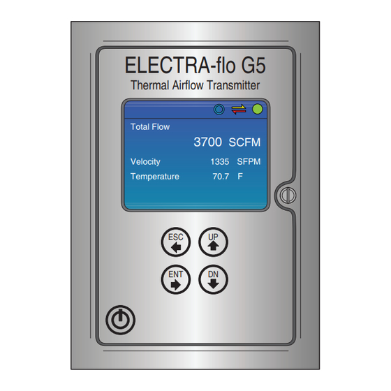
ELECTRA-flo G5
Thermal Airflow Transmitter
Total Flow
3700
SCFM
Velocity
1335
Temperature
70.7
ESC
UP
ENT
DN
Safety Precautions:
The following general safety precautions must be observed
during all phases of installation, operation, service, and repair
of this product. Failure to comply with these precautions or
with specific warnings given elsewhere in this manual violates
safety standards of design, manufacture, and intended use of
the product. Nailor Industries Inc. assumes no liability for the
customer's failure to comply with these requirements. If this
product is used in a manner not specified in this manual, the
protection provided by this product may be impaired.
The following messages are used in this manual.
Caution:
Messages identified as "Caution" contain information regarding
potential damage to the product or other ancillary products.
Important Note:
Messages identified as "Important Note" contain information
critical to the proper operation of the product.
SFPM
F
Page 1
Advertisement
Table of Contents

Summary of Contents for Nailor ELECTRA-FLO G5
- Page 1 3/21 IOM-ELECTRA-FLO-INST Page 1 Nailor Industries Inc. reserves the right to change any information concerning product or specification without notice or obligation.
-
Page 2: Table Of Contents
Service Menu ................................29 - 30 SECTION 4.0 MAINTENANCE, INSPECTIONS, TROUBLESHOOTING ................. 31 Maintenance / Inspections ..............................31 Troubleshooting .................................. 31 Page 2 3/21 IOM-ELECTRA-FLO-INST Nailor Industries Inc. reserves the right to change any information concerning product or specification without notice or obligation. -
Page 3: Section 1.0 General Information
PROBE ARRAY CABLE WITH MINI-DIN CONDUIT SNAP AND LOCK CONNECTION CONNECTOR OUTPUT SIGNALS Typical Airflow G5 Transmitter and Probe Installation 3/21 IOM-ELECTRA-FLO-INST Page 3 Nailor Industries Inc. reserves the right to change any information concerning product or specification without notice or obligation. -
Page 4: Standard Features And Specifications
Maximum of 32 sensors per transmitter, shared between both channels Sensor Capacity Probe Maximum of 8 sensors per probe Page 4 3/21 IOM-ELECTRA-FLO-INST Nailor Industries Inc. reserves the right to change any information concerning product or specification without notice or obligation. - Page 5 • Aluminum honeycomb airflow straightening cell NOTE: Field characterization required to achieve ±3% system accuracy. * SPECIFICATIONS subject to change without notice. 3/21 IOM-ELECTRA-FLO-INST Page 5 Nailor Industries Inc. reserves the right to change any information concerning product or specification without notice or obligation.
-
Page 6: Checking That You Received Everything
Review this information and verify that the set-up is correct for your application. If any problems or discrepancies are detected, contact Nailor’s Application Engineering Department prior to proceeding. Page 6 3/21 IOM-ELECTRA-FLO-INST Nailor Industries Inc. reserves the right to change any information concerning product or specification without notice or obligation. -
Page 7: Transmitter Dimensions
5. Two (2) 1/2" NPT liquid tight cord grips. 3. Two (2) Mini-DIN connectors for probe. 6. Two (2) 1/2" conduit openings with knockouts. 3/21 IOM-ELECTRA-FLO-INST Page 7 Nailor Industries Inc. reserves the right to change any information concerning product or specification without notice or obligation. -
Page 8: Transmitter Installation
Refer to section 2.3.2 for additional information. 5. Termination resisitor / bias switch location. Refer to section 3.4 for additional information. Page 8 3/21 IOM-ELECTRA-FLO-INST Nailor Industries Inc. reserves the right to change any information concerning product or specification without notice or obligation. -
Page 9: Electra-Flo G5 Power / Signal Connections
Two (2) analog outputs (4 - 20 mA, 0 - 10 VDC or 0 - 5 VDC) are available based on configuration. Refer to page 15 for more information. 3/21 IOM-ELECTRA-FLO-INST Page 9 Nailor Industries Inc. reserves the right to change any information concerning product or specification without notice or obligation. -
Page 10: Section 3.0 Operation
Custom ID is also shown. Onicon Sys1 Flow 74.7F ACPM Sys1 + Sys2 75.6F ACPM Onicon Sys1 - Sys2 74.7F ACPM Page 10 3/21 IOM-ELECTRA-FLO-INST Nailor Industries Inc. reserves the right to change any information concerning product or specification without notice or obligation. -
Page 11: User Interface / Device Configuration
The true dual channel main, service and network configuration menus are shown on the next page in separate tables. 3/21 IOM-ELECTRA-FLO-INST Page 11 Nailor Industries Inc. reserves the right to change any information concerning product or specification without notice or obligation. - Page 12 Configure alarm type, upper and lower limits Field Characterization For information on field characterization, please see page 28. Page 12 3/21 IOM-ELECTRA-FLO-INST Nailor Industries Inc. reserves the right to change any information concerning product or specification without notice or obligation.
-
Page 13: Main Menu
DEG F TEMPERATURE VELOCITY SCFM SFPM FLOW: SCFM ENT - ACCEPT ESC - DEL/LEAVE UP/DN - CHANGE 3/21 IOM-ELECTRA-FLO-INST Page 13 Nailor Industries Inc. reserves the right to change any information concerning product or specification without notice or obligation. - Page 14 The optional true dual channel version of the Airflow G5 ENT - ACCEPT ESC - DEL/LEAVE UP/DN - CHANGE only displays flow. Page 14 3/21 IOM-ELECTRA-FLO-INST Nailor Industries Inc. reserves the right to change any information concerning product or specification without notice or obligation.
- Page 15 • Sys1 Flow Add full scale = Sys1 max flow + Sys2 max flow • Sys2 Flow Subt full scale = Sys1 flow max 3/21 IOM-ELECTRA-FLO-INST Page 15 Nailor Industries Inc. reserves the right to change any information concerning product or specification without notice or obligation.
- Page 16 Alert Operation: Enable Reg. Alerts will turn ON / OFF Enable Global Alerts will turn ON / OFF Page 16 3/21 IOM-ELECTRA-FLO-INST Nailor Industries Inc. reserves the right to change any information concerning product or specification without notice or obligation.
-
Page 17: Network Configuration
BACnet Object Type and number of Objects implemented: Device: 1 Analog Input - Reports the average temperature or average flow. Also reports 3/21 IOM-ELECTRA-FLO-INST Page 17 Nailor Industries Inc. reserves the right to change any information concerning product or specification without notice or obligation. - Page 18 Device Management – Dynamic Object Binding-B (DM-DOB-B) Device Management – Device Communication Control-B (DM-DCC-B) Device Management – Reinitialize Device-B (DM-RD-B) Page 18 3/21 IOM-ELECTRA-FLO-INST Nailor Industries Inc. reserves the right to change any information concerning product or specification without notice or obligation.
- Page 19 Event State Normal Read-only Out of Service FALSE Read-only Description Various Writable Location Various Writable Units Various Read-only 3/21 IOM-ELECTRA-FLO-INST Page 19 Nailor Industries Inc. reserves the right to change any information concerning product or specification without notice or obligation.
- Page 20 The number of Sys_2_Vel & Sys_2_Temp objects will vary depending on the number of sensors provided with the channel 2 probe(s). Page 20 3/21 IOM-ELECTRA-FLO-INST Nailor Industries Inc. reserves the right to change any information concerning product or specification without notice or obligation.
- Page 21 03 - Read Holding Register(s) 04 - Read Input Register(s) 15 - Write Multiple Coils 17 - Report Slave ID 3/21 IOM-ELECTRA-FLO-INST Page 21 Nailor Industries Inc. reserves the right to change any information concerning product or specification without notice or obligation.
- Page 22 Sensor 26 30104 float 30106 float see Register 30200 Sensor 27 30108 float 30110 float see Register 30200 Page 22 3/21 IOM-ELECTRA-FLO-INST Nailor Industries Inc. reserves the right to change any information concerning product or specification without notice or obligation.
- Page 23 Return the state of the K-factor DESCRIPTION ADDRESS DATA TYPE DESCRIPTION report slave ID 17000 ASCII Returns string "ELECTRA-flo G5" 3/21 IOM-ELECTRA-FLO-INST Page 23 Nailor Industries Inc. reserves the right to change any information concerning product or specification without notice or obligation.
- Page 24 Sensor 26 30104 float 30106 float see Register 30400 Sensor 27 30108 float 30110 float see Register 30400 Page 24 3/21 IOM-ELECTRA-FLO-INST Nailor Industries Inc. reserves the right to change any information concerning product or specification without notice or obligation.
- Page 25 Sensor 20 30280 float 30282 float see Register 30400 Sensor 21 30284 float 30286 float see Register 30400 3/21 IOM-ELECTRA-FLO-INST Page 25 Nailor Industries Inc. reserves the right to change any information concerning product or specification without notice or obligation.
- Page 26 MODBUS has a PDU limitation of 125 registers, so extracting the data from a 32-node system requires two transactions. Page 26 3/21 IOM-ELECTRA-FLO-INST Nailor Industries Inc. reserves the right to change any information concerning product or specification without notice or obligation.
- Page 27 Returns the state of the K-factor DESCRIPTION ADDRESS DATA TYPE DESCRIPTION report slave ID ASCII Returns string "ELECTRA-flo G5" 3/21 IOM-ELECTRA-FLO-INST Page 27 Nailor Industries Inc. reserves the right to change any information concerning product or specification without notice or obligation.
-
Page 28: Field Characterization
IMPORTANT NOTE A Gain (K) only Field Characterization (K-factor) can be achieved with an exponent (E) value = 1.0. Page 28 3/21 IOM-ELECTRA-FLO-INST Nailor Industries Inc. reserves the right to change any information concerning product or specification without notice or obligation. -
Page 29: Service Menu
FREQ. NoAlert. DISABLED NO ALERT See Alert Code Table on next page. ESC - LEAVE UP/DN - SCROLL 3/21 IOM-ELECTRA-FLO-INST Page 29 Nailor Industries Inc. reserves the right to change any information concerning product or specification without notice or obligation. - Page 30 DATE OF MFG: 2/1/2020 13:33 HARDWARE VER: 1 FIRMWARE VER: 1.1.0 BUILD 20 NODES: 1 PROBES: 1 ESC - LEAVE Page 30 3/21 IOM-ELECTRA-FLO-INST Nailor Industries Inc. reserves the right to change any information concerning product or specification without notice or obligation.
-
Page 31: Section 4.0 Maintenance, Inspections, Troubleshooting
If, after following the above troubleshooting steps, the ELECTRA-flo system continues to operate improperly, contact Nailor Industries Applications Engineering Department for technical assistance. 3/21 IOM-ELECTRA-FLO-INST Page 31 Nailor Industries Inc. reserves the right to change any information concerning product or specification without notice or obligation. - Page 32 Calgary, Canada Calgary, Canada Houston, Texas Houston, Texas Las Vegas, Nevada Las Vegas, Nevada Toronto, Canada Toronto, Canada Tel: 403-279-8619 Tel: 403-279-8619 Tel: 281-590-1172 Tel: 281-590-1172 Tel: 702-648-5400 Tel: 702-648-5400 Tel: 416-744-3300 Tel: 416-744-3300 Fax: 281-590-3086 Fax: 281-590-3086 Fax: 403-279-5035 Fax: 403-279-5035 Fax: 702-638-0400 Fax: 702-638-0400...