Table of Contents
Advertisement
Quick Links
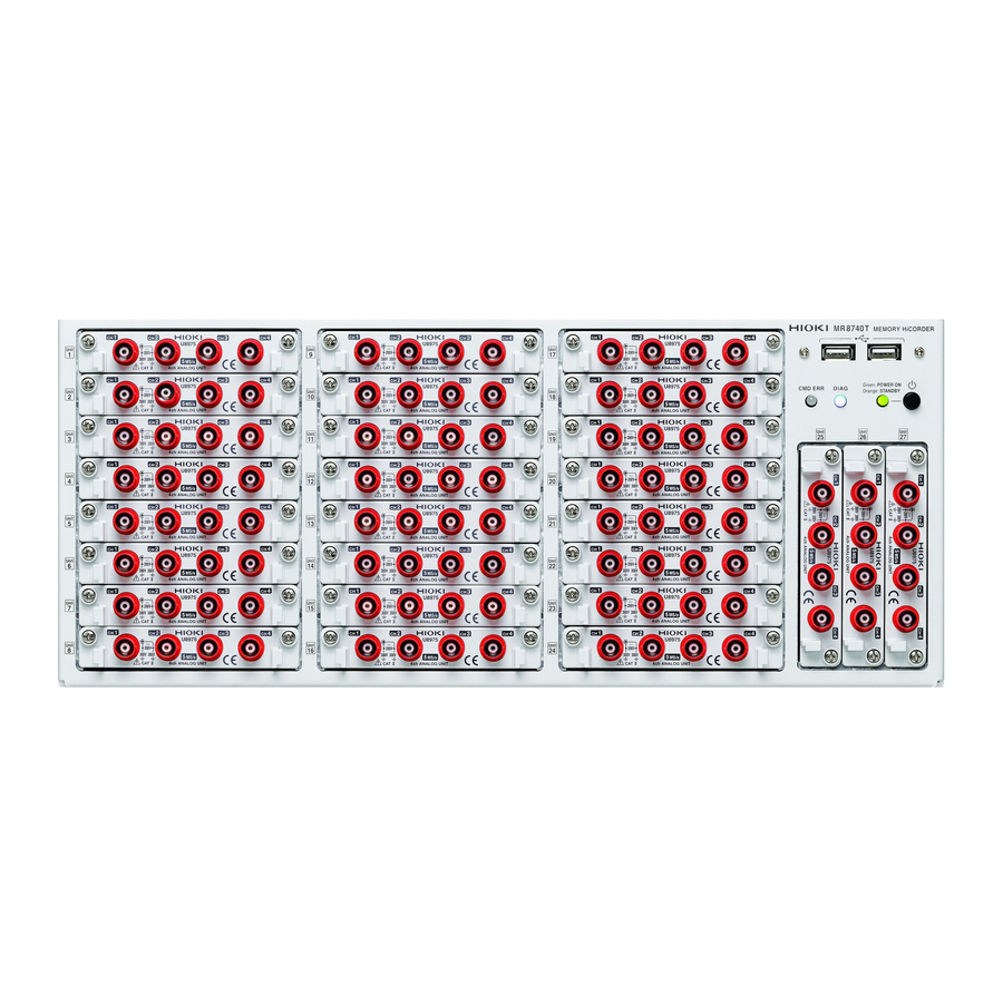
MR8740T
MR8740-50
MEMORY HiCORDER
Be sure to read this manual before using the instrument.
When using the instrument for the
first time
Name and Function of
Each Part
Measurement Method
Apr. 2021 Revised edition 4
MR8740C963-04 21-04H
p.22
p.67
HIOKI MR8740C963-04
Quick Start Manual
Troubleshooting
Maintenance and Service
Troubleshooting
Message
p.6
p.143
p.145
p.148
EN
Advertisement
Table of Contents

Subscribe to Our Youtube Channel
Related Manuals for Hioki MR8740T


Summary of Contents for Hioki MR8740T
- Page 1 MR8740T Quick Start Manual MR8740-50 MEMORY HiCORDER Be sure to read this manual before using the instrument. p.6 When using the instrument for the Troubleshooting first time Maintenance and Service p.143 Name and Function of p.22 Troubleshooting p.145...
- Page 2 HIOKI MR8740C963-04...
- Page 3 Refer to “3.6 Saving Data Consisting of Items Selected” (p. 76). To estimate file size Refer to “13.1 Information for Reference Purposes” of Instruction Manual. To open data files with a computer Refer to “4.3 Loading Data With Your Computer (Wave Viewer)” (p. 84). MR8740C963-04 HIOKI MR8740C963-04...
- Page 4 (p. 73) Configure the trigger settings. Starting/Stopping measurement (p. 75) Saving measured data files (p. 76) Analyzing waveforms (p. 81) Scroll through, zoom in, and zoom out waveforms. Read measured values (with the trace cursors). Finishing the measurement HIOKI MR8740C963-04...
-
Page 5: Table Of Contents
Strain gauge transducer ......41 4.3 Loading Data With Your Computer Current sensor ..........43 (Wave Viewer) ........84 ........47 Acceleration sensor ..49 Logic probe (Measuring logic signals) Specifications Connection cable ....49 (For precisely measuring voltage) Outputting waveforms .......50 5.1 Specifications of Model MR8740T ..87 Outputting pulse waveforms ......51 .......87 General specifications Outputting voltage, current, and ............92 Trigger ..........52 resistance ........94 Waveform screen ....53 Connection cable (high voltage) Setting screen ..........95... - Page 6 Memory check ........154 ..........155 LAN check ...........157 Media check System configuration check .....158 Cleaning the Instrument ....159 6.6 Disposing of the Instrument (Removing the lithium battery) ..159 Appendix Mounting the instrument in a rack ..161 Rack-mount brackets ......161 ...162 How to secure the rack-mount brackets Index Warranty Certificate HIOKI MR8740C963-04...
-
Page 7: Introduction
Introduction Introduction Thank you for choosing the Hioki MR8740T Memory HiCorder (Model MR8740-50). Preserve this manual carefully and keep it handy to make full use of this instrument for a long time. Following manuals are provided along with these models. Refer to manuals relevant to your purpose. - Page 8 Indicates DC (direct current). Indicates AC (alternating current). Symbols for Standards Indicates the Waste Electrical and Electronic Equipment Directive (WEEE Directive) in EU member states. Indicates that the product conforms to regulations set out by the EU Directive. HIOKI MR8740C963-04...
- Page 9 (maximum display value or scale length) f.s. The maximum displayable value or scale length. (displayed value) rdg. The value currently being measured and displayed on the measuring instrument. (setting value) setting Indicates the value set as the output voltage, current, or other quantity. HIOKI MR8740C963-04...
-
Page 10: Confirming Package Contents
Carefully check the accessories, panel keys and switches, and connectors. If the instrument seems to have been damaged or does not work as specified, contact your authorized Hioki distributor or reseller. Check that the package contents are correct. - Page 11 Options (sold separately) The options listed below are available for the instrument. To order an option, please contact your authorized Hioki distributor or reseller. Options are subject to change. Please check Hioki’s website for the latest information. For information about products, including cables, probes, and sensors, that can be connected to optional modules, see the “Options”...
-
Page 12: Safety Information
Protective gear WARNING Performing measurement using this instrument involves live-line work. To prevent an electric shock, use appropriate protective insulation and adhere to applicable laws and regulations. HIOKI MR8740C963-04... - Page 13 Service Entrance Internal Wiring Service Drop CAT II CAT IV CAT III Outlet Power Meter Fixed Installation The applicable measurement category is determined based on the module being used. Refer to “Handling the instrument and modules” (p. 10). HIOKI MR8740C963-04...
-
Page 14: Operation Precautions
• Check if there is any damage to the instrument occurred during storage or shipping and verify that it operates normally before using the instrument. If you find any damage, contact your authorized Hioki distributor or reseller. Installing the instrument and modules... - Page 15 • Do not stack the multiple instruments. • Vents must not be blocked. • To prevent overheating, be sure to leave 5 cm (2 inches) around the instrument. • The instrument should be operated only with the bottom side downwards. HIOKI MR8740C963-04...
- Page 16 60 V DC Model Digital Voltmeter Unit 500 V DC 300 V AC/DC (CAT II) MR8990 Model U8991 Digital Voltmeter Unit 100 V DC 100 V AC/DC High Maximum input voltage Model MR8740T Modules Maximum rated voltage to earth HIOKI MR8740C963-04...
- Page 17 Set attached 300 V AC/DC (CAT III) 600 V AC/DC (CAT II) Model P9000-01 Differential Probe – 1000 V AC/DC 1000 V AC/DC (CAT III) Model P9000-02 Differential Probe *: When Model U8974 High Voltage Unit is used HIOKI MR8740C963-04...
- Page 18 If you have lost any screws or find that any screws are damaged, please contact your authorized Hioki distributor or reseller. CAUTION • Do not touch module connectors inserted to the instrument to avoid damaging a module.
- Page 19 • Keep discs inside a protective case and do not expose to direct sunlight, high temperature, or high humidity. • Hioki is not liable for any issues your computer system experiences in the course of using this disc. HIOKI MR8740C963-04...
- Page 20 SSD unit of the instrument is limited by their flash memory. If data has been rewritten many times, data reading and writing capabilities will be degraded. In that case, replace the device. • Model Z4006 USB Drive can be used to save data. Use the product available as Hioki’s option only. (p. 5) HIOKI MR8740C963-04...
- Page 21 (power outrage or turning off a breaker). Since the battery has a limited life expectancy, it must regularly be replaced. When replacing batteries, please contact your authorized Hioki distributor or reseller. Expected lifetime: About 2 years (Operated at an ambient temperature of 25°, when the instrument is turned off once a day)
- Page 22 Using a non-specified cable may also result in incorrect measurements due to poor connection or other reasons. • To avoid electric shock, do not exceed the lower of the ratings shown on the modules and connection cords. HIOKI MR8740C963-04...
- Page 23 The following connection procedure is recommended to avoid this problem: • Connect the power cord provided Measuring to the instrument and supply Model MR8740T object power from the same outlet as the Logic Probe measuring object.
- Page 24 CAUTION Do not operate the instrument on any of the power sources (UPS or uninterruptible power supply, DC/AC inverter) that provide rectangular-wave or pseudo-sine-wave power. Doing so may damage the instrument. HIOKI MR8740C963-04...
- Page 25 Before connecting the instrument to external equipment DANGER To avoid electrical hazards and damage to the instrument, do not apply voltage exceeding the rated maximum to the external control terminals. Model MR8740T I/O terminal Maximum input voltage I/O terminals Maximum input voltage 10 V DC EXT.TRIG...
-
Page 26: How To Refer To This Document
Indicates the order of clicking the screens. The button represents the setting key. Procedure numbers Numbered same as a corresponding step-by-step instruction. Options and explanations Describes selectable settings when an item is clicked. The icon indicates the default setting of the item. HIOKI MR8740C963-04... -
Page 27: Overview 21
Multichannel simultaneous sampling This instrument can simultaneously measure signals across up to 108 channels. Extensive line of measurement modules Many types of measurement modules let the instrument measure a variety of signals that include voltage, current, temperature, and frequency. HIOKI MR8740C963-04... -
Page 28: Name And Function Of Each Part
Activates the instrument or puts it into standby when pressed. Indicates whether the instrument is powered on or in standby POWER lamp mode. p. 24 DIAG lamp Indicates instrument status. Command error lamp Lights up if a command error occurs. HIOKI MR8740C963-04... - Page 29 Do not Serial number remove this sticker as the number is important. – Inform your authorized Hioki distributor or reseller of this number if required. Main power switch Turns the instrument on and off.
- Page 30 Waiting for a trigger. Blue – The recording is in progress. Green – The recording is complete. Pink Switches to the normal operation indication when a new command is received. During normal operation (under White – suspension) HIOKI MR8740C963-04...
- Page 31 • Using a 4K-resolution monitor connected to the HDMI or DisplayPort terminal with the maximum resolution set may require longer time for processing command communication and displaying screens. *: Trademark of another company HIOKI MR8740C963-04...
-
Page 32: Screen
This screen is used to configure the system environment, communications, and external control terminal settings, and to initialize the instrument. You can also check the instrument configuration on this screen. Refer to “6.2 Initializing the Instrument” (p. 147). HIOKI MR8740C963-04... -
Page 33: Explanation Of Each Screen
Displays the number of measurement times. *1: Refer to “1.4 Specifying the Sheet Settings” of Instruction Manual. *2: Refer to “6 Search Function” of Instruction Manual. *3: Refer to “4 Saving/Loading Data and Managing Files” of Instruction Manual. HIOKI MR8740C963-04... - Page 34 Screen Cross-screen functions Name Description Menu tab Click a tab to choose a menu to open. Sub-menu tab Click a tab to choose a sub-menu to open. HIOKI MR8740C963-04...
-
Page 35: Basic Operation
External noise may cause the mouse to malfunction. Keep the mouse and mouse cable as far away as possible from sources of noise. Use the mouse on an insulated table. Some commercially available mouse devices are susceptible to noise and using such a mouse on a metal table may cause the instrument to malfunction. HIOKI MR8740C963-04... -
Page 36: Changing Screens And Settings
Changing screens and settings Switching between the waveform and setting screens Click the button to switch between the waveform and setting screens. Setting screen Waveform screen Switching the setting screens Click a tab to switch the setting screens. HIOKI MR8740C963-04... - Page 37 Basic Operation Choosing an option from a list Example: Choosing a sampling rate Example: Choosing a measurement range of Model 8966 Entering numerical values Example: Entering a user-defined recording length Example: Entering a scaling ratio HIOKI MR8740C963-04...
-
Page 38: Help Function (Displaying Instruction Manual)
Basic Operation Help Function (Displaying Instruction Manual) The HTML file of a selected manual appears. > [Func] > [Help] HIOKI MR8740C963-04... -
Page 39: Preparing For Measurement
Carefully read “Operation Precautions” (p. 8) before starting preparation. Keyboard, mouse Modules Connection cords (p. 29) (p. 34) (p. 36) External control Storage devices Computer terminals (p. 54) (p. 56, p. 84) (p. 58) Zero-adjustment Setting the clock Power cord (p. 64) (p. 61) (p. 63) HIOKI MR8740C963-04... -
Page 40: Installing And Removing Modules
Phillips-head screwdriver. Pinch the two knobs and pull out the module. When not installing any module after removal Install a blank panel. To order additional blank panels, contact your authorized Hioki distributor or reseller. Blank panel Place a blank panel. -
Page 41: Allocation Of Modules And Channels
Model 8973 Logic Unit can be installed in slots to which Unit 25, 26, or 27 is assigned only. You can find out information about the modules installed in the instrument in [System information]. Refer to “System configuration check” (p. 158). > [System] > [System information] HIOKI MR8740C963-04... -
Page 42: Attaching Connection Cords
(for measuring low-voltage) p. 38 Model L9217 Connection Cord Model L9790 Connection Cord Model L4940 Connection Cable High voltage Model U8974 High Voltage Unit p. 53 *: Model 9166 Connection Cord can be used for Model U8979 Charge Unit only. HIOKI MR8740C963-04... - Page 43 50 Model L9795-02 Connection Cable Commercially available cable Pulse Model MR8791 Pulse Generator Unit p. 51 (Half-pitch 50 pins) DC voltage DC current Commercially available cable Model U8794 VIR Generator Unit p. 52 Resistance (D-sub 25 pins) (simulated) HIOKI MR8740C963-04...
-
Page 44: Connection Cables (For Measuring Voltage, Frequency, Or Rotation Speed, And Obtaining Accumulations)
Example: Model P9000-02 Differential Probe *1: The maximum rated voltage to earth depends on a module to be used. *2: An optional power cord or AC adapter is required. *3: An optional AC adapter or a commercially available USB cable is required. HIOKI MR8740C963-04... - Page 45 Connect the connection cord clips to a measuring object. Lock Locking studs of module connector How to disconnect the cord Locking studs Turn the BNC male connector of the connection cable counterclockwise, and then pull out the connector. HIOKI MR8740C963-04...
-
Page 46: Thermocouple (Temperature)
EMC environment that includes external noise. • For K type and E type thermocouples, the physical phenomenon, short-range ordering can probably cause incorrect temperature measurement in the range of 250°C to 600°C. Contact a thermocouple manufacturer to choose proper thermocouples. HIOKI MR8740C963-04... -
Page 47: Strain Gauge Transducer
Connect a strain gauge transducer* to Model U8969 Strain Unit via Model L9769 Conversion Cable* *1: Hioki does not offer any strain gauge transducers. *2: Model L9769 Conversion Cable is an accessory of Model U8969 Strain Unit. CAUTION To prevent damage due to in a break in a conversion cable, do not excessively bend, pull, or twist the cables and joints between the cables and connectors. - Page 48 You can use your Model 8969 Strain Unit with the instrument. The instrument with Model 8969 Strain Unit installed refers to Model 8969 as [U8969] on the display. HIOKI MR8740C963-04...
-
Page 49: Current Sensor
Do not connect and remove a current sensor while the instrument remains on. Doing so will cause damage to the current sensor. Up to nine sensors can connect to Model 8971 Current Unit and Model U8977 3CH Current Unit all together. HIOKI MR8740C963-04... - Page 50 + 9318 1000 A CT9900 CT6876 AC/DC Current Sensor Metal DC to 1.5 MHz + 9318 1000 A Cannot CT6877 AC/DC Current Sensor Metal DC to 1 MHz connect *1: Metal connector (ME15W), plastic connector (PL23) HIOKI MR8740C963-04...
- Page 51 “-05,” which has a plastic connector (PL23), with Model U8977 3CH Current Unit. Model CT9900 Conversion Cable When Model CT9900 Conversion Cable is used, the instrument recognizes Model CT6846 or CT6865 (1000 A rating) as a 500-A AC/DC sensor. Set the conversion ratio to 2.00. HIOKI MR8740C963-04...
- Page 52 Using Model 9018-50 Clamp on Probe, you can measure a current using a voltage measurement module such as Model 8966 Analog Unit. Configuring the scaling settings allows measured waveforms to be displayed as current values. For the setup procedure, refer to “Converting Input Values (Scaling Function)” of the Instruction Manual. HIOKI MR8740C963-04...
-
Page 53: Acceleration Sensor
Acceleration sensor Connect a acceleration sensor* to Model U8979 Charge Unit Familiarize yourself with “Operation Precautions” (p. 8) before connecting a current sensor. *: Hioki does not offer any acceleration sensors. Acceleration sensor connectable with Model U8979 CAUTION Use an acceleration sensor with a built-in pre-amplifier that conforms to the specification of Model U8979 Charge Unit. - Page 54 Connecting an charge-output acceleration sensor equipped with a connector other than a miniature connector (#10-32) Convert the output connector into the miniature connector (#10-32) using a commercially available conversion connector or conversion cable to connect the sensor. HIOKI MR8740C963-04...
-
Page 55: Logic Probe (Measuring Logic Signals)
Connect the black lead to the L jack; and the red lead to the H jack. Make sure the test leads are fully inserted into the jacks. Connect the test leads to a measuring object. Black HIOKI MR8740C963-04... -
Page 56: Outputting Waveforms
Attach the connection cable. Output How to disconnect the cable from the output terminal terminal Hold the head of the SMB connector (other than the cable) and pull it out. SMB connector Attach the connection cable to a target. HIOKI MR8740C963-04... -
Page 57: Outputting Pulse Waveforms
Refer to “Model MR8791 Pulse Generator Unit” (p. 134). • The metal shell of the 10250-52A2PL connector is equipotential to the chassis ground (frame ground). • Use a lock-type connector to attach a harness to the connector of the module. HIOKI MR8740C963-04... -
Page 58: Outputting Voltage, Current, And Resistance
Attach the connection cable to a target. Output connector 09663527617, Harting (D-sub 25 pins, female) Refer to “Specifications of the output connector” (p. 136). The metal shell of the 09663527617 connector is equipotential to the chassis ground (frame ground). HIOKI MR8740C963-04... -
Page 59: Connection Cable (High Voltage)
Connect the plugs to the banana jacks of their respective colors. Insert the accessory clips into the clip ends of the connection cord. Connect the connection cord clips to a measuring object. Black HIOKI MR8740C963-04... -
Page 60: Connecting The External Control Terminals
The term “external control terminals” is used to refer to all of these terminals collectively. Refer to “Before connecting the instrument to external equipment” (p. 19). Model MR8740T External device Wires to be connected... - Page 61 [External terminal] screen, you can configure the following terminal: the external input (IN1, IN2), external output (OUT1, OUT2), and trigger output (TRIG.OUT). Use the [Trigger] screen to configure the external trigger (EXT.TRIG) setting. > [System] > [External terminal] HIOKI MR8740C963-04...
-
Page 62: Connecting The Instrument With Computers
Connecting one instrument to multiple PCs Connecting multiple instruments to one computer LAN cable* LAN cable* LAN cable* LAN cable* Model MR8740T Computer Computer Model MR8740T *: Use one of the following cables: • 1000BASE-T straight-through cable (maximum length: 100 m, commercially available) •... - Page 63 1000BASE-T connector of instrument accompanying crossover connector. Crossover connector Connect the crossover connector to the 1000BASE-T connector of the instrument. Model 9642 LAN Cable Connect Model 9642 LAN Cable to the 1000BASE-T connector of your computer. Connect it to your computer. HIOKI MR8740C963-04...
-
Page 64: Preparing Storage Devices (Recording Media)
Align the USB flash drive with the connector, and fully insert it. Rear side Front side Built-in drive The built-in drive is factory-formatted. Built-in SSD (capacity: 480 GB*) *: Once the SSD has been formatted, the actually available capacity decreases. You cannot remove the built-in drive. HIOKI MR8740C963-04... -
Page 65: Removing Storage Devices
Check whether the storage device is being accessed. removed. ® Be sure to use the remove button to remove any storage device. Do not use Windows Explorer or ® an icon on the Windows taskbar to remove the storage device. HIOKI MR8740C963-04... -
Page 66: Formatting Storage Devices
Note that formatting a storage device deletes all the information stored on the storage device and information deleted cannot be recovered. > [Func] > [Explorer] Click [Func]. Choose [Explorer]. Explorer appears. Right-click a storage device to be formatted. Click [Format] on the shortcut menu. HIOKI MR8740C963-04... -
Page 67: Supplying Power To The Instrument
Warm up the instrument for about 30 minutes. This warm-up stabilizes the temperature in the modules, yielding accurate measurement. Execute zero-adjustment. Refer to “2 Regulating the Zero Position (Zero- Adjustment)” (p. 64). Start a measurement. Refer to “3.5 Starting/Stopping Measurement” (p. 75). HIOKI MR8740C963-04... -
Page 68: Turning Off The Instrument
Confirm that the instrument is turned off before setting the main power switch to off. IMPORTANT ® Do not set the main power switch on the rear to off while Windows is running. Doing so may cause the instrument to start properly. HIOKI MR8740C963-04... -
Page 69: Setting The Clock
Doing so may cause unstable behavior of the system. The instrument regulates the clock internally. Always select > [System] > [Env.], and then click [Date and time] to set the clock. In any another way, the clock could not be set. HIOKI MR8740C963-04... -
Page 70: Regulating The Zero Position (Zero-Adjustment)
Zero-adjustment is invalid for Model U8969 Strain Unit. Regulate the zero position using the auto-balance. Refer to “Model U8969 Strain Unit” (p. 107). Refer to “Settings of the Model U8969 Strain Unit” in “3.6 Configuring Module-Specific Settings” of the Instruction Manual. HIOKI MR8740C963-04... - Page 71 The zero position may drift*. *: Drift: A phenomenon where a shift in the operating point of an operational amplifier causes a false output. Drift can result from a change in temperature and component aging over a period of use. HIOKI MR8740C963-04...
-
Page 72: Executing Calibration
The instrument starts to calibrate Model MR8990. Execute calibration again in the following cases: • After replacing any modules • After cycling the instrument • After initializing the instrument • When the ambient temperature has significantly changed The zero position may drift. HIOKI MR8740C963-04... -
Page 73: Measurement Method
Check if there is any damage to the instrument occurred during storage or shipping and verify that it operates normally before using the instrument. If you find any damage, contact your authorized Hioki distributor or reseller. Inspecting peripheral devices When using probes and connecting cords... -
Page 74: Setting Measurement Conditions
2.5 k , 5 k, 10 k, 20 k, 50 k, 100 k, 200 k, 500 k, 1 M, 2 M, 5 M, 10 M, 20 M, 50 M, 100 M HIOKI MR8740C963-04... -
Page 75: Sampling Rate Setting Guideline
To plot a sign wave that allows you to observe the peaks without any aliasing, the instrument needs to sample the waveform at a minimum of 25 points per cycle. To set the sampling rate automatically Refer to “3.7 Measuring Signals With the Auto-range Setting” (p. 78). HIOKI MR8740C963-04... -
Page 76: Configuring The Input Channel Settings
• When the input coupling method is set to GND, the instrument measures the ground potential in the module; thus, it does not measure any input waveforms. • An influence of the filter attenuation may prevent the instrument from setting an appropriate range. HIOKI MR8740C963-04... -
Page 77: Analog Channel
The measurement ranges that can be chosen varies depending on modules. If an input voltage exceeds the measurable range (overrange), change the measurement range to one with a lower sensitivity. HIOKI MR8740C963-04... - Page 78 You can also choose the same color as lines acquired across other channels. Switch the channels. Switch the channels by clicking the corresponding point on the display. HIOKI MR8740C963-04...
-
Page 79: Configuring The Level Trigger Settings
Enables the trigger function. Click the [Timing] box, and then choose a trigger recording method from the list. Start Starts recording when the instrument is triggered, and stops the recording after the instrument has acquired the recording-length waveforms. HIOKI MR8740C963-04... - Page 80 Only after the level-trigger condition is continuously satisfied during the specified period, an analog trigger is generated. This is useful to prevent the instrument from triggering due to noise. HIOKI MR8740C963-04...
-
Page 81: Starting/Stopping Measurement
To configuring measurement settings automatically Clicking [Auto range] on the waveform screen automatically specifies the sampling rate, measurement range, and zero position of the input waveform and start a measurement. Refer to “3.7 Measuring Signals With the Auto-range Setting” (p. 78). HIOKI MR8740C963-04... -
Page 82: Saving Data Consisting Of Items Selected
Number of characters for a file name: Up to 100 characters The maximum length of a file name that includes its path: Up to 255 characters Some characters or symbols are not accepted due to the file system restrictions. HIOKI MR8740C963-04... - Page 83 Saves all data written in the memory. and [B]. Saves the data in the section between trace cursors and [D]. Saves the data in the section between trace cursors Click [Execute]. HIOKI MR8740C963-04...
-
Page 84: Measuring Signals With The Auto-Range Setting
Detects trigger levels beginning from the channel lowest-numbered [Display] button set to [On]. among the channels with the Trigger type Level trigger (Slope: , Level: Automatically specified value, Filter: 10 samples) Measurement conditions Sampling rate Automatically set value Points 2.5 k Mode Repeat HIOKI MR8740C963-04... - Page 85 10 Hz. Manually choose a measurement range. • The auto-range function is not available for the following modules: Model 8967 Temp Unit Model U8969 Strain Unit Model 8970 Freq Unit Model MR8990 Digital Voltmeter Unit Model U8991 Digital Voltmeter Unit Model 8973 Logic Unit HIOKI MR8740C963-04...
- Page 86 Measuring Signals With the Auto-range Setting HIOKI MR8740C963-04...
-
Page 87: Analysis Method
Choose one or more cursors to be displayed from among [Trace cursor A] through [Trace cursor H] by tapping them. The chosen trace cursors are displayed on the waveform screen. Drag the trace cursors on the waveform screen to move them. HIOKI MR8740C963-04... - Page 88 [Trace cursor [Trace cursor B]) The instrument displays differences between cursors you choose in .←★確認★選択したカーソル間の差が に表示されます If you select a trace cursor other than the one selected in step , the instrument displays the strings [---] the difference field. HIOKI MR8740C963-04...
-
Page 89: Handling Waveforms
Wheel button Horizontal Point to a time axis value and rotate the wheel button. axis Vertical Rotate the wheel button while holding down the Shift key. axis Time axis Rotate the wheel button while holding down the Ctrl key. HIOKI MR8740C963-04... -
Page 90: Loading Data With Your Computer (Wave Viewer)
Click [Open]. The confirmation dialog box appears to check whether to continue the installation. Click [Next]. The window for selecting the installation folder opens. Click [Browse] to change the installation folder. Click [Next]. The installation starts. HIOKI MR8740C963-04... - Page 91 When you use Windows 10, click the Start button and select [Settings] > [Apps]. Select [HIOKI Wave Viewer (Wv)] to uninstall. Wave viewer is uninstalled. When updating Wave viewer to the latest version, uninstall the earlier version before installing the latest version.
- Page 92 Loading Data With Your Computer (Wave Viewer) HIOKI MR8740C963-04...
-
Page 93: Specifications
Specifications 5.1 Specifications of Model MR8740T General specifications 1. Basic specifications Recording method Normal (memory recording) Number of channels Analog: Up to 54 channels (when Model 8966 Analog Unit is used) With logic modules installed: Up to 48 channels for analog and up to 48 channels for... - Page 94 Approx. 426W × 177H × 505D mm (1cv 6.77″W × 6.97″H × 19.88″D) (excluding protrusions) Mass Approx. 14.0 kg (493.8 oz.) (Model MR8740T Memory HiCorder only) Approx. 20.8 kg (733.7 oz.) (with Model 8966 Analog Unit installed) Product warranty 3 years...
- Page 95 Specifications of Model MR8740T (2) USB interface Standards USB 3.0 compliant ×4, USB 2.0 compliant ×4 Number of ports Front side: 2 (USB 2.0) Rear side: 6 (USB 3.0 ×4, USB 2.0 ×2) Host Connector: Series-A receptacle Peripheral devices: keyboard, mouse, USB flash drive...
- Page 96 Specifications of Model MR8740T 5. External control terminals Terminal block Push-button type Maximum input 10 V DC External input voltage Input voltage High level: between 2.5 V and 10 V Low level: between 0 V and 0.8 V Acceptable pulse...
- Page 97 Specifications of Model MR8740T External sampling Maximum input 10 V DC input voltage Input voltage High level: between 2.5 V and 10 V, low level: between 0 V and 0.8 V Acceptable pulse High-level period: 50 ns or longer, low-level period: 50 ns or longer...
-
Page 98: Trigger
Specifications of Model MR8740T Trigger Trigger method Digital comparison method Trigger conditions Logical AND or OR operation among each trigger source and the interval trigger Trigger source Analog, logic • Up to 108 channels (Up to four analog triggers are available for one analog channel.) (Up to four logic triggers are available for one logic probe.) - Page 99 Specifications of Model MR8740T Trigger mark Trigger marks, which indicate the positions of trigger events, can be displayed. Trigger timing Start Alert function The alert function and trigger function other than the analog trigger setting are mutually exclusive. Available sampling rate: 100 kS/s or less...
-
Page 100: Waveform Screen
Specifications of Model MR8740T Waveform screen Display format Time-domain 1, 2, 4, 8, 16 screens waveform (Up to 64 channels can be displayed on each sheet.) representation: (Every channel can be set to be displayed on multiple sheets.) Sheet function Up to 16 sheets A display format can be chosen for each sheet. -
Page 101: Setting Screen
Specifications of Model MR8740T Setting screen Sampling rate Real-time sampling 20 M, 10 M, 5 M, 2 M, 1 M 500 k, 200 k, 100 k, 50 k, 20 k, 10 k, 5 k, 2 k, 1 k 500, 200, 100, 50, 20, 10, 5, 2, 1 [S/s] For the external sampling setting: Depends on a signal input to the external sampling terminal. - Page 102 Specifications of Model MR8740T Maximum recording Real-time sampling For the fixed recording length setting: length When 27 modules are used 2 M (with Model U8991 installed) 5 M (with Model U8975, U8977, U8978, or MR8990 installed) 10 M (54 channels, in points*)
-
Page 103: File
Specifications of Model MR8740T File 1. Data saving SSD: Built-in SSD (storage capacity: 480 GB) Destination to save USB flash drive: Model Z4006 USB Drive (16 GB) FTP transfer: Computer connected via LAN Email transmission: The instrument sends email messages with a file attached to user-defined destination. -
Page 104: Performing Calculation
Specifications of Model MR8740T 2. Data loading SSD: Built-in SSD (storage capacity: 480 GB) Drive from which USB flash drive: Model Z4006 USB Drive (16 GB) data is loaded Loadable data Setting data (.SET) formats Measured data: Binary format (.MEM) Index: Division save (.IDX) -
Page 105: Waveform Search
Specifications of Model MR8740T Waveform search Search method Trigger Level, window-in, window-out Logic trigger points can be searched for when the target channel is set to the logic channels. Peak Maximum, minimum, maximal, minimal Concierge Histogram or standard deviation (For each of them, a target for comparison can be chosen between the fundamental waveform and the previously observed waveform.) - Page 106 Specifications of Model MR8740T Auto Power on On/Off *On: Supplying the power can start the instrument. Time setting A date and time can be set. Number of current Up to nine sensors can connect to Model 8971 Current Unit and Model U8977 3CH sensors to be Current Unit in total.
-
Page 107: Specifications Of The Options
Consistent with the specifications of the Memory HiCorder in which Model 8966 is environment installed. Storage temperature −10°C to 50°C (14°F to 122°F), 80% RH or less (no condensation) and humidity Dimensions Approx. 106W × 19.8H × 196.5D mm (4.17″W × 0.78″H × 7.74″D) Mass Approx. 250 g (8.8 oz.) HIOKI MR8740C963-04... - Page 108 (With alligator clips attached: 600 V CAT III, 1000 V CAT II) Model P9000-01 Differential Probe (1000 V CAT III) Model P9000-02 Differential Probe (1000 V CAT III) Model 9665 10:1 Probe (300 V CAT II) Model 9666 100:1 Probe (300 V CAT II) HIOKI MR8740C963-04...
-
Page 109: Model 8967 Temp Unit
Approx. 106W × 19.8H × 204.5D mm (4.17″W × 0.78″H × 8.05″D) Mass Approx. 240 g (8.5 oz.) Effect of radiated ±2% f.s. (max.) at 3 V/m radio-frequency electromagnetic field Effect of conducted ±2% f.s. (max.) at 3 V radio-frequency electromagnetic field HIOKI MR8740C963-04... - Page 110 2000°C f.s. 400°C to 1800°C 0.1°C 200°C f.s. 0°C to 200°C 0.01°C (WRe5- 1000°C f.s. 0°C to 1000°C 0.05°C 2000°C f.s. 0°C to 2000°C 0.1°C *1: Not including reference junction compensation accuracy *2: JIS C 1602-1995 *3: ASTM E-988-96 HIOKI MR8740C963-04...
-
Page 111: Model 8968 High Resolution Unit
Consistent with the specifications of the Memory HiCorder in which Model 8968 is environment installed. Storage temperature −10°C to 50°C (14°F to 122°F), 80% RH or less (no condensation) and humidity Dimensions Approx. 106W × 19.8H × 196.5D mm (4.17″W × 0.78″H × 7.74″D) Mass Approx. 250 g (8.8 oz.) HIOKI MR8740C963-04... - Page 112 (With alligator clips attached: 600 V CAT III, 1000 V CAT II) Model P9000-01 Differential Probe (1000 V CAT III) Model P9000-02 Differential Probe (1000 V CAT III) Model 9665 10:1 Probe (300 V CAT II) Model 9666 100:1 Probe (300 V CAT II) HIOKI MR8740C963-04...
-
Page 113: Model U8969 Strain Unit
(between each input channel and enclosure, between any two of input channels) Anticipated transient overvoltage: 330 V Measurement ±0.5% f.s. ±4 µε (with the filter set at 5 Hz) accuracy Temperature Gain: ±0.05% f.s./°C characteristics Zero-position: ±2.5 µε/°C HIOKI MR8740C963-04... - Page 114 ±10% f.s. (max.) at 3 V/m (with the filter set at 5 Hz) radio-frequency electromagnetic field Effect of conducted ±10% f.s. (max.) at 3 V (with the filter set at 5 Hz) radio-frequency electromagnetic field Low-pass filter Off, 5 ±30%, 10 ±30%, 100 ±30%, 1 k ±30% (Hz); −3 dB HIOKI MR8740C963-04...
-
Page 115: Model 8970 Freq Unit
0.01 Hz (power frequency mode) Response time Within the sum of 40 µs and the sampling interval of the instrument in which the module is installed Input voltage range ±10 V, ±20 V, ±50 V, ±100 V, ±200 V, ±400 V HIOKI MR8740C963-04... - Page 116 (With alligator clips attached: 600 V CAT III, 1000 V CAT II) Model P9000-01 Differential Probe (1000 V CAT III) Model P9000-02 Differential Probe (1000 V CAT III) Model 9665 10:1 Probe (300 V CAT II) Model 9666 100:1 Probe (300 V CAT II) HIOKI MR8740C963-04...
-
Page 117: Model 8971 Current Unit
(Each sensor requires both Model 9318 Conversion Cable and Model CT9901 Conversion Cable to connect with Model 8971 Current Unit) • Hioki current sensors with RM515EPA-10PC (Hirose) installed (Supported conversion ratio: 2 V/20 A, 2 V/50 A, 2 V/200 A, 2 V/500 A, 2 V/1000 A* Measurement range •... - Page 118 Approx. 250 g (8.8 oz.) Standards Safety: EN61010 EMC: EN61326 Class A Accessories Model 9318 Conversion Cable ×2 (for connecting current sensors) Options Model 9318 Conversion Cable Model CT9901 Conversion Cable Number of installable Up to four modules modules HIOKI MR8740C963-04...
-
Page 119: Model 8972 Dc/Rms Unit
Consistent with the specifications of the Memory HiCorder in which Model 8972 is installed temperature and humidity Operating Consistent with the specifications of the Memory HiCorder in which Model 8972 is installed environment Storage temperature −10°C to 50°C (14°F to 122°F), 80% RH or less (no condensation) and humidity HIOKI MR8740C963-04... - Page 120 (With alligator clips attached: 600 V CAT III, 1000 V CAT II) Model P9000-01 Differential Probe (1000 V CAT III) Model P9000-02 Differential Probe (1000 V CAT III) Model 9665 10:1 Probe (300 V CAT II) Model 9666 100:1 Probe (300 V CAT II) HIOKI MR8740C963-04...
-
Page 121: Model 8973 Logic Unit
−20°C to 50°C (−4°F to 122°F), 80% RH or less (no condensation) and humidity Dimensions Approx. 106W × 19.8H × 196.5D mm (4.17″W × 0.78″H × 7.74″D) Mass Approx. 190 g (6.7 oz.) Standards Safety: EN61010 EMC: EN61326 Class A HIOKI MR8740C963-04... -
Page 122: Model Mr8990 Digital Voltmeter Unit
Ω Common-mode 100 dB or more (at 50 Hz / 60 Hz, a signal source resistance of 100 or less) rejection ratio Input type Unbalanced input (floating) Input terminals Banana jacks Maximum input 500 V DC voltage HIOKI MR8740C963-04... - Page 123 Effect of radiated ±0.1% f.s. (max.) at 3 V/m (with the 100 mV f.s. range) radio-frequency electromagnetic field Standards Safety: EN61010 EMC: EN61326 Class A Option Model L2200 Test Lead (600 V CAT IV, 1000 V CAT III, 10 A) HIOKI MR8740C963-04...
-
Page 124: Model U8974 High Voltage Unit
(between each input channel and the enclosure, between any two of input channels) Anticipated transient overvoltage: 8000 V Operating Consistent with the specifications of Memory HiCorder in which Model U8974 is installed. temperature and humidity Operating Consistent with the specifications of Memory HiCorder in which Model U8974 is installed. environment HIOKI MR8740C963-04... - Page 125 (attached to the tips of Model L4940, 600 V CAT IV, 1000 V CAT III, 10 A) Model L4934* Small Alligator Clip Set (300 V CAT III, 600 V CAT II, 3 A) *: Model L4932 is required when Model L4934 is used. HIOKI MR8740C963-04...
-
Page 126: Model U8975 4Ch Analog Unit
16 bits (± f.s. = ±32000 data points) Maximum sampling 5 MS/s rate Guaranteed accuracy 1 year period Guaranteed 1 year accuracy period after adjustment made by Hioki Measurement ±0.1% f.s. (with the filter set at 5 Hz) accuracy HIOKI MR8740C963-04... - Page 127 (With alligator clips attached: 600 V CAT III, 1000 V CAT II) Model P9000-01 Differential Probe (1000 V CAT III) Model P9000-02 Differential Probe (1000 V CAT III) Model 9665 10:1 Probe (300 V CAT II) Model 9666 100:1 Probe (300 V CAT II) HIOKI MR8740C963-04...
-
Page 128: Model U8977 3Ch Current Unit
Approx. 106W × 19.8H × 196.5D mm (4.17″W × 0.78″H × 7.74″D) Mass Approx. 250 g (8.8 oz.) Product warranty 3 years period Options Model CT9900 Conversion Cable (PL23 receptacle–ME15W plug) Model CT9920 Conversion Cable (PL14 receptacle–ME15W plug) Number of input 3 channels channels HIOKI MR8740C963-04... - Page 129 10 mA p-p (max.) (using the 20 A sensor, with the 2 A f.s. range, with input terminals connected with each other) Low-pass filter Off, 5 Hz, 500 Hz, 5 kHz, 200 kHz ±50%; −3 dB Input type Current sensor Measurement LR10-DC12BR (Hirose connector) terminal Input coupling DC/GND HIOKI MR8740C963-04...
- Page 130 Effect of conducted ±5% f.s. (max.) at 3 V (using the 20 A sensor, with the 20 A f.s. range, with the filter set at radio-frequency 5 Hz, with a current of 2 A DC inputted) electromagnetic field HIOKI MR8740C963-04...
-
Page 131: Model U8978 4Ch Analog Unit
Input capacitance 30 pF ±10 pF (at 100 kHz) A/D resolution 16 bits (± f.s. = ±32000 data points) Maximum sampling 5 MS/s rate Guaranteed accuracy 1 year period Guaranteed 1 year accuracy period after adjustment made by Hioki HIOKI MR8740C963-04... - Page 132 (With alligator clips attached: 600 V CAT III, 1000 V CAT II) Model P9000-01 Differential Probe (1000 V CAT III) Model P9000-02 Differential Probe (1000 V CAT III) Model 9665 10:1 Probe (300 V CAT II) Model 9666 100:1 Probe (300 V CAT II) HIOKI MR8740C963-04...
-
Page 133: Model U8979 Charge Unit
(between each input channel and the enclosure, between any two of input channels) Anticipated transient overvoltage: 330 V -2. Voltage input Measurement range 10, 20, 40, 100, 200, 400 mV f.s., 1, 2, 4, 10, 20, 40 V f.s. Maximum input 40 V DC voltage HIOKI MR8740C963-04... - Page 134 ) to 5.0 mV/(m/s 1, 2, 4, 10, 20, 40, 100, 200, 400, 1 k, 2 k, 4 k m/s f.s. Measurement sensitivity: 5.001 mV/(m/s ) to 10.0 mV/(m/s Frequency 1 Hz to 50 kHz, −3 dB characteristics HIOKI MR8740C963-04...
- Page 135 -5. Specifications for accuracy Conditions of Guaranteed accuracy period: 1 year guaranteed accuracy Guaranteed accuracy period after adjustment made by Hioki: 1 year Temperature and humidity for guaranteed accuracy: 23°C ±5°C (73°F ±9°F), 80% RH or less Warm-up time: 30 minutes or more...
-
Page 136: Model U8991 Digital Voltmeter Unit
High-speed The high-speed response can be switched between on and off. response Guaranteed accuracy 1 year period Guaranteed 1 year accuracy period after adjustment made by Hioki Measurement ±0.02% rdg. ±0.0025% f.s. accuracy Temperature (±0.002% rdg.±0.00025% f.s.)/°C characteristics HIOKI MR8740C963-04... - Page 137 Model L9217 Connection Cord (300 V CAT III, 600 V CAT II, 0.2 A) Model L9790 Connection Cord (With Model L9790-01 or Model 9790-03 attached: 300 V CAT III, 600 V CAT II, 1 A) (With Model 9790-02 attached: 150 V CAT III, 300 V CAT II, 1 A) HIOKI MR8740C963-04...
-
Page 138: Model Mr8790 Waveform Generator Unit
Safety: EN61010 EMC: EN61326 Class A Effect of radiated ±3% f.s. (max.) at 3 V/m (f.s. = 10 V) radio-frequency electromagnetic field Effect of conducted ±1% f.s. (max.) at 3 V (f.s. = 10 V) radio-frequency electromagnetic field HIOKI MR8740C963-04... - Page 139 Setting range: −10 V to 10 V (The peak value, which is the total of amplitude and DC offset, is limited to ±10 V) Setting resolution: 1 mV, offset accuracy: ±3 mV DC output Output accuracy: ±0.6 mV HIOKI MR8740C963-04...
-
Page 140: Model Mr8791 Pulse Generator Unit
High level: 3.4 V or more, low level: 1.6 V or less Relay switching time 5 ms or less (switching between logic and open-collector, between output and open [self- diagnosis]) Standards Safety: EN 61010 EMC: EN 61326 Class A HIOKI MR8740C963-04... - Page 141 Range: 0 Hz to 120 kHz (common for 8 channels) Setting resolution: 10 Hz Frequency accuracy: Consistent with the time-axis accuracy of Memory HiCorder in which Model MR8791 is installed. Memory (pattern) 2,048 words (16,384 bits = 2,048 words × 8 bits/word) HIOKI MR8740C963-04...
- Page 142 F_GND: CH1 through Pulse output CH8: I_GND: Isolated ground F_GND: Non-isolated ground (frame ground) Not connected TESTn: Do not connect a test pin. Recommended connection cable: Model KB-SHH2K Sanwa Supply brand (SCSI-2 connector, Centronics half-pitch, 50 pins, male) HIOKI MR8740C963-04...
-
Page 143: Model U8794 Vir Generator Unit
DC voltage Amplitude 5.0 V p-p Setting resolution: 0.1 V DC offset 0.0 V to 2.5 V Setting resolution: 0.1 V Frequency 10 Hz, 20 Hz, 50 Hz, 100 Hz Measurement item DC voltage, DC current, AC current HIOKI MR8740C963-04... - Page 144 Anticipated transient overvoltage: 25 V Conditions of Guaranteed accuracy period: 1 year guaranteed accuracy Guaranteed accuracy period after adjustment made by Hioki: 1 year Temperature and humidity for guaranteed accuracy: 23°C ±5°C (73°F ±9°F), 80% RH or less Warm-up time: 30 minutes or more *When outputting a resistance •...
- Page 145 (A setting resistance and an output resistance of a connected object are in a ratio 1:1, with no capacitive load) When connected-object presumption is not performed: 1.5 s or less (response coefficient of resistance generation: 0.0002) When connected-object presumption is performed: 100 ms or less HIOKI MR8740C963-04...
- Page 146 1% f.s. (Max.) at 3 V/m (for DC voltage output function) radio-frequency electromagnetic field Effect of conducted 1% f.s. (Max.) at 3 V (for DC voltage output function) radio-frequency electromagnetic field No accuracy is specified for AC voltage output and AC current measurement. HIOKI MR8740C963-04...
- Page 147 10 ms, the inter-capacitance is determined to be 0 pF. Calculation 1.6 seconds (max.) time Offset cancel Measures an output-circuit offset with the measurement circuit and outputs Operation a signal with the offset subtracted. Default setting HIOKI MR8740C963-04...
- Page 148 Connector used: 25 pins, female, locking-block screws #4-40 Connector pin-out Signal name Signal name CH8_GND CH8_RESERVE CH8_OUTPUT CH7_GND CH7_RESERVE CH7_OUTPUT CH6_GND CH6_RESERVE CH6_OUTPUT CH5_GND CH5_RESERVE CH5_OUTPUT CH4_GND CH4_RESERVE CH4_OUTPUT CH3_GND CH3_RESERVE CH3_OUTPUT CH2_GND CH2_RESERVE CH2_OUTPUT CH1_GND CH1_RESERVE CH1_OUTPUT HIOKI MR8740C963-04...
-
Page 149: Maintenance And Service
The calibration period varies depending on the state of the instrument and installation environment. We recommend that the calibration period be determined in accordance with the state of the instrument and installation environment. Please contact your authorized Hioki distributor or reseller to have your instrument periodically calibrated. - Page 150 The characteristics of some of the parts used in the instrument may deteriorate with extended use. To ensure the instrument can be used over the long term, it is recommended to replace these parts on a periodic basis. When replacing batteries, please contact your authorized Hioki distributor or reseller.
-
Page 151: Troubleshooting
Troubleshooting 6.1 Troubleshooting If damage is suspected, read the “Before having the instrument repaired” section before contacting your authorized Hioki distributor or reseller. Before sending the instrument for repair If the start button does not work correctly Reference Problem Check item or cause... - Page 152 60 required before first use. *: “4.4 Managing Files” of Instruction Manual If the cause cannot be revealed Initialize the instrument. All settings are restored to the factory default. Refer to “6.2 Initializing the Instrument” (p. 147). HIOKI MR8740C963-04...
-
Page 153: Initializing The Instrument
Initialize all Restores all the settings to the factory default. However, the following settings are not restored: • Clock setting > [System] > [Date and time]) > [Comm.] > [Open PC settings]) • Computer setting Click [OK]. HIOKI MR8740C963-04... -
Page 154: Message
Some of the warning and information messages disappear in a few seconds. Check the details while the screen is displaying the message. To inform of a message with a beep Select [System] > [Env.], and set [Beep sound] [Alert] or [Alert+Action]. Refer to “10 Specifying the System Environment Settings” of Instruction Manual. HIOKI MR8740C963-04... -
Page 155: Error Messages
Error messages The list of error messages is as follows. Check the solution. If an error is displayed on the screen at power-on, the instrument is necessary to be repaired. Contact your authorized Hioki distributor or reseller. Message Solution Reference page... -
Page 156: Warning Messages
“Analog channels” in 1.3 of No channel selected for use. more of the channels to [On]. Instruction Manual Check the search criteria “6 Search Function” of Invalid search condition. setting. Instruction Manual Aborted. – – HIOKI MR8740C963-04... - Page 157 POP3 may not be to Computers” of Instruction Server. running on the specified server. Manual Check the recipient’s and “11 Connecting the Instrument E-mail ‘to’ or ‘from’ settings sender’s addresses of the email to Computers” of Instruction invalid. setting. Manual HIOKI MR8740C963-04...
- Page 158 File processing error. drive is being processed. (Recording Media)” (p. 58) Replace the storage device with another or cycle the instrument. “2.8 Regulating the Zero Zero-adjustment required. Execute zero-adjustment. Position (Zero-Adjustment)” (p. 64) Current sensor recognized. – – HIOKI MR8740C963-04...
- Page 159 Check the scope of search. search. Instruction Manual Unable to capture a stable Check the setting for the “6 Search Function” of fundamental wave. fundamental wave. Instruction Manual Cannot set numerical value. Check the setting of upper and – – lower limits. HIOKI MR8740C963-04...
-
Page 160: Self-Check
• Save measured data in a storage device before performing the memory check. Any measured data will be deleted after the memory check. • Do not turn off the instrument during the memory check. Click [Memory check]. Click [Execute]. The memory check starts. The memory check will finish in about 30 seconds. HIOKI MR8740C963-04... -
Page 161: Lan Check
This check tests the LAN cable for a break or other malfunctions. Click [Memory check]. Enter an IP address used for connecting to LAN in the [Address] box. Click [Open]. Check the results of transmission and reception on the screen. HIOKI MR8740C963-04... - Page 162 [Yes] is displayed in the [Enabled] column of [File and Printer Sharing (Echo Request - ICMPv4-In)]. [No] is displayed in the [Enabled] column, an error will occur during the LAN check. Right-click the row and select [Enable Rule]. HIOKI MR8740C963-04...
-
Page 163: Media Check
This check tests the storage devices for malfunction. Click [Memory check]. Click the [Media] box and choose a storage device from the list. The screen displays the information of the chosen storage device. Click [Read/Write check]. The read/write check starts. HIOKI MR8740C963-04... -
Page 164: System Configuration Check
You can check the system configuration, software version numbers, and configuration board versions of the instrument. Module You can check the model number, name, resolution, sampling rate, and configuration firmware version number of each module (unit) installed in the instrument. HIOKI MR8740C963-04... -
Page 165: Cleaning The Instrument
If the date and time deviate substantially at power-on, it is the time to replace that battery. Contact your authorized Hioki distributor or reseller. • The battery is subject to self-discharge. Be sure to charge the battery before initial use. If the OS does not correctly shut down even after the battery is recharged, it is the time to replace that battery. - Page 166 Pull the lithium battery up from the circuit board, and cut the positive and negative leads with the nippers. Put the lithium battery up out of the CPU board, and cut the leads with the nippers. Lithium battery Lead Board HIOKI MR8740C963-04...
-
Page 167: Appendix
The instrument can be installed in a rack using rack-mount brackets. Rack-mount brackets EIA standard Material: EN AW-5052 (EN), 5052 (ASTM) Thickness: 3 37.7 101.6 37.7 6xC2 2x 7.1 37.7 50.8 50.8 37.7 2xC5 6x 4.5 2xC2 (Unit: mm) HIOKI MR8740C963-04... -
Page 168: How To Secure The Rack-Mount Brackets
• Leave 20 mm or more from the bottom side and the sides that have the vents (upper, right, left, and bottom sides). • If you need the screws (M4 × 8 mm), please contact your authorized Hioki distributor or reseller. -
Page 169: Index
Thermocouple............40 Trace cursor ............. 81 Trigger ..............73 IN1 ................19 TRIG.OUT ..............19 IN2 ................19 Type (Saving type)............ 77 Initializing the instrument ........147 USB flash drive ............58 LAN................56 Level trigger .............. 73 HIOKI MR8740C963-04... - Page 170 Index Warm-up ..............61 Warning ..............150 Waveform viewer ............84 Zero-adjustment ............64 Zoom in..............83 Zoom out ..............83 HIOKI MR8740C963-04...
- Page 171 HIOKI MR8740C963-04...
- Page 172 HIOKI MR8740C963-04...
- Page 173 HIOKI MR8740C963-04...
- Page 174 HIOKI MR8740C963-04...
Need help?
Do you have a question about the MR8740T and is the answer not in the manual?
Questions and answers