
Subscribe to Our Youtube Channel
Related Manuals for ADDAC System ADDAC307 Heart Sensing


Summary of Contents for ADDAC System ADDAC307 Heart Sensing
- Page 2 1x 2x3 pin male pinheaders 2x B10k metal shaft potentiometers 1x B10k trimmer potentiometer 1x B10k trimmer potentiometer with Mid-Stop 3x Mono Jacks 1x Stereo Jack 2x Leds 1x 2x5 boxed power header 1x Ribbon connector ADDAC SYSTEM page 2...
- Page 3 Cut and SAVE the excess legs. STEP 2: Locate the small pcb board and solder the excess legs in the 3 holes higlighted below. After that solder it to the bottom board like shown below. ADDAC SYSTEM page 3...
- Page 4 Next pick up the top pcb. Locate and solder the 2x3 female connector like shown below. STEP 5: Locate the screws and spacers and place them like shown below, please note the plastic screw goes on the bottom hole. ADDAC SYSTEM page 4...
- Page 5 Pick the black wire, cut it into 3 pieces, strip it and pre tin the stripped tips. Solder it to the 3 holes like shown below. STEP 7: Grab the the 2 trim pots and flatten out their legs with the help of some pliers, like shown below. ADDAC SYSTEM page 5...
- Page 6 Place all front panel parts in the pcb. Do Not solder anything just yet! STEP 10: Place the front panel and tighten the 3 nuts Make sure the pcb is parallel to the frontpanel Keep lines parallel ADDAC SYSTEM page 6...
- Page 7 Top view after all front panel parts are soldered. STEP 12: Next we’ll connect both pcbs, follow the soldering of the 3 wires like shown below. Also place the 2x3 male header into the female header. ADDAC SYSTEM page 7...
- Page 8 ADDAC307 Assembly Guide STEP 13: Last step, close the 2 pcbs together, place the bottom 2 screws and solder the 2x3 male header. ADDAC SYSTEM page 8...
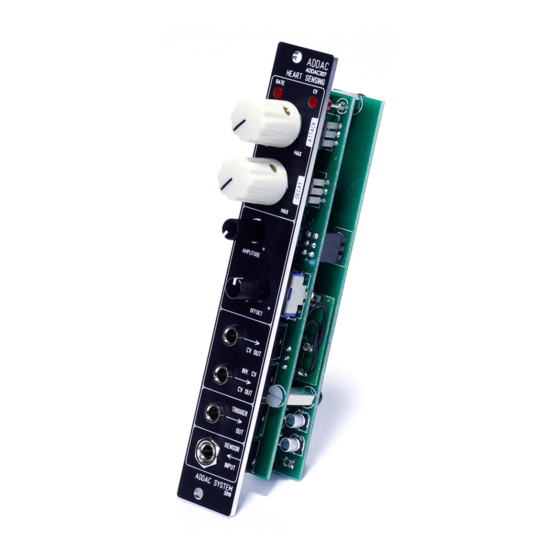
- Page 9 ADDAC307 Assembly Guide Finish it by placing the knobs and you’re all done! Happy patching! ADDAC SYSTEM page 9...
-
Page 10: Assembly Guide
For feedback, comments or problems please contact us at: addac@addacsystem.com ADDAC307 ASSEMBLY GUIDE Revision.01 May.2019...
Need help?
Do you have a question about the ADDAC307 Heart Sensing and is the answer not in the manual?
Questions and answers