Subscribe to Our Youtube Channel
Summary of Contents for ADDAC System ADDAC217
- Page 2 ADDAC217 Assembly Guide July.2020 ADDAC SYSTEM page 2...
- Page 3 ADDAC217 Assembly Guide STEP 1: Start by locating the 2 capacitors, notice the orientation printed on the pcb. Tip: soldering these caps is easy, just place a dab of solder on the pad on your right (left pad if you’re left handed) and then, with the help of a tweezer, put the capacitor in place and reflow the previously tinned pad to melt the solder while pushing the capacitor down.
- Page 4 ADDAC217 Assembly Guide STEP 2: Next carefully break the 2 pcbs apart and proceed to locate the male and female pinheaders and solder them like shown below. STEP 3: Next locate and solder the IDC Connector, notice the orientation printed on the pcb..
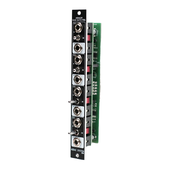
- Page 5 ADDAC217 Assembly Guide STEP 4: Next place all parts of the pcb and follow up by placing the frontpanel and tighten the nuts. After everything is in place proceed by soldering all pads. ADDAC SYSTEM page 5...
- Page 6 ADDAC217 Assembly Guide STEP 5: Finish by attaching both boards together. ADDAC SYSTEM page 6...
- Page 7 ADDAC217 Assembly Guide Congratulations you’re done! Happy Patching! ADDAC SYSTEM page 7...
- Page 8 For feedback, comments or problems please contact us at: addac@addacsystem.com ADDAC217 ASSEMBLY GUIDE Revision.01 July.2020...


Need help?
Do you have a question about the ADDAC217 and is the answer not in the manual?
Questions and answers